Page 989 of 1701

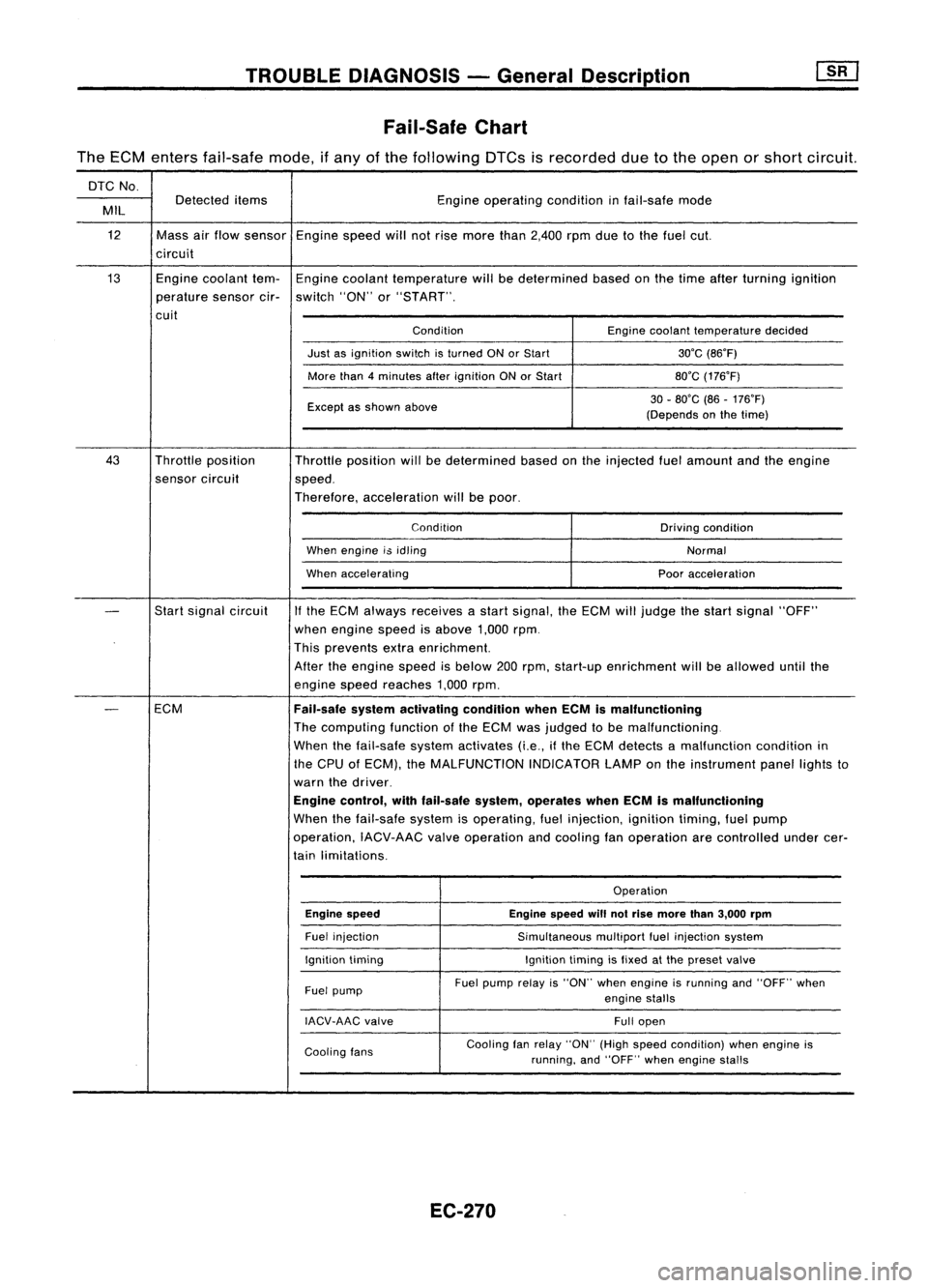
TROUBLEDIAGNOSIS -General Description
Fail-Safe Chart
The ECM enters fail-safe mode,ifany ofthe following DTCsisrecorded duetothe open orshort circuit.
DTC No.
Detected items Engineoperating conditioninfail-safe mode
MIL
12 Massairflow sensor Enginespeedwillnotrise more than2,400 rpmduetothe fuel cut.
circuit
13 Enginecoolant tem-Engine coolant temperature willbedetermined basedonthe time after turning ignition
perature sensorcir-switch "ON"or"START".
cuit ConditionEnginecoolant temperature decided
Just asignition switchisturned ONorStart 30'C(86'F)
More than4minutes afterignition ONorStart 80'C(176'F)
Except asshown above 30
-80'C (86-176'F)
(Depends onthe time)
43 Throttle position
Throttleposition willbedetermined basedonthe injected fuelamount andtheengine
sensor circuit
speed.
Therefore, acceleration willbepoor.
Condition Drivingcondition
When engine i$idling
Normal
When accelerating Pooracceleration
-
Start
signal circuit
If
the ECM always receives astart signal, theECM willjudge thestart signal "OFF"
when engine speedisabove 1,000rpm.
This prevents extraenrichment.
After theengine speedisbelow 200rpm, start-up enrichment willbeallowed untilthe
engine speedreaches 1,000rpm.
-
ECM
Fail-safesystemactivating conditionwhenECMismalfunctioning
The computing functionofthe ECM wasjudged tobe malfunctioning.
When thefail-safe systemactivates (i.e.,ifthe ECM detects amalfunction conditionin
the CPU ofECM), theMALFUNCTION INDICATORLAMPonthe instrument panellightsto
warn thedriver.
Engine control, withfail-safe system,operates whenECMismalfunctioning
When thefail-safe systemisoperating, fuelinjection, ignitiontiming,fuelpump
operation, IACV-AACvalveoperation andcooling fanoperation arecontrolled undercer-
tain limitations.
Operation
Engine speed Enginespeedwillnotrise more than3,000 rpm
Fuel injection
Simultaneousmultiportfuelinjection system
Ignition timing Ignitiontimingisfixed atthe preset valve
Fuel pump Fuel
pump relayis"ON" whenengine isrunning and"OFF" when
engine stalls
IACV-AAC valve
Fullopen
Cooling fans Cooling
fanrelay "ON" (Highspeed condition) whenengine is
running, and"OFF" whenengine stalls
EC-270
Page 1001 of 1701
![NISSAN ALMERA N15 1995 Service Manual TROUBLEDIAGNOSIS -General Description
[![]
ECM Terminals andReference Value(Cont'd)
ECM inspection table
*Dataarereference
values.
TERMINAL WIRE
ITEM
NO. COLOR CONDITION
'DATA
[Engine isr NISSAN ALMERA N15 1995 Service Manual TROUBLEDIAGNOSIS -General Description
[![]
ECM Terminals andReference Value(Cont'd)
ECM inspection table
*Dataarereference
values.
TERMINAL WIRE
ITEM
NO. COLOR CONDITION
'DATA
[Engine isr](/manual-img/5/57349/w960_57349-1000.png)
TROUBLEDIAGNOSIS -General Description
[![]
ECM Terminals andReference Value(Cont'd)
ECM inspection table
*Dataarereference
values.
TERMINAL WIRE
ITEM
NO. COLOR CONDITION
'DATA
[Engine isrunninQ]
0.2-0.3V
L Idle speed
1
W/B
Ignitionsignal
IEngineisrunning.1
L Engine speedis2,000 rpm. Approximately
0.7V
2 LlOR Tachometer IEngine
isrunning]
Approximately0.9V
L Idle speed
3 GY/R
Ignitioncheck !Engine
isrunning.1
Approximately13V
L Idle speed
IEngine isrunning.1
I
Ilgnition switch"OFF"I
0-1V
ECCS relay(Self-shut- L
For afew seconds afterturning ignition
4
WIG
switch"OFF"
off)
Ilgnitionswitch"OFF"I
BATTERYVOLTAGE
L Afew seconds afterturning ignition switch
(11-14V)
"OFF" andthereafter
6
B/W
ECCSground IEngine
isrunning.1
Engineground
L Idle speed
7
G/B
Approximately13.5V
14
G/W
Datalinkconnector forIEngine
isrunning.1
ApproximatelyOV
15 GY/L CONSULT
LIdle speed Approximately
2.5V
23
G/R
ApproximatelyOV
IEngine isrunning.1
BATTERYVOLTAGE
Cooling fanrelay (Low L
Cooling fanisnot operating. (11
-14V)
9 LG/R
speed) IEngineisrunning.1
L Cooling fanisoperating. Approximately
OV
IEngine isrunning.1
BATTERYVOLTAGE
Cooling fanrelay
t
Cooling fanisnot operating.
(11-14V)
10 LG Cooling
fanisoperating atlow speed.
(High speed)
IEngineisrunning.1
L Cooling fanisoperating athigh speed. Approximately
OV
IEngine isrunning.1
L Both
A/C
switch andblower fanswitch areApproximately
OV
11 Y Airconditioner relay "ON".
IEngine isrunning.1
BATTERYVOLTAGE
LAIC switchis"OFF". (11
-14V)
13
B/W
ECCSground IEngine
isrunning.1
Engineground
L Idle speed
EC-282
Page 1004 of 1701
![NISSAN ALMERA N15 1995 Service Manual TROUBLEDIAGNOSIS -General Description
[]K]
ECM Terminals andReference Value(Cont'd)
'Data arereference values.
TERMINAL WIRE
ITEM CONDITION
'DATA
NO. COLOR
Ilgnitionswitch"ON"I
NISSAN ALMERA N15 1995 Service Manual TROUBLEDIAGNOSIS -General Description
[]K]
ECM Terminals andReference Value(Cont'd)
'Data arereference values.
TERMINAL WIRE
ITEM CONDITION
'DATA
NO. COLOR
Ilgnitionswitch"ON"I](/manual-img/5/57349/w960_57349-1003.png)
TROUBLEDIAGNOSIS -General Description
[]K]
ECM Terminals andReference Value(Cont'd)
'Data arereference values.
TERMINAL WIRE
ITEM CONDITION
'DATA
NO. COLOR
Ilgnitionswitch"ON"I
L
For 5seconds afterturning ignition switch
"ON" Approximately
OV
104 B/P Fuelpump relay !Engine
isrunning.1
Ilgnition switch"ON"I
BATTERY VOLTAGE
L
5seconds afterturning ignitionswitch
(11-14V)
"ON" andthereafter
IEngine isrunning.1
0.6-0.8V
EGR valve
&
EVAP
.L
Engine speedis4,000 rpm.
105 P canisterpurgecontrol
solenoid valve IEngine
isrunning.1
BATTERYVOLTAGE
L
Idle speed (11
-14V)
107 IEngine
isrunning.j
B/Y ECCSground
L
Engine
ground
108 Idlespeed
!Engine isrunning.1
Approximately0.2V
L
Engine speedisbelow 3,200rpm.
Heated oxygen sensor
111 OR
heater IEngineisrunning.1
BATTERY VOLTAGE
L
Engine speedisabove 3,200rpm. (11
-14V)
IEngine isrunning.\
11-14V
L
Idle speed
113 SB IACV-AAC
valve lEngine
isrunning.1
~ Sle«;ng wheel;,be;ng I"med
2-11V
Air conditioner isoperating.
Rear window defogger switchis"ON".
Lighting switchis"ON".
!Engine isrunning.1
ApproximatelyOV
Torque converter
L
Idle speed
115 P/B clutch
solenoid valve
IEngineisrunning.1 (Warm-up condition)
(A/T
models)
L
Vehicle speedis60 km/h (37MPH) or BA
TTERY VOLTAGE
(11 -14V)
more in"D" position
116 BIY ECCS
ground IEngine
isrunning.1
Engineground
L
Idle speed
EC-285
•
Page 1005 of 1701
TROUBLEDIAGNOSIS FORPOWER SUPPLV
Main Power Supply andGround Circuit
EC-MAIN-01
GNO GNO GNDGND GNDGNDGND
-C -C -E-E -E-I -I
13.91 I~SI 11~71
1I1~1 11~61~~
B B B/YB/Y B/YB/W B/W
LI II II I
, I--i
'-e-e-=e----l
B B BB/Y
.~ L, -:
+
* -:
CF13)
ill
Refer
toEL-POWER.
ECM
(ECCS
CONTROL
MODULE)
em
Detectable line
for DTC
Non-detectable line forDTC
Refer
toEL-POWER.
ST IGNITION
SWITCH
~
30A
OJ
~
B/R
I
B/R
d:::.(llii)
I~I(]ID
B/R
ICDI@
=r@
B/R
I
B/R
~
IGN
SW
7.5A
[ill
W!L
d:::.
(E10n
I~I (MS)
W!L
*@
~@
W!L
I
e----'--,
W/LW/L
IT
]1
ECCS
~ RELAY
Ibi=Jl Ibi=Jl
@
WIG W/R
I
+--~
WIG W/R W/R
m
';sl \171
SSOFF VBVB
'--I
W/L W/L
14'61
h1~1
BATT CRTN
~II
Illij
@
3456 W
Acrn
T
L
~
(E114)
[mJID
W
Refer
tolast page
(Foldout page).
em
L
HEC002
EC-286
Page 1007 of 1701
![NISSAN ALMERA N15 1995 Service Manual TROUBLEDIAGNOSIS FORPOWER SUPPLY
[gJ
Main Power Supply andGround Circuit(Cont'd)
@
~IV ~i5
Ie
ECM E!'CONNECTORI! +351
38.47
~
SEF460Q
ts
3 2
1
5
I!]
CHECK HARNESS CONTINUITY
BETWEE NISSAN ALMERA N15 1995 Service Manual TROUBLEDIAGNOSIS FORPOWER SUPPLY
[gJ
Main Power Supply andGround Circuit(Cont'd)
@
~IV ~i5
Ie
ECM E!'CONNECTORI! +351
38.47
~
SEF460Q
ts
3 2
1
5
I!]
CHECK HARNESS CONTINUITY
BETWEE](/manual-img/5/57349/w960_57349-1006.png)
TROUBLEDIAGNOSIS FORPOWER SUPPLY
[gJ
Main Power Supply andGround Circuit(Cont'd)
@
~IV ~i5
Ie
ECM E!'CONNECTORI! +351
38.47
~
SEF460Q
ts
3 2
1
5
I!]
CHECK HARNESS CONTINUITY
BETWEEN ECCSRELAY ANDECM
1. Disconnect ECMharness connector.
2. Disconnect ECCSrelayharness con-
nector.
3. Check harness continuity between
ECM terminals
@,@
and terminal
@.
Continuity shouldexist.
If OK, check harness forshort.
OK
CHECK VOLTAGE BETWEEN ECCS
RELAY ANDGROUND.
Check voltage between terminals
(!),
@
and ground withCONSULT or
tester.
Voltage: Batteryvoltage NG
NG
Repair
harness orcon-
nectors.
Check thefollowing.
• Harness connectors
@,@
• Harness connectors
@,
• Harness foropen or
short between ECCS
relay andbattery
If NG, repair harness or
connectors.
Repair harness orcon-
nectors.
Replace ECCSrelay.
NG
NG
OK
OK
[!1
CHECK ECCSRELAY.
1. Apply 12Vdirect current between
relay terminals
(!)
and
@.
2. Check continuity betweenrelayter-
minals
@
and
@.
12V
«(!) .
@) applied:
Continuity exists.
No voltage applied:
No continuity
Ii
CHECK OUTPUT SIGNALCIRCUIT.
Check harness continuity betweenECM
terminal
@
and terminal
@.
Continuity shouldexist.
If OK, check harness forshort.
AEC684
AEC492
~i5
•
JO[CONNECTOR
II
4
ECM
Ii
OK
III
CHECK GROUND CIRCUIT.
1. Turn ignition switch"OFF".
2. Loosen andretighten engineground
screws.
3. Disconnect ECMharness connector.
4. Check harness continulty between
ECM terminals
@,
@,@,
@,
@,
COO,GID
andengine ground.
Continuity shouldexist. .
If OK, check harness forshort.
NG
Repair harness orcon-
nectors.
SEF090M OK
III
~15@a
II
ECM ~CONNECTOR
II
6'13'39048'107'108'116
.
.
LEn
Check
ECMpinterminals fordamage
and check theconnection ofECM har-
ness connector.
INSPECTION END
SEF461Q EC-288
Page 1009 of 1701
TROUBLEDIAGNOSIS FORDTC11 [][]
Camshaft PositionSensor(CMPS) (Cont'd)
EC-CMPS-01
Refer' toEL-POWER. _.
Detectable line
for' DTC
-: Non-detectab Ie
line for'DTC
t
...
B B B
1..1 J
m m
ECM
(ECCS
CONTROL
MODULE)
em
DISTRIBUTOR
(CAMSHAFT
POSITION
SENSOR)
ern>
"'
J.
...
---
u,,;J~1!.i=ll
L B!W B
JOINTCONNECTOR-6
@
l'" --- ....
~==~-- •
"
B!W
B!W
Ii3'n1
1:0
I
POS POS
rT
L L
12~1 13.01
REF REF
W!L
I
W!L
Ifii'ii\
r=b\!JQ!,
I~I (MB)
W!L
,rID'@
=r='@
W!L
I
T-,
W!L W!L
I!~I
ECCS
~ RELAY
!bi=UI!.i=U
CEID
WIG W!R
I
.
--_.
I
"
WIG
W!R W!R
rhU3'sn~
SSOFF VBVB
(Ill
I
I~
@
~5
1
CF
L3)
3456 W
T
~
rn>
~@
(11213415\6)
GY
ITIIIIIIIillI
GY
Refer
tolast page
(Foldout page).
em
L
HEC003
EC-290
Page 1010 of 1701

•
NG
Check thefollowing.
• Harness foropen or
short between camshaft
position sensorand
ECCS relay
If NG, repair harness or
connectors.
NG Repair harness orcon-
nector.
INSPECTION
START
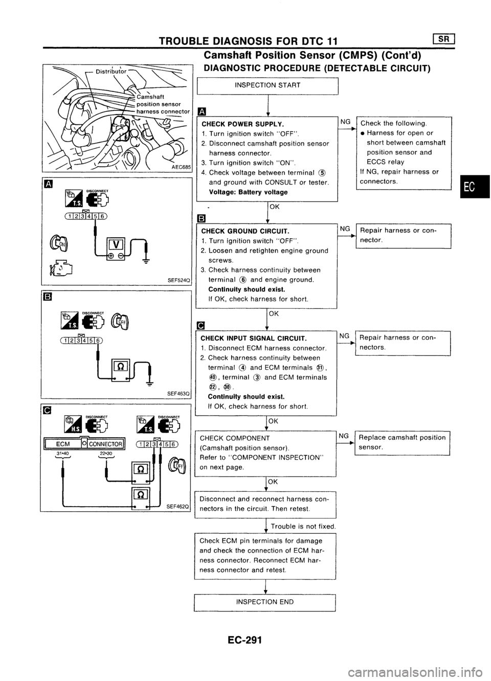
CHECK POWER SUPPLY.
1. Turn ignition switch"OFF".
2. Disconnect camshaftpositionsensor
harness connector.
3. Turn ignition switch"ON".
4. Check voltage between terminal
@
and ground withCONSULT ortester.
Voltage: Batteryvoltage
CHECK GROUND CIRCUIT.
1.
Turn ignition switch"OFF".
2. Loosen andretighten engineground
screws.
3. Check harness continuity between
SEF524Q
terminal
@
and engine ground.
Continuity shouldexist.
If OK, check harness forshort.
TROUBLE
DIAGNOSIS FOROTC11 [][]
Camshaft PositionSensor(CMPS) (Cont'd)
DIAGNOSTIC PROCEDURE(DETECTABLE CIRCUIT)
~i5
@a
( 1121\'ij151~
SEF463Q
[!J
~15 ~15
II
ECM
ECONNECTORII
mmJili)
31.40
f
~Q~ ~
'-.,-J
.---
[fiJ
..
-
SEF462Q CHECK
INPUTSIGNAL CIRCUIT.
1. Disconnect ECMharness connector.
2. Check harness continuity between
terminal
@
and ECM terminals
@,
@l,
terminal
@
and ECM terminals
@,@.
Continuity shouldexist.
If OK, check harness forshort.
OK
CHECK COMPONENT
(Camshaft positionsensor).
Refer to"COMPONENT INSPECTION"
on next page.
OK
Disconnect andreconnect harnesscon-
nectors inthe circuit. Thenretest. NG
Repair harness orcon-
nectors.
NG Replace camshaft position
sensor.
Trouble isnot fixed.
Check ECMpinterminals fordamage
and check theconnection ofECM har-
ness connector. ReconnectECMhar-
ness connector andretest.
INSPECTION END
EC-291
Page 1013 of 1701
TROUBLEDIAGNOSIS FORDTC12 [][]
Mass AirFlow Sensor (MAFS) (Coni'd)
EC-MAFS-01
Refer toEL-POWER.
-:Oetectable line
for DTG
-: Non-detectable
line forDTC
11
B B B
t...J
1
(ffi)
ECM
(EGCS
CONTROL
MODULE)
em
OR
W
w=IT5il~
QA+ QA-
"
... 1
JOINT
CONNEGTOR-6
@
( ....-m=_
~=P:1
W!R
W
3 MASS
AIR
FLOW
SENSOR
lbjdJlbj:Jlm OR W
t
W!L
I
W!L
iETtITI
1Fst11~
~@
W/L
,ctJ,@
=r(ffi
W!L
I
T-,
W!L W!L
I!~I
EGGS
~ RELAY
1ki=JI1'=i=!'@
WIG W!R
I
.--_
....
I
"
WIG
W!RW!R
wtilli1Bnd7n
SSOFF VBVB
~II
I'fil
em
3456 W
~
cn.g:oo
BR
~@
CDODDDJDJJJD
GY
Refer
tolast page
(Foldout page).
em
L
HEC004
EC-294