Page 328 of 1701
TROUBLEDIAGNOSES
CONSULT
CONSULT APPLICATION TOASS
ITEM SELF-DIAGNOSTIC
DATAMONITOR ACTIVETEST
RESULTS
Front rightwheel sensor
XX
-
Front leftwheel sensor
XX
-
Rear rightwheel sensor
XX
-
Rear leftwheel sensor
XX
-
Stop lamp switch
-
X
-
Front rightinletsolenoid valve
XXX
Front rightoutlet solenoid valve
X
XX
Front leftinlet solenoid valve
XXX
Front leftoutlet solenoid valve
XX
X
Rear rightinletsolenoid valve
XX
X
Rear leftinlet solenoid valve
XXX
Rear rightoutlet solenoid valve
X
XX
Rear leftoutlet solenoid valve
X
X
.X
Actuator solenoid valverelay
XX
-
Actuator motorrelay
(ABS MOTOR isshown onthe Data Monitor
X
XX
screen.)
ABS warning lamp
-
X
-
Battery voltage
XX
-
X: Applicable
-; Not applicable
ECU partnumber mode
Ignore theECU partnumber displayed inthe ECU PART NUMBER MODE.Refertoparts catalog toorder
the ECU.
BR-58
Page 330 of 1701
TROUBLEDIAGNOSES
CONSULT Inspection Procedure(Conl'd)
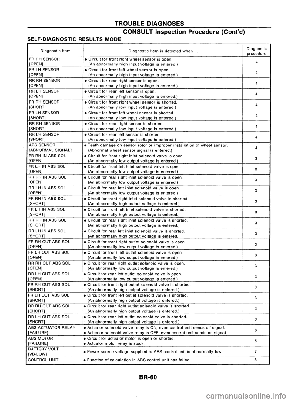
SELF-DIAGNOSTIC RESULTSMODE
Diagnostic item
Diagnosticitemisdetected when... Diagnostic
procedure
FR RH SENSOR
•Circuit forfront rightwheel sensor isopen.
4
[OPEN] (Anabnormally highinput voltage isentered.)
FR LH SENSOR
•Circuit forfront leftwheel sensor isopen.
4
[OPEN] (Anabnormally highinput voltage isentered.)
RR RHSENSOR
•Circuit forrear right sensor isopen.
4
[OPEN] (Anabnormally highinput voltage isentered.)
RR LHSENSOR
•Circuit forrear leftsensor isopen.
4
[OPEN] (Anabnormally highinput voltage isentered.)
FR RH SENSOR
•Circuit forfront rightwheel sensor isshorted.
4
[SHORT] (Anabnormally lowinput voltage isentered.)
FR LH SENSOR
•Circuit forfront leftwheel sensor isshorted.
4
[SHORT] (Anabnormally lowinput voltage isentered.)
RR RH SENSOR
•Circuit forrear right sensor isshorted.
4
[SHORT] (Anabnormally lowinput voltage isentered.)
RR LHSENSOR
•Circuit forrear leftsensor isshorted.
4
[SHORT] (Anabnormally lowinput voltage isentered.)
ABS SENSOR
•Teeth damage onsensor rotororimproper installation ofwheel sensor.
4
[ABNORMAL SIGNAL]
(Abnormalwheelsensor signalisentered.)
FR RH INABS SOL
•Circuit forfront rightinletsolenoid valveisopen.
3
[OPEN] (Anabnormally lowoutput voltage isentered.)
FR LH INABS SOL
•Circuit forfront leftinlet solenoid valveisopen.
3
[OPEN] (Anabnormally lowoutput voltage isentered.)
RR RH INABS SOL
•Circuit forrear right inletsolenoid valveisopen.
3
[OPEN] (Anabnormally lowoutput voltage isentered.)
RR LHINABS SOL
•Circuit forrear leftinlet solenoid valveisopen.
3
[OPEN] (Anabnormally lowoutput voltage isentered.)
FR RH INABS SOL
•Circuit forfront rightinletsolenoid valveisshorted.
3
[SHORT] (Anabnormally highoutput voltage isentered.)
FR LH INABS SOL
•Circuit forfront leftinlet solenoid valveisshorted.
3
[SHORT] (Anabnormally highoutput voltage isentered.)
RR RH INABS SOL
•Circuit forrear right inletsolenoid valveisshorted.
3
[SHORT] (Anabnormally highoutput voltage isentered.)
RR LHINASS SOL
•Circuit forrear leftinlet solenoid valveisshorted.
3
[SHORT] (Anabnormally highoutput voltage isentered.)
FR RH OUT ABSSOL
•Circuit forfront rightoutlet solenoid valveisopen.
3
[OPEN] (Anabnormally lowoutput voltage isentered.)
FR LH OUT ASS SOL
•Circuit forfront leftoutlet solenoid valveisopen.
3
[OPEN] (Anabnormally lowoutput voltage isentered.)
RR RH OUT ASSSOL
•Circuit forrear right outlet solenoid valveisopen.
3
[OPEN] (Anabnormally lowoutput voltage isentered.)
RR LHOUT ABSSOL
•Circuit forrear leftoutlet solenoid valveis.open.
3
[OPEN] (Anabnormally lowoutput voltage isentered.)
FR RH OUT ASSSOL
•Circuit forfront rightoutlet solenoid valveisshorted.
3
[SHORT] (Anabnormally highoutput voltage isentered.)
FR LH OUT ABSSOL •Circuit forfront leftoutlet solenoid valveisshorted.
3
[SHORT] (Anabnormally highoutput voltage isentered.)
RR RHOUT ABSSOL •Circuit forrear right outlet solenoid valveisshorted.
3
[SHORT] (Anabnormally highoutput voltage isentered.)
RR LHOUT ASSSOL •Circuit forrear leftoutlet solenoid valveisshorted.
3
[SHORT] (Anabnormally highoutput voltage isentered.)
ABS ACTUATOR RELAY
•Actuator solenoid valverelayisON, even control unitsends offsignal.
6
[FAILURE] •Actuator solenoid valverelayisOFF, even control unitsends onsignal.
ABS MOTOR
•Circuit foractuator motorisopen orshorted.
5
[FAILURE] •Actuator motorrelayisstuck.
BATTERY VOLT
•Power source voltage supplied toABS control unitisabnormally low. 7
[VB-LOW]
CONTROL UNIT •Function ofcalculation inASS control unithasfailed.
8
BR-50
Page 333 of 1701
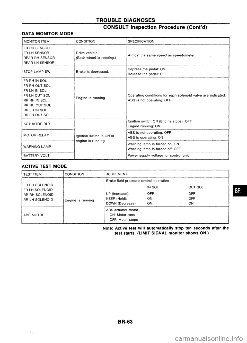
DATAMONITOR MODE TROUBLE
DIAGNOSES
CONSULT Inspection Procedure(Cont'd)
MONITOR ITEM CONDITION
SPECIFICATION
FR RH SENSOR
FR LHSENSOR Drive
vehicle.
Almostthesame speed asspeedometer.
REAR RHSENSOR (Each
wheel isrotating.)
REAR LHSENSOR
STOP LAMP SW Brake
isdepressed. Depress
thepedal: ON
Release thepedal: OFF
FR RH INSOL
FR RH OUT SOL
FR LH INSOL
FR LH OUT SOL
Engineisrunning. Operating
conditions foreach solenoid valveareindicated.
RR RH INSOL ABS
isnot operating: OFF
RR RH OUT SOL
.
RR LHINSOL
RR LHOUT SOL
IgnitionswitchON(Engine stops):OFF
ACTUATOR RLY
Enginerunning: ON
MOTOR RELAY ABS
isnot operating: OFF
Ignition switchisON or
ABSisoperating: ON
engine isrunning.
WARNING LAMP Warning
lampisturned on:ON
Warning lampisturned off:OFF
BATTERY VOLT Power
supply voltage forcontrol unit
ACTIVE TESTMODE
TEST ITEM CONDITION JUDGEMENT
Brake fluidpressure controloperation
FR RH SOLENOID
INSOL OUTSOL
FR LH SOLENOID
RR RH SOLENOID UP
(Increase): OFF OFF
RR LHSOLENOID
Engineisrunning. KEEP
(Hold): ON OFF
DOWN (Decrease): ON ON
ABS actuator motor
ABS MOTOR ON:
Motor runs
OFF: Motor stops
Note: Active testwillautomatically stoptenseconds afterthe
test starts. (LIMIT SIGNAL monitorshowsON.)
BR-63
•
Page 334 of 1701
TROUBLEDIAGNOSES
Component PartsandHarness Connector
Location
RHO models
Dualproportioning
valve
DABS warninglamp
X
1.1
ABS relay box
Brake master cylinder ~
Rear wheel sensors
Ii
Rear rightwheel
sensor connector
[i1
Rear leftwheel
sensor connector
• For LHD models, controlunit
is located onthe opposite side.
SBR047DA
BR-64
Page 336 of 1701
TROUBLEDIAGNOSES
Ground CircuitCheck
ACTUATOR MOTORGROUND
• Check resistance betweenactuatormotorground terminal
and body ground.
Resistance:
on
SBR055D
[( C/UNIT CONNECTOR
28 .29 .39
p~
15
CONTROL
UNITGROUND
• Check resistance betweentheterminals andground.
Resistance:
on
SBR237D
~ABS relaybox6-pin connector (bodyside)
EtiD
r:tt
°i5
T
[ill
SBR931CBABS
RELAY BOXGROUND
• Check resistance betweenASSrelay boxharness 6-pincon-
nector (bodyside)terminal @and ground.
Resistance:
on
BR-66
Page 338 of 1701
TROUBLEDIAGNOSES
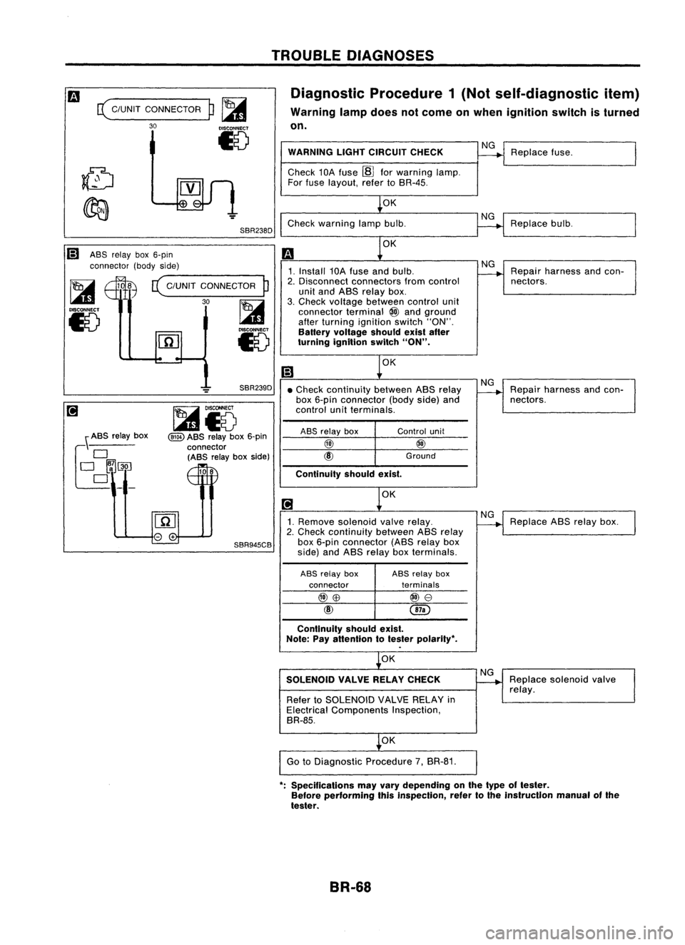
Diagnostic Procedure1(Not self-diagnostic item)
Warning lampdoes notcome onwhen ignition switchisturned
on.
c(
C/UNIT CONNECTOR
30
p~
15
SBR238D WARNING
LIGHTCIRCUIT CHECK
Check 10Afuse ~forwarning lamp.
For fuse layout, refertoSR-4S.
OK
Check warning lampbulb.
NG
NG
Replace
fuse.
Replace bulb.
Ii) ASSrelay box6-pin
connector (bodyside)
~ 108
c(
C/UNIT CONNECTOR
P
I...a1
30~
15
l.41
Iv
OK
1. Install 10Afuse andbulb.
2. Disconnect connectors fromcontrol
unit and ASS relay box.
3. Check voltage between controlunit
connector terminal
@
and ground
after turning ignition switch"ON".
Battery voltage shouldexistafter
turning ignition switch
"ON".
OK
NG
Repair harness andcon-
nectors.
OK
Continuity
shouldexist.
•
Check continuity betweenASSrelay
box 6-pin connector (bodyside)and
control unitterminals.
\ ASS relay box
f~~~_
SBR239D
~i5
@ID
ASS relay box6-pin
connector (ASS relayboxside)
108
ASS
relay box
@)
Control
unit
@
Ground
NG
Repair harness andcon-
nectors.
1. Remove solenoid valverelay.
2. Check continuity betweenASSrelay
SBR945CB
box6-pin connector (ASSrelaybox
side) andASS relay boxterminals.
ASS relay box ASS
relay box
connector terminals
@)\B
@e
@
Continuity shouldexist.
Note: Payattention totester polarity",
OK
SOLENOID VALVERELAYCHECK
Refer toSOLENOID VALVERELAY in
Electrical Components Inspection,
BR-8S.
OK
Go toDiagnostic Procedure7,BR-81.
NG
NG
Replace
ABSrelay box.
Replace solenoid valve
relay.
": Specifications mayvary depending onthe type oftester.
Before performing thisinspection, refertothe instrucllon manualofthe
tester.
BR-68
Page 339 of 1701
TROUBLEDIAGNOSES
SBR969CB
ABS
relay box
~
o
DO
!MJ
•
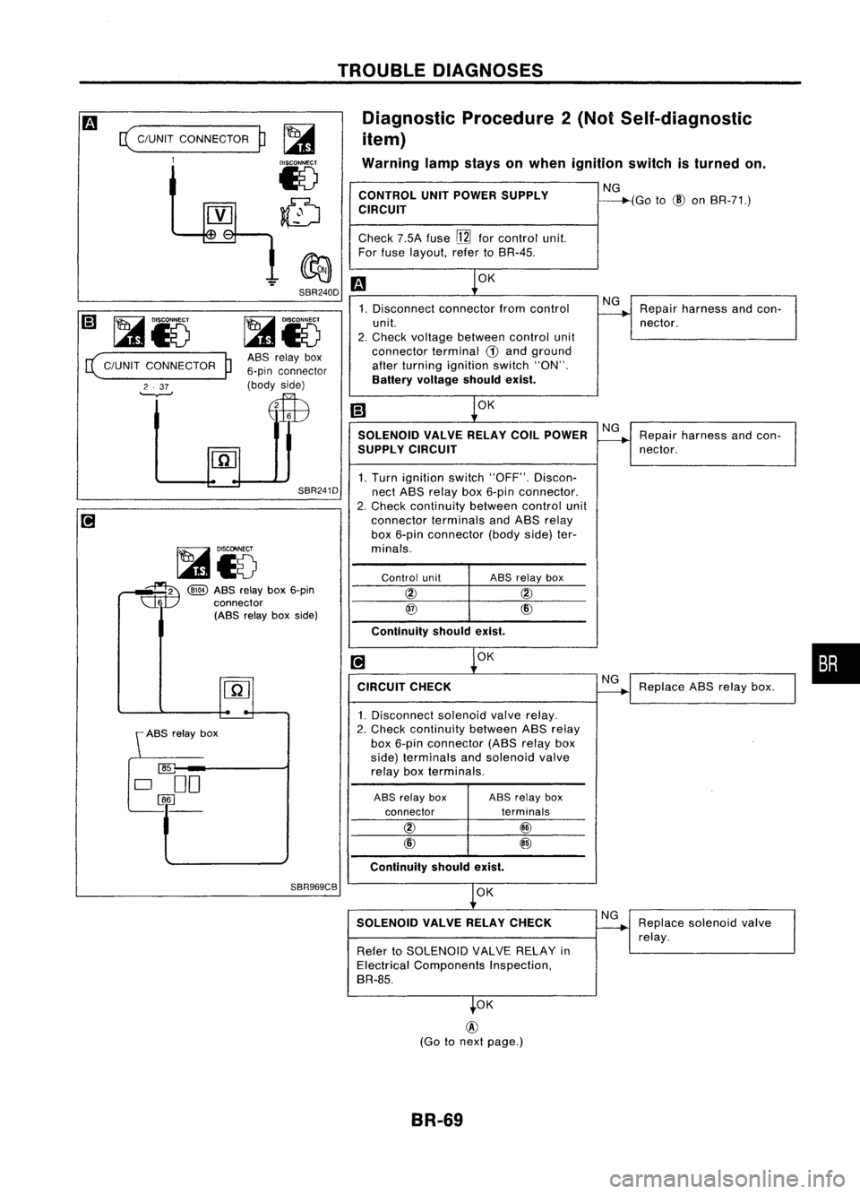
Diagnostic
Procedure2(Not Self-diagnostic
item)
Warning lampstays onwhen ignition switchisturned on.
CONTROL UNITPOWER SUPPLY NG
CIRCUIT ----"""'(Go
to
(!)
onBR-71.)
Check 7.5Afuse
[ll]
forcontrol unit.
For fuse layout, refertoBR-45.
m
OK
1. Disconnect connectorfromcontrol NG
Repair harness andcon-
unit.
----.......
nector.
2. Check voltage between controlunit
connector terminal
(i)
and ground
alter turning ignition switch"ON".
Battery voltage shouldexist.
[;]
~OK
SOLENOID VALVERELAYCOILPOWER NG
Repair harness andcon-
SUPPL YCIRCUIT
----+
nector.
1. Turn ignition switch"OFF". Discon-
nect ABS relay box6-pin connector.
2. Check continuity betweencontrolunit
connector terminalsandABS relay
box 6-pin connector (bodyside)ter-
minals.
Control unit ABS
relay box
@ @
@
CID
Continuity shouldexist.
[!]
~OK
CIRCUIT CHECK
~Replace
ABSrelay box.
1. Disconnect solenoidvalverelay.
2. Check continuity betweenABSrelay
box 6-pin connector (ABSrelay box
side) terminals andsolenoid valve
relay boxterminals.
ABS relay box ASSrelay box
connector terminals
@ @
CID
@
Continuity shouldexist.
OK
SOLENOID VALVERELAYCHECK NG
Replace solenoid valve
~
relay.
Refer toSOLENOID VALVERELAY in
Electrical Components Inspection,
BR-85.
.OK
SBR240D
SBR241D
ASS
relay box
6-pin connector
(body side)
E$B
~i5
~ @)
ABSrelay box6-pin
~ connector
(ABS relayboxside)
(
C/UNIT
CONNECTOR
1
~i5
( C/UNIT CONNECTOR
P
2 .37
'--v--'
@
(Go tonext page.)
BR-69
Page 340 of 1701
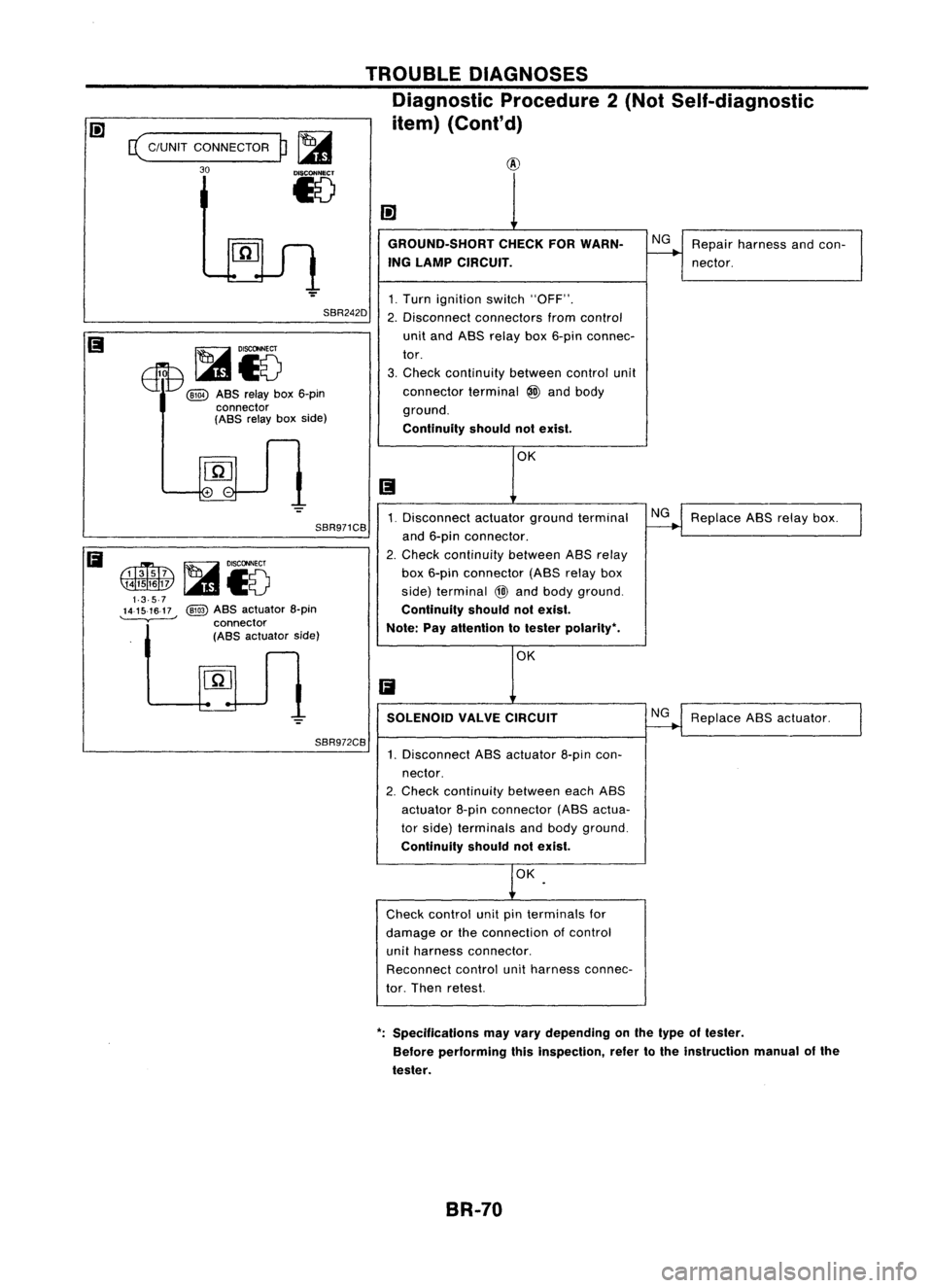
c(
C/UNIT CONNECTOR
30
p~
15
TROUBLE
DIAGNOSES
Diagnostic Procedure2(Not Self-diagnostic
item) (Cont'd)
SBR242D
EIT8
~i5
@QD
ABS
relay box6-pin
connector
(ABS
relayboxside)
SBR971CB
@
ABS
actuator a-pin
connector
(ABS
actuator side)
SBR972CB GROUND-SHORT
CHECKFORWARN-
ING LAMP CIRCUIT.
1. Turn ignition switch"OFF".
2. Disconnect connectors fromcontrol
unit and ABS relay box6-pin connec-
tor.
3. Check continuity betweencontrolunit
connector terminal
@J
and body
ground.
Continuity shouldnotexist.
OK
1. Disconnect actuatorgroundterminal
and 6-pin connector.
2. Check continuity betweenASSrelay
box 6-pin connector (ABSrelaybox
side) terminal
@
and body ground.
Continuity shouldnotexist.
Note: Payattention totester polarity •.
OK
Ii
SOLENOID VALVECIRCUIT
1. Disconnect ABSactuator 8-pincon-
nector.
2. Check continuity betweeneachABS
actuator 8-pinconnector (ABSactua-
tor side) terminals andbody ground.
Continuity shouldnotexist.
OK
Check control unitpinterminals for
damage orthe connection ofcontrol
unit harness connector.
Reconnect controlunitharness connec-
tor. Then retest.
NG
NG NG
Repair
harness andcon-
nector.
Replace ABSrelay box.
Replace ABSactuator.
•. Specifications mayvary depending onthe type oftester.
Before performing thisinspection, refertothe instruction manualofthe
tester.
BR-70