1995 NISSAN ALMERA N15 check engine
[x] Cancel search: check enginePage 921 of 1701
TROUBLEDIAGNOSIS FORNON-DETECTABLE ITEMS
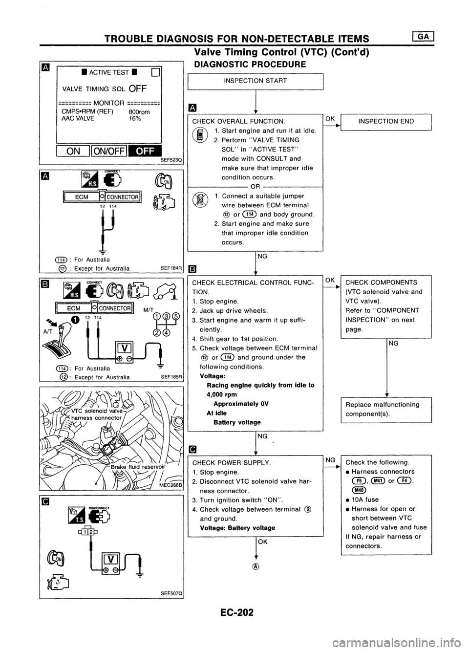
Valve Timing Control (VTC)(Cant'd)
DIAGNOSTIC PROCEDURE
INSPECTION START
m
CHECK OVERALL FUNCTION.
~
INSPECTION
END
00
1.
Start engine andrunitat idle.
2. Perform "VALVETIMING
SOL" in"ACTIVE TEST"
mode withCONSULT and
make surethatimproper idle
condition occurs.
OR
00
1.
Connect asuitable jumper
wire between ECMterminal
@
or
@
andbody ground.
2. Start engine andmake sure
that improper idlecondition
occurs.
NG
iii
CHECK ELECTRICAL CONTROLFUNC-OK
CHECK COMPONENTS
TION.
-+
(VTCsolenoid valveand
1. Stop engine. VTC
valve).
2. Jack updrive wheels. Refer
to"COMPONENT
3. Start engine andwarm itup suffi- INSPECTION"
onnext
ciently. page.
4. Shift gearto1st position.
NG
5. Check voltage between ECMterminal
@
or
@
andground underthe
following conditions.
Voltage: Racing engine quickly fromidleto
4,000 rpm
Approximately OV
Replacemalfunctioning
At idle
component(s).
Battery voltage
NG
.
[!J
CHECK POWER SUPPLY. NG
Check thefollowing.
1. Stop engine.
~
•Harness connectors
2. Disconnect VTCsolenoid valvehar- QD,@or@,
ness connector.
@
3. Turn ignition switch"ON". •
10A fuse
4. Check voltage between terminal
@
•
Harness foropen or
and ground. short
between VTC
Voltage: Batteryvoltage
solenoid
valveandfuse
OK If
NG, repair harness or
connectors.
SEF185R
SEF507Q
SEF184R
M/T
~r5 ~
~£)
II
ECM
~CONNECTORII
12 114
~
ON
II
ON/OFF
IEDI
SEF523Q
•
ACTIVE TEST.
0
VALVE TIMING SOL
OFF
==========
MONITOR
==========
CMPS.RPM (REF)800rpm
AAC VALVE 16%
@):
ForAustralia
@:
Except forAustralia
@):
ForAustralia
12 :Except forAustralia
~i)~ID~
II
ECM
NCONNECTORII
A~fl "'"
~
EC-202
Page 927 of 1701
Referto"TROUBLE
DIAGNOSES" inHA sec-
tion.
Check thefollowing.
• Harness connectors
QD,@
• Harness connectors
@,@
• Harness foropen or
short between IACV-
AAC valve orIACV-
FICO solenoid valve
harness connector and
air conditioner relay
If NG, repair harness or
connectors.
O~L.-
__I_N_S_P_E_CT_I_O_N_E_N_D __
NG
NG
NG
INSPECTION
START
DIAGNOSTIC
PROCEDURE
Check ifair conditioner compressor
functions normally.
OK
OK
CHECK
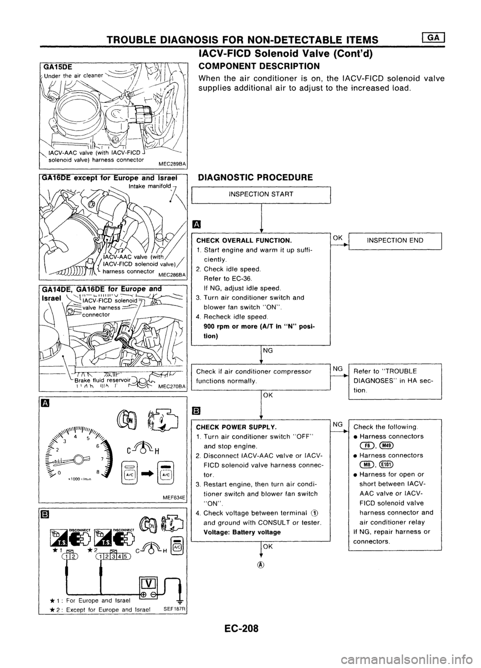
POWER SUPPLY.
1. Turn airconditioner switch"OFF"
and stop engine.
2. Disconnect IACV-AACvalveorIACV-
FICO solenoid valveharness connec-
tor.
3. Restart engine, thenturnaircondi-
tioner switch andblower fanswitch
"ON".
4. Check voltage between terminal
(1)
and ground withCONSULTor tester.
Voltage: Batteryvoltage
SEF187R
MEC289BA
MEF634E
TROUBLE
DIAGNOSIS FORNON-DETECTABLE ITEMS
IACV-FICD SolenoidValve(Cont'd)
COMPONENT DESCRIPTION
When theairconditioner ison, the IACV-FICD solenoidvalve
supplies additional airtoadjust tothe increased load.
~n
* 1: For Europe andIsrael ~
t
* 2: Except forEurope andIsrael
GA14DE,
GA16DEforEurope an
Israel
~'IACV_FIICI~'~O~~'d~
(\ ~valve harness~
~ connector
/
GA
6DE except forEurope andIsrael
'""k,
mM,o"l \
~m
[' ~.CHECKOVERALL FUNCTION.
1. Start engine andwarm itup suffi-
{ iAcv-AAC valve(with / ciently.
IACV-FICD solenoidvalve)
harness connector MEC286BA 2.Check idlespeed.
Refer toEC-36.
If NG, adjust idlespeed.
3. Turn airconditioner switchand
blower fanswitch "ON".
4. Recheck idlespeed.
900 rpm ormore (AITin
"N"
posi-
tion)
EC-208
Page 940 of 1701
TROUBLEDIAGNOSIS FORNON-DETECTABLE ITEMS~
Torque Converter ClutchSolenoid Valve(Cont'd)
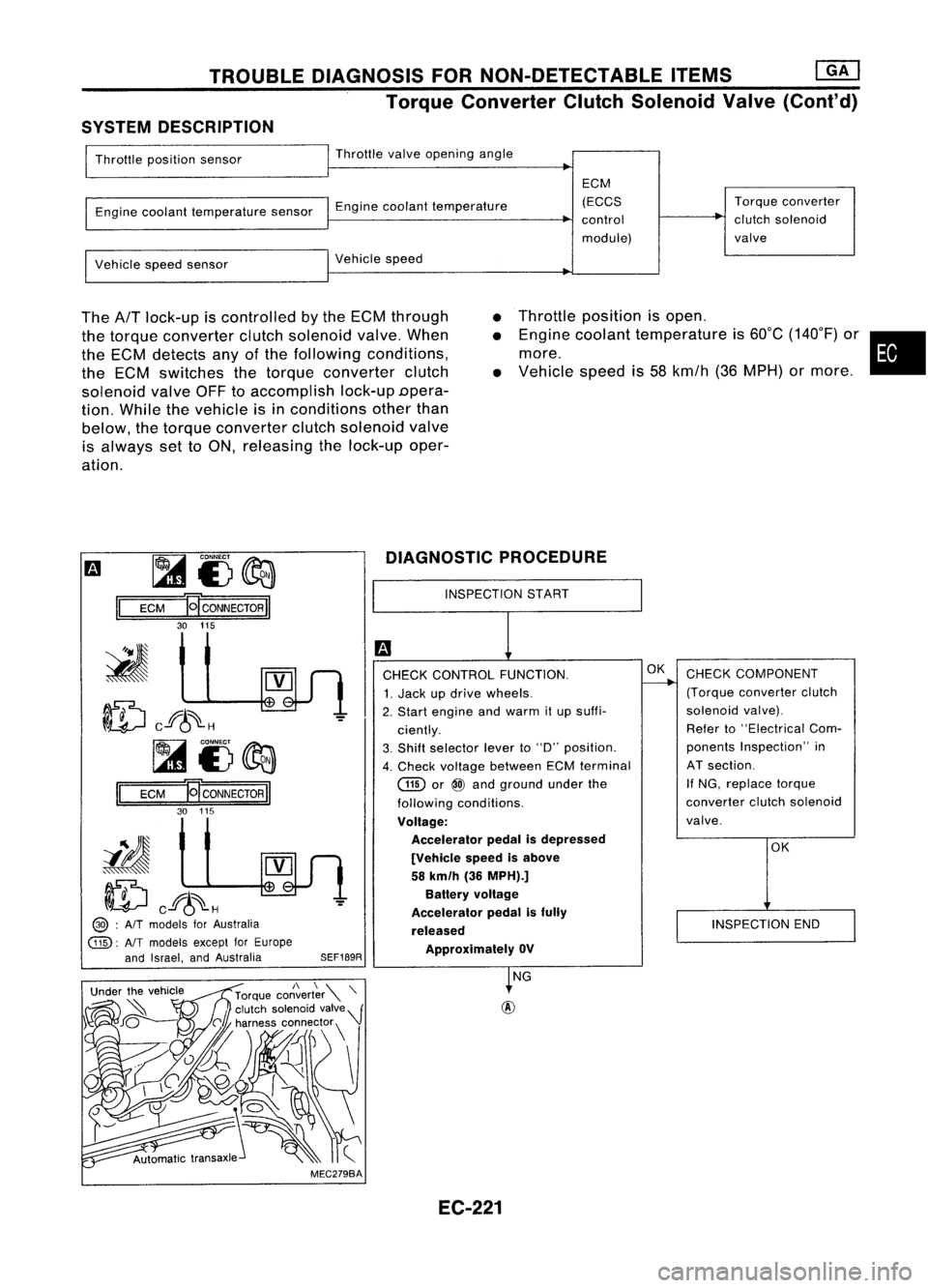
SYSTEM DESCRIPTION
Throttle position sensor Throttle
valveopening angle
Engine coolant temperature sensorEnginecoolant temperature ECM
(ECCS
control
module) Torque
converter
clutch solenoid
valve
Vehicle speedsensor Vehicle
speed
The
AfT
lock-up iscontrolled bythe ECM through
the torque converter clutchsolenoid valve.When
the ECM detects anyofthe following conditions,
the ECM switches thetorque converter clutch
solenoid valveOFFtoaccomplish lock-upDpera-
tion. While thevehicle isin conditions otherthan
below, thetorque converter clutchsolenoid valve
is always settoON, releasing thelock-up oper-
ation.
•
•
•
Throttle
position isopen .
Engine coolant temperature is60°C (140°F) or•
more.
Vehicle speedis58 kmfh (36MPH) ormore .
m ~
i3~
II
ECM
HCONNECTORII
30 115
ID
cf6~H
~i3~
II
ECM E
CONNECTOR
II
30 115
iIJ
ID
cf6~H
@> :
AIT
models forAustralia
@:
AlTmodels exceptforEurope
and Israel, andAustralia
SEF189RDIAGNOSTIC
PROCEDURE
INSPECTION START
CHECK CONTROL FUNCTION.
1. Jack updrive wheels.
2. Start engine andwarm itup suffi-
ciently.
3. Shift selector leverto"D" position.
4. Check voltage between ECMterminal
GID
or
@
and ground underthe
following conditions.
Voltage: Accelerator pedalisdepressed
[Vehicle speedisabove
58 km/h (36MPH).]
Battery voltage
Accelerator pedalisfully
released ApprOXimately OV
OK
CHECK COMPONENT
(Torque converter clutch
solenoid valve).
Refer to"Electrical Com-
ponents Inspection" in
AT section.
If NG, replace torque
converter clutchsolenoid
valve.
OK
INSPECTION END
MEC279BA NG
EC-221
Page 941 of 1701
![NISSAN ALMERA N15 1995 Service Manual TROUBLEDIAGNOSIS FORNON-DETECTABLE ITEMS
@]
Torque Converter ClutchSolenoid Valve(Cont'd)
@
@ :
AIT
models forAustralia
@:
NTmodels exceptforEurope
and Israel, andAustralia
I!J
1
CHECK POW NISSAN ALMERA N15 1995 Service Manual TROUBLEDIAGNOSIS FORNON-DETECTABLE ITEMS
@]
Torque Converter ClutchSolenoid Valve(Cont'd)
@
@ :
AIT
models forAustralia
@:
NTmodels exceptforEurope
and Israel, andAustralia
I!J
1
CHECK POW](/manual-img/5/57349/w960_57349-940.png)
TROUBLEDIAGNOSIS FORNON-DETECTABLE ITEMS
@]
Torque Converter ClutchSolenoid Valve(Cont'd)
@
@ :
AIT
models forAustralia
@:
NTmodels exceptforEurope
and Israel, andAustralia
I!J
1
CHECK POWER SUPPLY. NG
Check thefol/owing.
1. Stop engine.
--.--..
•Harness connectors
2. Disconnect torqueconverter clutch
@),
solenoid valveharness connector. •10A fuse
3. Turn ignition switch"ON".
•Harness foropen or
4. Check voltage between terminal
@
shortbetween torque
and ground. converterclutchsole-
Voltage: Batteryvoltage
noidvalve andfuse
" NG, repair harness or
OK connectors.
[;J
CHECK OUTPUT SIGNALCIRCUIT. NG
Check thefollowing.
1. Turn ignition switch"OFF".
--.--..
•Harness connectors
2. Disconnect ECMharness connector.
aD,@
3. Check harness continuity between •Harness connectors
ECM terminal
(ill)
or
@
and termi-
@,@!)
nal (D. •Harness connectors
Continuity shouldexist.
@),@D
" OK, check harness forshort. •
Harness foropen or
short between ECM
OK andtorque converter
clutch solenoid valve
If
NG, repair harness or
connectors.
CHECK COMPONENT NG
Replace torqueconverter
(Torque converter clutchsolenoid
~
clutchsolenoid valve.
valve).
Refer to"Electrical Components
Inspection" inAT section.
OK
Disconnect andreconnect harnesscon-
nectors inthe circuit. Thenretest.
Trouble isnot fixed.
Check ECMpinterminals fordamage
or the connection ofECM harness con-
nector. Reconnect ECMharness con-
nector andretest.
.
INSPECTION END
SEF190R
SEF513Q
rilio
ECM
HCONNECTORII
115 30
~i5
~
II
EC-222
Page 957 of 1701
EVAPORATIVEEMISSIONSYSTEM
Description
yAir.. Fuelvapor
EGR
valve
&
EVAP canister purgecontrol
solenoid valve
-
EVAP canister
Vapor
ventline
-
Fuel fillercap
with vacuum
relief valve
t
Fuel tank
MEF609DC
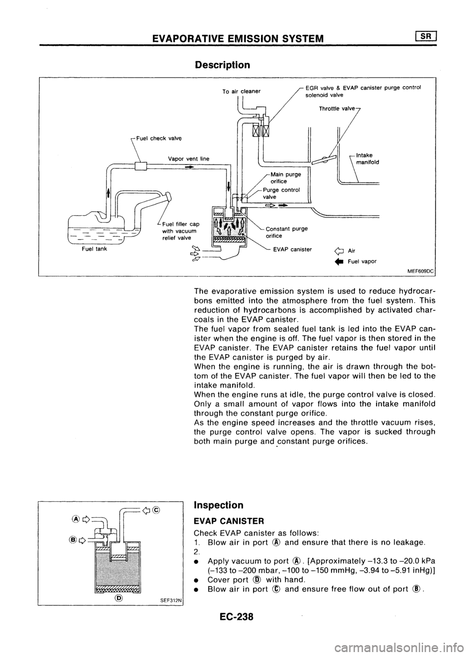
The evaporative emissionsystemisused toreduce hydrocar-
bons emitted intotheatmosphere fromthefuel system. This
reduction ofhydrocarbons isaccomplished byactivated char-
coals inthe EVAP canister.
The fuelvapor fromsealed fueltank isled into theEVAP can-
ister when theengine isoff. The fuelvapor isthen stored inthe
EVAP canister. TheEVAP canister retainsthefuel vapor until
the EVAP canister ispurged byair.
When theengine isrunning, theairisdrawn through thebot-
tom ofthe EVAP canister. Thefuelvapor willthen beled tothe
intake manifold.
When theengine runsatidle, thepurge control valveisclosed.
Only asmall amount ofvapor flowsintotheintake manifold
through theconstant purgeorifice.
As the engine speedincreases andthethrottle vacuum rises,
the purge control valveopens. Thevapor issucked through
both main purge and.constant purgeorifices.
Inspection
EVAP CANISTER
Check EVAPcanister asfollows:
1. Blow airinport
@
and ensure thatthere isno leakage.
2.
• Apply vacuum toport
@.
[Approximately
-13.3
to
-20.0
kPa
(-133
to
-200
mbar,
-100
to
-150
mmHg,
-3.94
to
-5.91
inHg)]
• Cover port
CID
with hand.
• Blow airinport
@
and ensure freeflow outofport
@.
SEF312N
EC-238
Page 959 of 1701
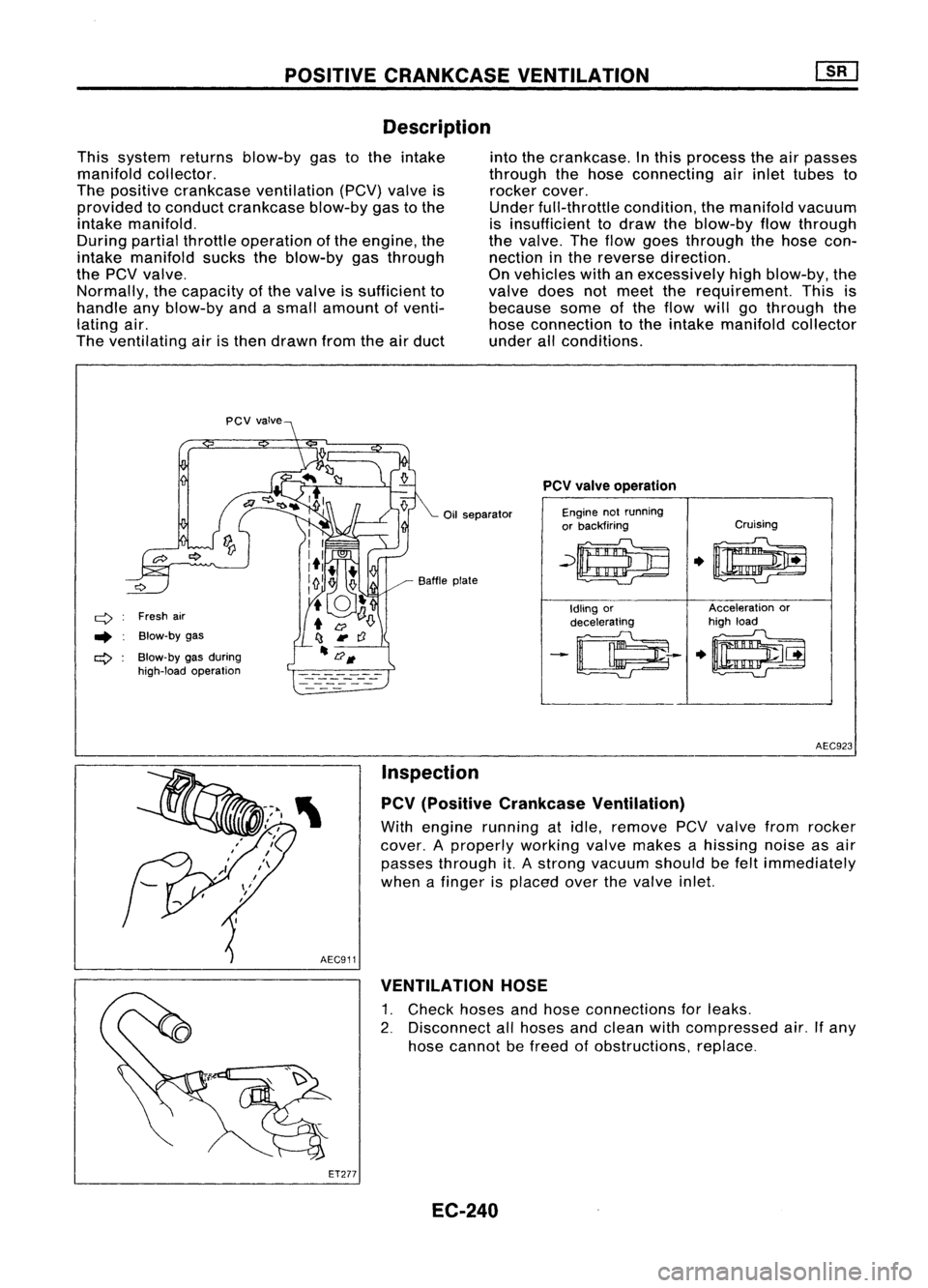
POSITIVECRANKCASE VENTILATION
Description
This system returnsblow-by gastothe intake
manifold collector.
The positive crankcase ventilation (PCV)valveis
provided toconduct crankcase blow-bygastothe
intake manifold.
During partialthrottle operation ofthe engine, the
intake manifold suckstheblow-by gasthrough
the
pev
valve.
Normally, thecapacity ofthe valve issufficient to
handle anyblow-by andasmall amount ofventi-
lating air.
The ventilating airisthen drawn fromtheairduct into
thecrankcase. Inthis process theairpasses
through thehose connecting airinlet tubes to
rocker cover.
Under full-throttle condition,themanifold vacuum
is insufficient todraw theblow-by flowthrough
the valve. Theflow goes through thehose con-
nection inthe reverse direction.
On vehicles withanexcessively highblow-by, the
valve doesnotmeet therequirement. Thisis
because someofthe flow willgothrough the
hose connection tothe intake manifold collector
under allconditions.
Oil separator
q
Freshair
.. Blow-by gas
ct>
Blow-by gasduring
high-load operation Baffle
plate
PCV
valve operation
Engine notrunning
or backfiring Cruising
~~
.0
Idling or Acceleration
or
decelerating high
load
-~--
.~
AEC923
Inspection
PCV (Positive Crankcase Ventilation)
With engine running atidle, remove PCVvalve fromrocker
cover. Aproperly workingvalvemakes ahissing noiseasair
passes through it.Astrong vacuum shouldbefelt immediately
when afinger isplaced overthevalve inlet.
AEC911 VENTILATION HOSE
1. Check hosesandhose connections forleaks.
2. Disconnect allhoses andclean withcompressed air.Ifany
hose cannot befreed ofobstructions, replace.
ET277 EC-240
Page 960 of 1701
~U5e
box
~~~
~11~1-
Datalinkconnector ~"
for CONSULT
t=====/
• FUEL PRESRELEASE. D
FUEL PUMP WillSTOP BY
TOUCHING STARTDURING
IDLE.
CRANK AFEW TIMES AFTER
ENGINE STALL
---S-T~-RT--
BASIC
SERVICE PROCEDURE
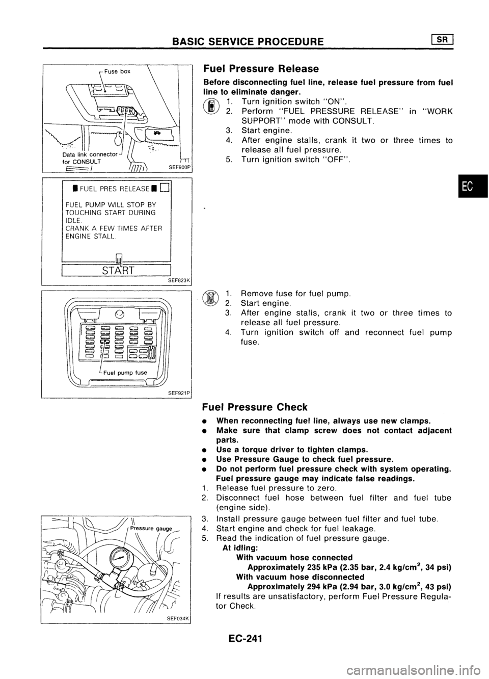
Fuel Pressure Release
Before disconnecting fuelline, release fuelpressure fromfuel
line toeliminate danger.
~ 1.Turn ignition switch"ON".
\J!I}
2.Perform "FUELPRESSURE RELEASE"in"WORK
SUPPORT" modewithCONSULT.
3. Start engine.
4. After engine stalls,crankittwo orthree times to
release allfuel pressure.
5. Turn ignition switch"OFF".
•
@ ~:
3.
SEF823K
SEF921P
SEF034K
Remove
fuseforfuel pump.
Start engine.
After engine stalls,crank
it
two orthree times to
release allfuel pressure.
4. Turn ignition switchoffand reconnect fuelpump
fuse.
Fuel Pressure Check
• When reconnecting fuelline, always usenew clamps.
• Make surethatclamp screwdoesnotcontact adjacent
parts.
• Use atorque drivertotighten clamps.
• Use Pressure Gaugetocheck fuelpressure.
• Donot perform fuelpressure checkwithsystem operating.
Fuel pressure gaugemayindicate falsereadings.
1. Release fuelpressure tozero.
2. Disconnect fuelhose between fuelfilter andfuel tube
(engine side).
3. Install pressure gaugebetween fuelfilter andfuel tube.
4. Start engine andcheck forfuel leakage.
5. Read theindication offuel pressure gauge.
At idling:
With vacuum hoseconnected
Approximately 235kPa (2.35 bar,2.4kg/cm
2,
34psi)
With vacuum hosedisconnected
Approximately 294kPa (2.94 bar,3.0kg/cm
2,
43psi)
If
results areunsatisfactory, performFuelPressure Regula-
tor Check.
EC-241
Page 961 of 1701
BASICSERVICE PROCEDURE
SEF310R
Vacuum
Fuelpressure
.... L
To
pressure regulator
SEF718B
'nsu'a,or~7
a-ring~1 ~
~> ~
InsUlalor~7
OJ'
Om~riJ$ _.
~lnjeCIOr
kJ
Insulator
11+-
1
~'I"
Localeplate
•. onthis side.
a-ring .
I
FuellUbe~i '.
assembly ,.
~'nsulator
I
SEF616N
MEC710B Fuel
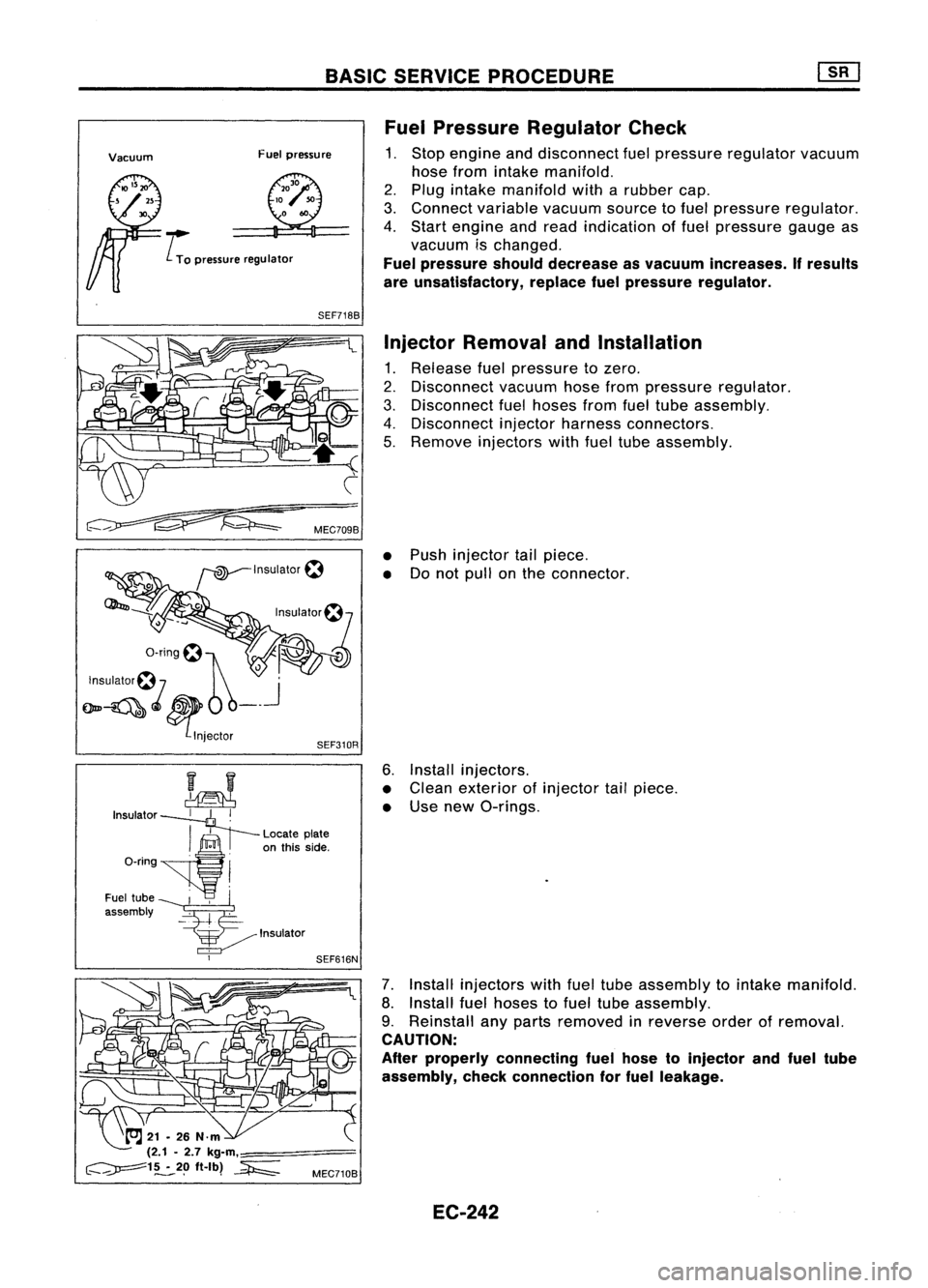
Pressure Regulator Check
1. Stop engine anddisconnect fuelpressure regulator vacuum
hose from intake manifold.
2. Plug intake manifold witharubber cap.
3. Connect variable vacuumsourcetofuel pressure regulator.
4. Start engine andread indication offuel pressure gaugeas
vacuum ischanged.
Fuel pressure shoulddecrease asvacuum increases. Ifresults
are unsatisfactory, replacefuelpressure regulator.
Injector Removal andInstallation
1. Release fuelpressure tozero.
2. Disconnect vacuumhosefrompressure regulator.
3. Disconnect fuelhoses fromfueltube assembly.
4. Disconnect injectorharness connectors.
5. Remove injectors withfueltube assembly.
• Push injector tailpiece.
• Donot pull onthe connector.
6. Install injectors.
• Clean exterior ofinjector tailpiece.
• Use new O-rings.
7. Install injectors withfueltube assembly tointake manifold.
8. Install fuelhoses tofuel tube assembly.
9. Reinstall anyparts removed inreverse orderofremoval.
CAUTION:
After properly connecting fuelhose toinjector andfuel tube
assembly, checkconnection forfuel leakage.
EC-242