1995 NISSAN ALMERA N15 check engine
[x] Cancel search: check enginePage 983 of 1701

TROUBLEDIAGNOSIS -General Description
Sensors
~ ECMActuators
~~.~ MEF036D
SEF234G Introduction
The engine hasanECM tocontrol majorsystems suchasfuel
control, ignitioncontrol, idleaircontrol system, etc.The ECM
accepts inputsignals fromsensors andinstantly drivesactua-
tors. Itis essential thatboth input andoutput signals areproper
and stable. Atthe same time,itis important thatthere areno
problems suchasvacuum leaks,fouled sparkplugs, orother
problems withtheengine.
It is much moredifficult todiagnose aproblem thatoccurs
intermittently ratherthancontinuously. Mostintermittent prob-
lems arecaused bypoor electric connections orimproper wir-
ing. Inthis case, careful checking ofsuspected circuitsmay
help prevent thereplacement ofgood parts.
A visual checkonlymaynotfind thecause ofthe problems. A
road testwith CONSULT oracircuit testerconnected shouldbe
performed. Followthe"Work Flow"onthe next page.
Before undertaking actualchecks, takejustafew minutes to
talk with acustomer whoapproaches withadriveability com-
plaint. Thecustomer cansupply goodinformation aboutsuch
problems, especially intermittent ones.Findoutwhat symptoms
are present andunder whatconditions theyoccur. A"Diagnos-
tic Worksheet" liketheexample onEC-267 shouldbeused.
Start yourdiagnosis bylooking for"conventional" problems
first. Thiswillhelp troubleshoot driveabilityproblemsonan
electronically controlledenginevehicle.
EC-264
Page 985 of 1701

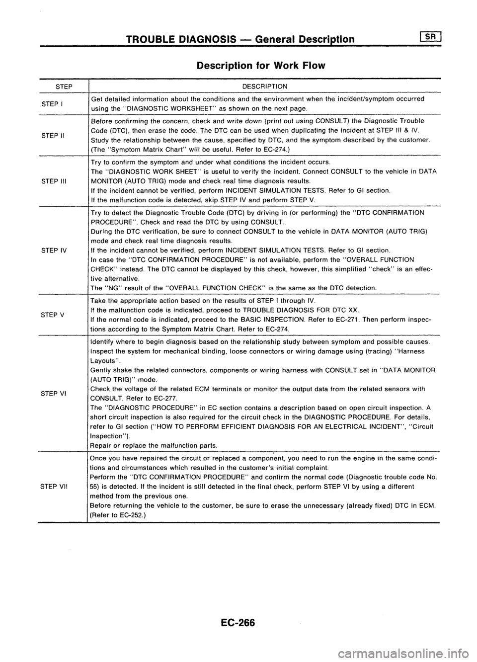
STEP
STEP I
STEP II
STEP III
STEP IV
STEP V
STEP VI
STEP VII
TROUBLE
DIAGNOSIS -General Description
Description forWork Flow
DESCRIPTION
Get detailed information abouttheconditions andtheenvironment whentheincident/symptom occurred
using the"DIAGNOSTIC WORKSHEET" asshown onthe next page.
Before confirming theconcern, checkandwrite down (printoutusing CONSULT) theDiagnostic Trouble
Code (DTC), thenerase thecode. TheDTC canbeused when duplicating theincident atSTEP
1/1
&
IV.
Study therelationship betweenthecause, specified byDTC, andthesymptom described bythe customer.
(The "Symptom MatrixChart" willbeuseful. RefertoEC-274.)
Try toconfirm thesymptom andunder whatconditions theincident occurs.
The "DIAGNOSTIC WORKSHEET" isuseful toverify theincident. ConnectCONSULT tothe vehicle inDATA
MONITOR (AUTOTRIG)modeandcheck realtime diagnosis results.
If the incident cannotbeverified, performINCIDENT SIMULATION TESTS.RefertoGI section.
If the malfunction codeisdetected, skipSTEP IVand perform STEPV.
Try todetect theDiagnostic TroubleCode(DTC) bydriving in(or performing) the"DTC CONFIRMATION
PROCEDURE". Checkandread theDTC byusing CONSULT.
During theDTC verification, besure toconnect CONSULT tothe vehicle inDATA MONITOR (AUTOTRIG)
mode andcheck realtime diagnosis results.
If the incident cannotbeverified, performINCIDENT SIMULATION TESTS.RefertoGI section.
In case the"DTC CONFIRMATION PROCEDURE"isnot available, performthe"OVERALL FUNCTION
CHECK" instead.TheDTC cannot bedisplayed bythis check, however, thissimplified "check"isan effec-
tive alternative.
The "NG" result ofthe "OVERALL FUNCTIONCHECK"isthe same asthe DTC detection.
Take theappropriate actionbasedonthe results ofSTEP Ithrough IV.
If the malfunction codeisindicated, proceedtoTROUBLE DIAGNOSIS FORDTCXX.
If the normal codeisindicated, proceedtothe BASIC INSPECTION. RefertoEC-271. Thenperform inspec-
tions according tothe Symptom MatrixChart.RefertoEC-274.
Identify wheretobegin diagnosis basedonthe relationship studybetween symptom andpossible causes.
Inspect thesystem formechanical binding,looseconnectors orwiring damage using(tracing) "Harness
Layouts".
Gently shaketherelated connectors, components orwiring harness withCONSULT setin"DATA MONITOR
(AUTO TRIG)" mode.
Check thevoltage ofthe related ECMterminals ormonitor theoutput datafrom therelated sensors with
CONSULT. RefertoEC-277.
The "DIAGNOSTIC PROCEDURE" inEC section contains adescription basedonopen circuit inspection. A
short circuit inspection isalso required forthe circuit checkinthe DIAGNOSTIC PROCEDURE. Fordetails,
refer toGI section ("HOWTOPERFORM EFFICIENT DIAGNOSIS FORANELECTRICAL INCIDENT","Circuit
Inspection").
Repair orreplace themalfunction parts.
.
Once youhave repaired thecircuit orreplaced acomponent, youneed torun theengine inthe same condi-
tions andcircumstances whichresulted inthe customer's initialcomplaint.
Perform the"DTC CONFIRMATION PROCEDURE"andconfirm thenormal code(Diagnostic troublecodeNo.
55) isdetected. Ifthe incident isstill detected inthe final check, perform STEPVIby using adifferent
method fromtheprevious one.
Before returning thevehicle tothe customer, besure toerase theunnecessary (alreadyfixed)DTCinECM.
(Refer toEC-252.)
EC-266
Page 988 of 1701
![NISSAN ALMERA N15 1995 Service Manual TROUBLEDIAGNOSIS -General Description
ill]
Diagnostic TroubleCode(DTC) Chart(Cont'd)
x:
Applicable
-: Not applicable
"DTC *1
*2
Check Items CONFIRMATION
"OVERALLFUNC-
Fail ReferencePag NISSAN ALMERA N15 1995 Service Manual TROUBLEDIAGNOSIS -General Description
ill]
Diagnostic TroubleCode(DTC) Chart(Cont'd)
x:
Applicable
-: Not applicable
"DTC *1
*2
Check Items CONFIRMATION
"OVERALLFUNC-
Fail ReferencePag](/manual-img/5/57349/w960_57349-987.png)
TROUBLEDIAGNOSIS -General Description
ill]
Diagnostic TroubleCode(DTC) Chart(Cont'd)
x:
Applicable
-: Not applicable
"DTC *1
*2
Check Items CONFIRMATION
"OVERALLFUNC-
Fail ReferencePage
(Possible Cause) PROCEDURE"
TIONCHECK"
Safe
Quick Ref. QuickRef. System
• Harness orconnectors
(The sensor circuitisopen orshorted.)
• Camshaft positionsensor
RUNNING
--
EC-289
• Starter motor
• Starting systemcircuit(ELsection)
• Dead (Weak) battery
• Harness orconnectors
-
(The sensor circuitisopen orshorted.) RUNNING
RUNNING
X
EC-293
• Mass airflow sensor
• Harness orconnectors
(The sensor circuitisopen orshorted.) IGN:
ON
-
X
EC-297
• Engine coolant temperature sensor
• Harness orconnectors
(The ignition primary circuitisopen orshorted.)
• Power transistor unit RUNNING
--
EC-301
• Camshaft positionsensor
• Camshaft positionsensorcircuit
• Harness orconnectors
(The sensor circuitisopen orshorted.) RUNNING
--
EC-306
• Knock sensor
• Harness orconnectors
(The sensor circuitisopen orshorted.)
-
IGN:
ON
X
EC-309
• Throttle position sensor
• No failure
--
-
-
*2: •The "OVERALL FUNCTIONCHECK"isasimplified andeffective waytoinspect acomponent orcircuit.
In some cases, the"OVERALL FUNCTIONCHECK"isused rather thana"DIAGNOSTIC TROUBLECODECONFIRMA-
TION PROCEDURE".
When noDTC CONFIRMATION PROCEDUREisavailable, the"NG" result ofthe OVERALL FUNCTION CHECKcanbe
considered tomean thesame asaDTC detection .
• During an"NG" OVERALL FUNCTION CHECK,theDTC might notbeconfirmed.
EC-269
•
Page 990 of 1701

TROUBLEDIAGNOSIS -General Descrip_ti_on
1S_R_'
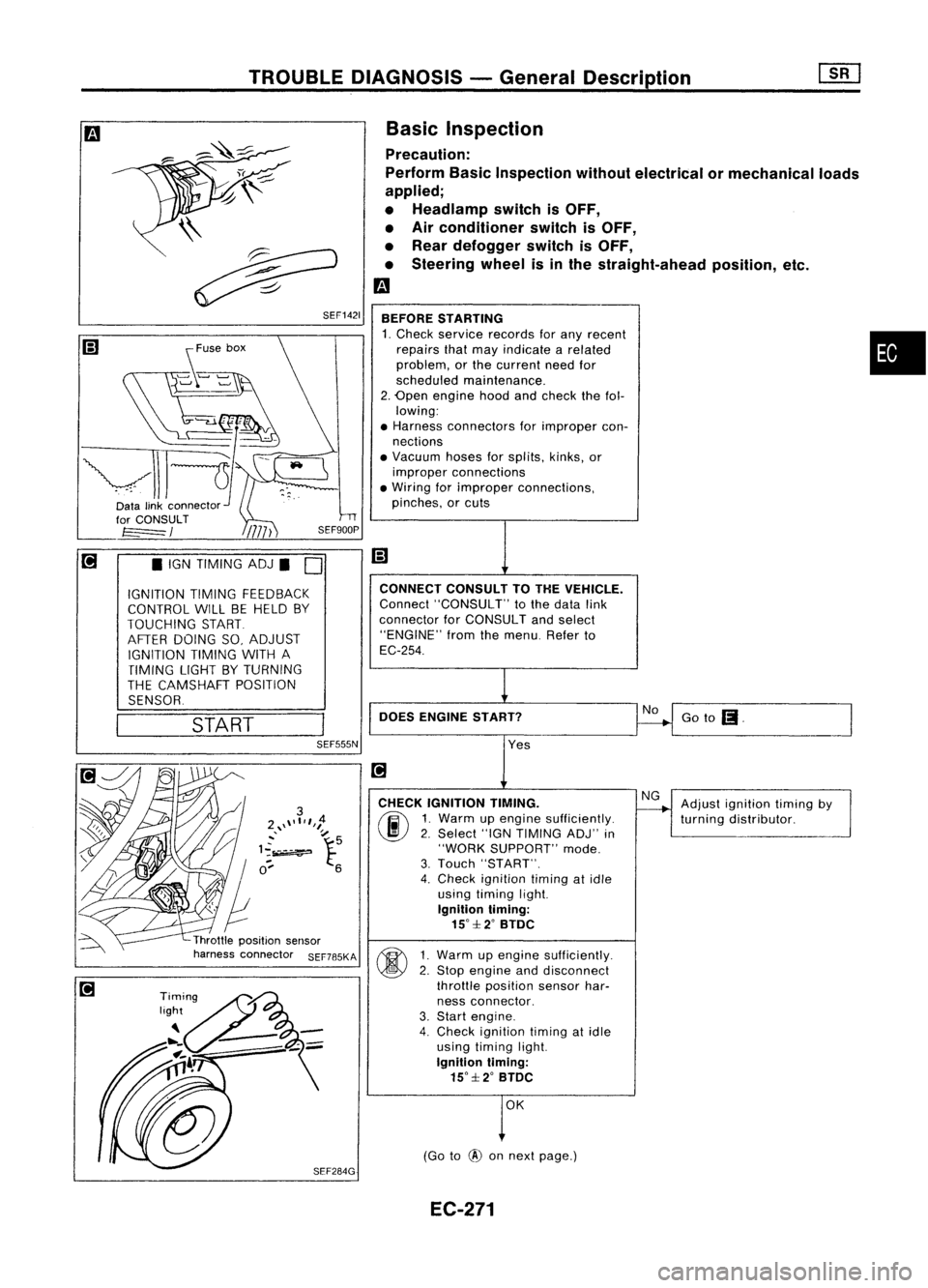
Basic Inspection
Precaution:
Perform BasicInspection withoutelectrical ormechanical loads
applied;
• Headlamp switchisOFF,
• Air conditioner switchisOFF,
• Rear defogger switchisOFF,
• Steering wheelisinthe straight-ahead position,etc.
m
BEFORE STARTING
1. Check service records forany recent •
repairs thatmay indicate arelated
problem, orthe current needfor
scheduled maintenance.
2. Open engine hoodandcheck thefol-
lowing:
• Harness connectors forimproper con-
nections
• Vacuum hosesforsplits, kinks,or
improper connections
• Wiring forimproper connections,
pinches, orcuts
Goto
(I.
No
CONNECT
CONSULTTOTHE VEHICLE.
Connect "CONSULT" tothe data link
connector forCONSULT andselect
"ENGINE" fromthemenu. Referto
EC-254.
DOES ENGINE START?
\\
~
~ SEF1421
START
•
IGN TIMING ADJ.
0
IGNITION TIMINGFEEDBACK
CONTROL WILLBEHELD BY
TOUCHING START
AFTER DOING SO,ADJUST
IGNITION TIMINGWITHA
TIMING LIGHTBYTURNING
THE CAMSHAFT POSITION
SENSOR.
SEF555N
Yes
CHECK IGNITION TIMING.
(ij\
1.Warm upengine sufficiently.
~ 2.Select "IGNTIMING ADJ"in
"WORK SUPPORT" mode.
3. Touch "START".
4. Check ignition timingatidle
using timing light.
Ignition timing:
15°::f:2° BTDC
~ 1Warm upengine sufficiently.
~ 2:
Stop engine anddisconnect
throttle position sensorhar-
ness connector.
3. Start engine.
4. Check ignition timingatidle
using timing light.
Ignition timing:
15°::f:2° BTDC
OK
(Go to
@
onnext page.) Adjust
ignition timingby
turning distributor.
EC-271
Page 991 of 1701
![NISSAN ALMERA N15 1995 Service Manual
I!]
CHECK IDLEADJ. SCREW INITIALSET
NG
Adjust engine speedby
---..
RPM.
turningidleadjusting
00
1.
Select "IGNTIMING ADJ"in screw.
"WORK SUPPORT" mode.
2. When touching "STAR NISSAN ALMERA N15 1995 Service Manual
I!]
CHECK IDLEADJ. SCREW INITIALSET
NG
Adjust engine speedby
---..
RPM.
turningidleadjusting
00
1.
Select "IGNTIMING ADJ"in screw.
"WORK SUPPORT" mode.
2. When touching "STAR](/manual-img/5/57349/w960_57349-990.png)
I!]
CHECK IDLEADJ. SCREW INITIALSET
NG
Adjust engine speedby
---..
RPM.
turningidleadjusting
00
1.
Select "IGNTIMING ADJ"in screw.
"WORK SUPPORT" mode.
2. When touching "START",
does engine speedfallto
750:!: 50rpm
(AfT
in
"N"
posi-
tion)?
OR
00
Does
engine runat750:!: 50rpm
(AfT
In
"N"
position)?
OK
Reconnect throttleposition sensorhar-
ness connector.
Ii
CHECK THROTTLE POSITIONSENSOR
NG
Adjust outputvoltage to
IDLE POSITION.
---..
0.50Vbyrotating throttle
00
1.
Perform ''THRTLPOSSEN
positionsensorbody.
ADJ" in"WORK SUPPORT"
1
mode.
2. Check thatoutput voltage of
RESETIDLEPOSITION
throttle position sensoris
MEMORY.
approx. 0.35to0.65V (Throttle
1.Warm upengine suffi-
valve fullycloses.) and"CLSD ciently.
2. Turn ignition switch
THLIPOSI" stays"ON".
"OFF"andwait at
OR least5seconds.
00
Measure
outputvoltage ofthrot- 3.
Disconnect throttle
position sensorhar-
tie position sensorusing
nessconnector.
voltmeter, andcheck thatitis
4.
Start engine andwait
approx. 0.35toO.65V. (Throttle at
least 5seconds in
"N" position.
valve fullyclosed.)
5.Reconnect throttle
OK • position
sensorhar-
ness connector while
running engine.
~
1
,
THRTL
POSSEN O,52V
SEF165P
•••
ADJMONITOR •••
TROUBLE
DIAGNOSIS -General Description
Basic Inspection (Cont'd)
@
========
MONITOR
========
CMPS.RPM (REF)Orpm
CLSDTHUP ON
Ii
•
THRTL POSSENADJ
.0
I!]
•IGN TIMING ADJ.
0
IGNITION TIMINGFEEDBACK
CONTROL WILLBEHELD BY
TOUCHING START
AFTER DOING SO,ADJUST
IGNITION TIMINGWITHA
TIMING LIGHTBYTURNING
THE CAMSHAFT POSITION
SENSOR
I
START
I
SEF546N
CID
(Go tonext page)
EC-272
Page 992 of 1701

TROUBLEDIAGNOSIS -General Description
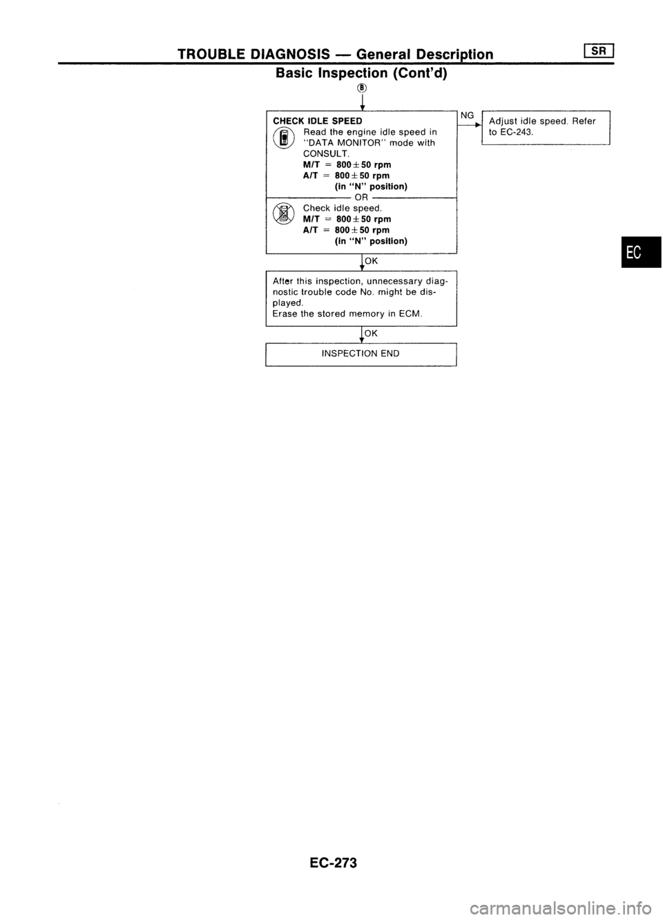
Basic Inspection (Conl'd)
@
CHECK IDLESPEED
(ij\
Readtheengine idlespeed in
~ "DATA MONITOR" modewith
CONSULT.
MfT
=
800:1: 50
rpm
AfT
=
800:1: 50
rpm
(in
uN"
position)
OR
fiY\
Check idlespeed.
~ MfT
=
800:1:50
rpm
AfT =800:1: 50
rpm
(in
uN"
posillon)
OK
After thisinspection, unnecessary diag-
nostic trouble codeNo.might bedis-
played.
Erase thestored memory inECM.
OK
INSPECTION END
EC-273 NG
Adjust idlespeed. Refer
to
EC-243.
•
Page 996 of 1701

TROUBLEDIAGNOSIS -General Description
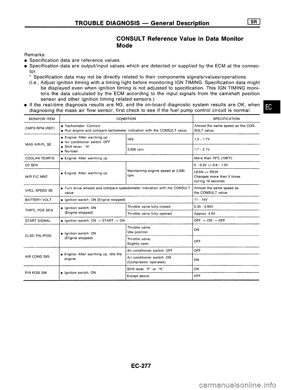
CONSULT Reference ValueinData Monitor
Mode
Remarks:
• Specification dataarereference values.
• Specification dataareoutput/input valueswhicharedetected orsupplied bythe ECM atthe connec-
tor.
*
Specification datamaynotbedirectly relatedtotheir components signals/values/operations.
(Le., Adjust ignition timingwithatiming lightbefore monitoring IGNTIMING. Specification datamight
be displayed evenwhen ignition timingisnot adjusted tospecification. ThisIGNTIMING moni-
tors thedata calculated bythe ECM according tothe input signals fromthecamshaft position
sensor andother ignition timingrelated sensors.)
• Ifthe real-time diagnosis resultsareNG, andtheon-board diagnostic systemresultsareOK, when •
diagnosing themass airflow sensor, firstcheck tosee ifthe fuel pump control circuitisnormal.
MONITOR ITEM CONDITION
SPECIFICATION
CMPS.RPM (REF)•
Tachometer: Connect Almostthesame speed asthe CON-
• Run engine andcompare tachometer indicationwiththeCONSULT value.SULTvalue.
• Engine: Afterwarming up
Idle 1.3-1.7V
MAS AIR/FL SE •
Air conditioner switch:OFF
• Shift lever: "N"
• No-load 2,000
rpm 1.7-2.1V
COOLAN TEMPIS •
Engine: Afterwarming up More
than70°C (15S0F)
02 SEN 0-
0.3V .....0.6 -1.0V
• Engine: Afterwarming up Maintaining
enginespeedat2,000
LEAN
+-->
RICH
MIR
FIC
MNT rpm
Changesmorethan5times
during 10seconds.
VHCL SPEED SE•
Turn drive wheels andcompare speedometer indicationwiththeCONSULT Almostthesame speed as
value the
CONSULT value
BATTERY VOLT •
Ignition switch:ON(Engine stopped) 11
-14V
• Ignition switch:ON Throttle
valvefullyclosed
0.35-0.65V
THRTL
pas
SEN
(Enginestopped)
Throttlevalvefullyopened Approx.4.0V
START SIGNAL •
Ignition switch:ON
->
START
->
ON OFF
->
ON
->
OFF
Throttle valve:
ON
• Ignition switch:ON Idle
position
CLSD THLIPOSI
(Enginestopped)
Throttlevalve:
Slightly open OFF
Air conditioner switch:OFF OFF
AIR COND SIG •
Engine: Afterwarming up,idle the
engine Air
conditioner switch:ON
ON
(Compressor operates)
Shift lever "P"or"N" ON
PIN POSI SW •
Ignition switch:ON
Exceptabove OFF
EC-277
Page 1001 of 1701
![NISSAN ALMERA N15 1995 Service Manual TROUBLEDIAGNOSIS -General Description
[![]
ECM Terminals andReference Value(Cont'd)
ECM inspection table
*Dataarereference
values.
TERMINAL WIRE
ITEM
NO. COLOR CONDITION
'DATA
[Engine isr NISSAN ALMERA N15 1995 Service Manual TROUBLEDIAGNOSIS -General Description
[![]
ECM Terminals andReference Value(Cont'd)
ECM inspection table
*Dataarereference
values.
TERMINAL WIRE
ITEM
NO. COLOR CONDITION
'DATA
[Engine isr](/manual-img/5/57349/w960_57349-1000.png)
TROUBLEDIAGNOSIS -General Description
[![]
ECM Terminals andReference Value(Cont'd)
ECM inspection table
*Dataarereference
values.
TERMINAL WIRE
ITEM
NO. COLOR CONDITION
'DATA
[Engine isrunninQ]
0.2-0.3V
L Idle speed
1
W/B
Ignitionsignal
IEngineisrunning.1
L Engine speedis2,000 rpm. Approximately
0.7V
2 LlOR Tachometer IEngine
isrunning]
Approximately0.9V
L Idle speed
3 GY/R
Ignitioncheck !Engine
isrunning.1
Approximately13V
L Idle speed
IEngine isrunning.1
I
Ilgnition switch"OFF"I
0-1V
ECCS relay(Self-shut- L
For afew seconds afterturning ignition
4
WIG
switch"OFF"
off)
Ilgnitionswitch"OFF"I
BATTERYVOLTAGE
L Afew seconds afterturning ignition switch
(11-14V)
"OFF" andthereafter
6
B/W
ECCSground IEngine
isrunning.1
Engineground
L Idle speed
7
G/B
Approximately13.5V
14
G/W
Datalinkconnector forIEngine
isrunning.1
ApproximatelyOV
15 GY/L CONSULT
LIdle speed Approximately
2.5V
23
G/R
ApproximatelyOV
IEngine isrunning.1
BATTERYVOLTAGE
Cooling fanrelay (Low L
Cooling fanisnot operating. (11
-14V)
9 LG/R
speed) IEngineisrunning.1
L Cooling fanisoperating. Approximately
OV
IEngine isrunning.1
BATTERYVOLTAGE
Cooling fanrelay
t
Cooling fanisnot operating.
(11-14V)
10 LG Cooling
fanisoperating atlow speed.
(High speed)
IEngineisrunning.1
L Cooling fanisoperating athigh speed. Approximately
OV
IEngine isrunning.1
L Both
A/C
switch andblower fanswitch areApproximately
OV
11 Y Airconditioner relay "ON".
IEngine isrunning.1
BATTERYVOLTAGE
LAIC switchis"OFF". (11
-14V)
13
B/W
ECCSground IEngine
isrunning.1
Engineground
L Idle speed
EC-282