1995 NISSAN ALMERA N15 check engine
[x] Cancel search: check enginePage 1028 of 1701
TROUBLEDIAGNOSIS FORDTC43
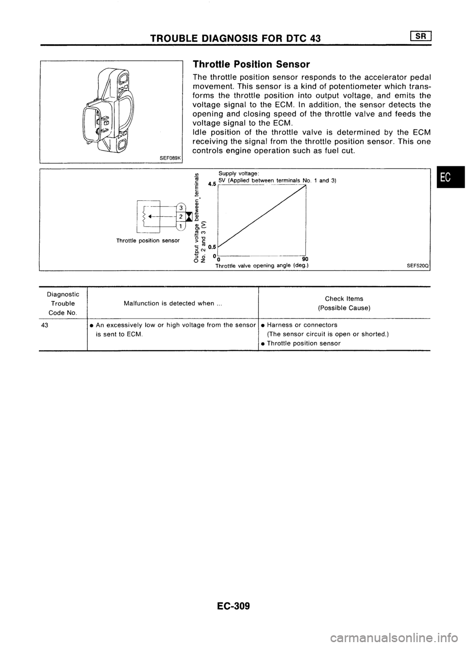
SEF089K Throttle
Position Sensor
The throttle position sensorresponds tothe accelerator pedal
movement. Thissensor isakind ofpotentiometer whichtrans-
forms thethrottle position intooutput voltage, andemits the
voltage signaltothe ECM. Inaddition, thesensor detects the
opening andclosing speedofthe throttle valveandfeeds the
voltage signaltothe ECM.
Idle position ofthe throttle valveisdetermined
by
the ECM
receiving thesignal fromthethrottle position sensor.Thisone
controls engineoperation suchasfuel cut.
•
SEF520Q
VI
Supplyvoltage:
~ 4.55V (Applied be~VoIee~_terminals NO.1and3)
.~
2
[f~.. ~
L
L
1
&c
~ ~M
Throttle position sensor g
-g
:; ~ 0.5
0.
8 ~
00 -~---_. 90
Throttle valveopening angle(deg.)
Diagnostic Trouble
Code No. Malfunction
isdetected when... Check
Items
(Possible Cause)
43
•
An excessively loworhigh voltage fromthesensor •Harness orconnectors
is sent toECM. (Thesensor circuitisopen orshorted.)
• Throttle position sensor
EC-309
Page 1031 of 1701
Repairharness orcon-
nectors.
NG
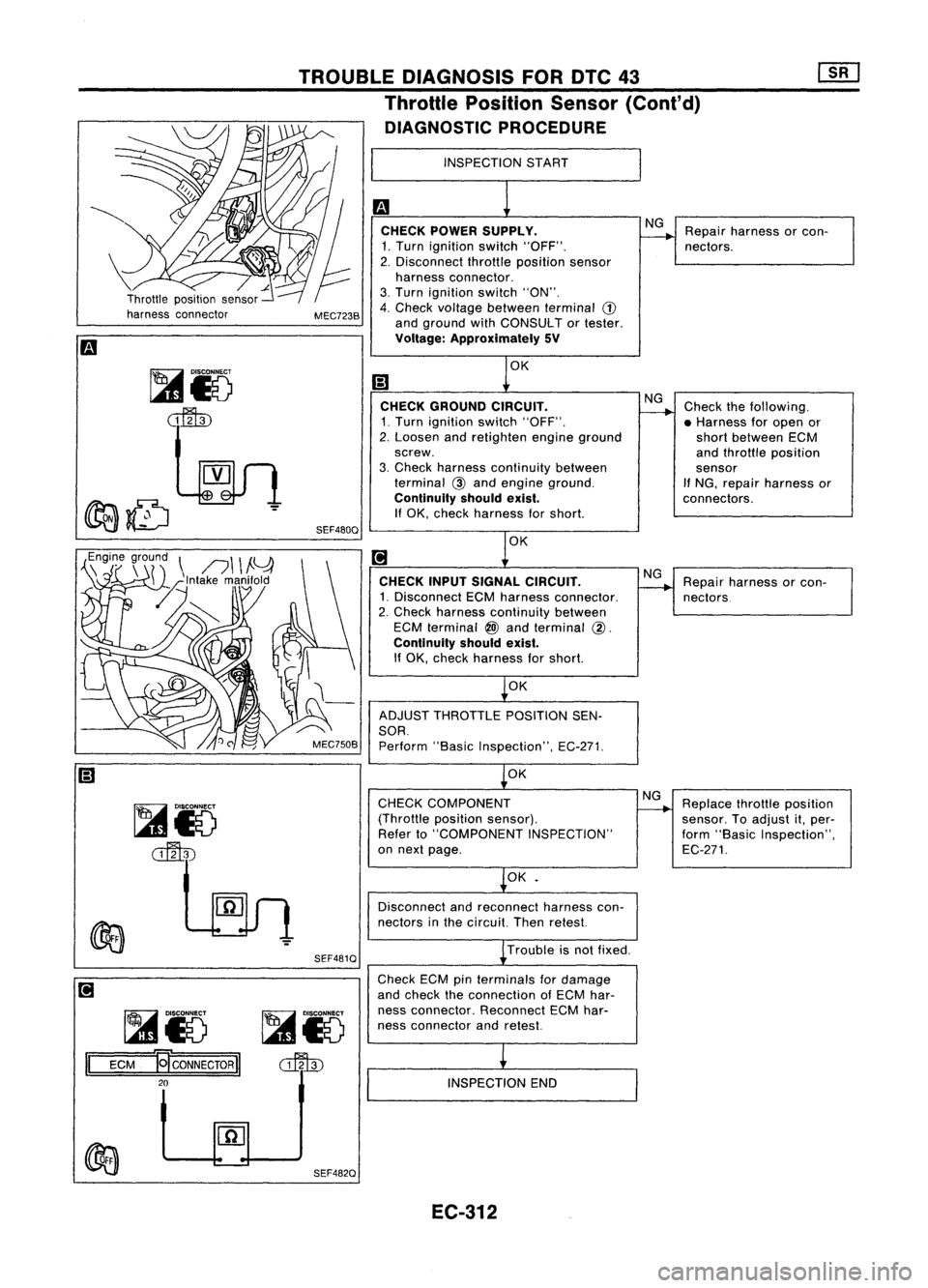
CHECK POWER SUPPLY.
1. Turn ignition switch"OFF".
2. Disconnect throttleposition sensor
harness connector.
3. Turn ignition switch"ON".
4. Check voltage between terminal
(1)
and ground withCONSULT ortester.
Voltage: Approximately 5V
INSPECTION
START
TROUBLE
DIAGNOSIS FORDTC43
Throttle Position Sensor(Cont'd)
DIAGNOSTIC PROCEDURE
MEC723B
,,~n~7
r~r~\
n\ \
!Y
-z~lntake manifold
[L~
SEF480QOK
CHECK GROUND CIRCUIT.
1. Turn ignition switch"OFF".
2. Loosen andretighten engineground
screw.
3. Check harness continuity between
terminal
@
and engine ground.
Continuity shouldexist.
If
OK, check harness forshort.
OK
CHECK INPUTSIGNAL CIRCUIT.
1. Disconnect ECMharness connector.
2. Check harness continuity between
ECM terminal
@)
and terminal
@.
Continuity shouldexist.
If OK, check harness forshort.
OK
ADJUST THROTTLE POSITIONSEN-
SOR.
Perform "BasicInspection", EC-271.
OK NG
NG
Check
thefollowing.
• Harness foropen or
short between ECM
and throttle position
sensor
If
NG, repair harness or
connectors.
Repair harness orcon-
nectors
~io
~ SEF481Q
CHECK
COMPONENT
(Throttle positionsensor).
Refer to"COMPONENT INSPECTION"
on next page.
OK•
Disconnect andreconnect harnesscon-
nectors inthe circuit. Thenretest.
Trouble isnot fixed.
NG
Replace throttleposition
sensor. Toadjust it,per-
form "Basic Inspection",
EC-271.
~io ~i5
II
ECM
~CONNECTORII
o::fl\])
20
Check
ECMpinterminals fordamage
and check theconnection ofECM har-
ness connector. Reconnect ECMhar-
ness connector andretest.
INSPECTION END
SEF482Q EC-312
Page 1037 of 1701
TROUBLEDIAGNOSIS FORNON-DETECTABLE ITEMS
Start Signal (Cont'd)
DIAGNOSTIC PROCEDURE
• START SIGNAL CKT•
INSPECTIONSTART
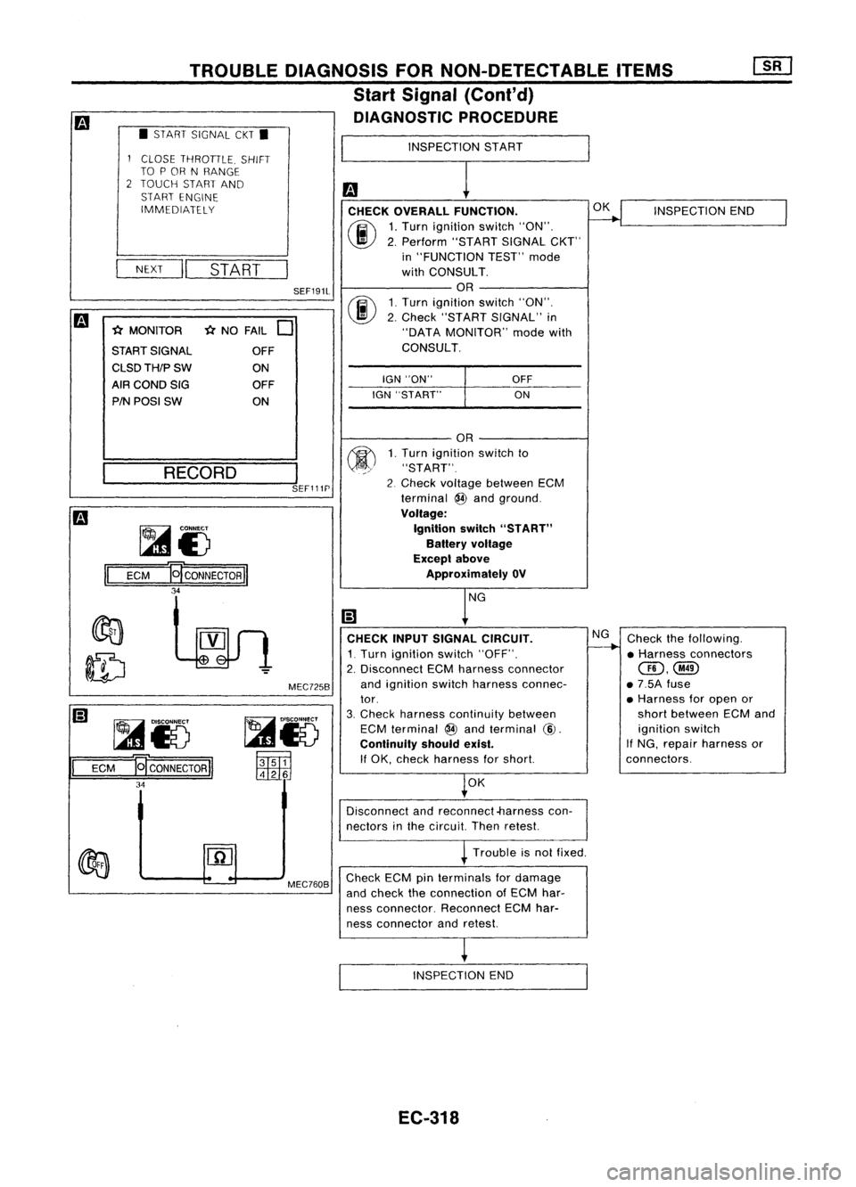
fa CHECK OVERALL FUNCTION.
(ij\
1,Turn ignition switch"ON",
~ 2,Perform "STARTSIGNALCKT"
in "FUNCTION TEST"mode
with CONSULT,
OR
rif\
1,Turn ignition switch"ON",
~ 2,Check "START SIGNAL" in
"DATA MONITOR" modewith
CONSULT,
1
CLOSE THROTILE, SHIFT
TO POR NRANGE
2 TOUCH STARTAND
START ENGINE
IMMEDIATELY
NEXT
II
START
fa
-(:(MONITOR -(:(NO FAIL
0
START SIGNAL OFF
CLSDTH/PSW ON
AfRCONDSIG OFF
PIN POSI SW ON
SEF191L
IGN"ON"
IGN "START"
OFF
ON OK
INSPECTION END
___ RE_C_O_R_D __
I
SEF111P
Checkthefollowing,
• Harness connectors
@,@
• 7,5A fuse
• Harness foropen or
short between ECMand
ignition switch
If NG, repair harness or
connectors,
NG
CHECK INPUTSIGNAL CIRCUIT.
1, Turn ignition switch"OFF",
2, Disconnect ECMharness connector
and ignition switchharness connec-
tor,
3, Check harness continuity between
ECM terminal
@
and terminal
@,
Continuity shouldexist.
If OK, check harness forshort
OK
OR
1, Turn ignition switchto
"START",
2 Check voltage between ECM
terminal
@
and ground,
Voltage: Ignition switch"START"
Battery voltage
Exceplabove
Approximately OV
MEC725B
~15
~
t:1tlliJ
~i3
ECM
E[CONNECTORII
34
~
II
ECM ~CONNECTORI
34
Disconnectandreconnect-harness con-
nectors inthe circuit Thenretest
Trouble isnot fixed,
MEC760B
Check
ECMpinterminals fordamage
and check theconnection ofECM har-
ness connector, ReconnectECMhar-
ness connector andretest
INSPECTION END
EC-318
Page 1040 of 1701
•
INSPECTION
START
m
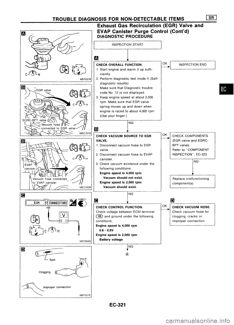
CHECK OVERALL FUNCTION.
~INSPECTION
END
1. Start engine andwarm itup suffi-
ciently.
2. Perform diagnostic testmode II(Self-
diagnostic results).
Make surethatDiagnostic trouble
code No.12isnot displayed.
3. Keep
engine speedatabout 2,000
rpm. Make surethatEGR valve
spring moves upand down when
engine israced toabout 4,000rpm.
(Use yourfinger.)
NG
m
CHECK VACUUM SOURCETOEGR OK
CHECK COMPONENTS
----..
VALVE. (EGR
valve andEGRC-
1. Disconnect vacuumhosetoEGR BPT
valve).
valve. Refer
to"COMPONENT
2. Disconnect
vacuumhosetoEVAP INSPECTION",
EC-323
canister.
3. Check vacuum existence underthe NG
following conditions.
Engine speedis4,000 rpm:
Vacuum shouldnotexist.
Replacemalfunctioning
Engine speedis2,000 rpm:
component(s).
Vacuum shouldexist.
NG
[!J
(!]
CHECK CONTROL FUNCTION. OK
CHECK VACUUM HOSE.
-----.-
Check voltage between ECMterminal Check
vacuum hosefor
@
andground underthefollowing clogging,
cracksor
conditions. improper
connection.
Engine speedis4,000 rpm
0.6 -O.BV
Engine speedis2,000 rpm
Battery voltage
~NG
+
-
MEF637B
MEF955D
TROUBLE
DIAGNOSIS FORNON-DETECTABLE ITEMS
[1[J
Exhaust GasRecirculation (EGR)Valveand
EVAP Canister PurgeControl (Cont'd)
DIAGNOSTIC PROCEDURE
~)5
~~II
EGRC-BPT valve
~~uu~ hose
connected toEGR valve~
(
~
'
MEC761B
Clogging
[!J
r----, ~
CONNECT
II
ECM ~CONNECTORIIl.imJ
£)
105
::::.S.-
~P"P"
'00","'00
MEF521E
EC-321
Page 1041 of 1701
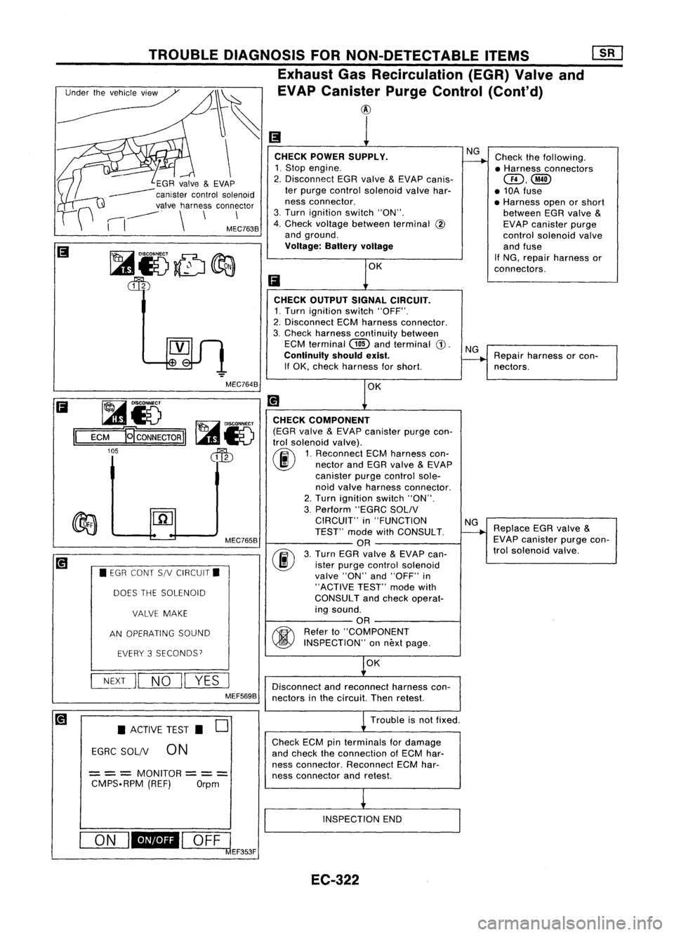
Checkthefollowing.
• Harness connectors
QD,@
• 10A fuse
• Harness openorshort
between EGRvalve
&
EVAP canister purge
control solenoid valve
and fuse
If NG, repair harness or
connectors.
NG
CHECK POWER SUPPLY.
1. Stop engine.
2. Disconnect EGRvalve
&
EVAP canis-
ter purge control solenoid valvehar-
ness connector.
3. Turn ignition switch"ON".
4. Check voltage between terminal
@
and ground.
Voltage: Batteryvoltage
TROUBLE
DIAGNOSIS FORNON-DETECTABLE ITEMS
Exhaust GasRecirculation (EGR)Valveand
_~ ~EVAPcanis:r PurgeControl (Cont'd)
\
~GR valve
&
EVAP
------ canistercontrolsolenoid
valve harness connector
,----,
-----
.
\
\
\
I
I
MEC7638
CHECKOUTPUT SIGNALCIRCUIT.
1. Turn ignition switch"OFF".
2. Disconnect ECMharness connector.
3. Check harness continuity between
ECM terminal
(ill)
andterminal
CD.
Continuity shouldexist.
If OK, check harness forshort.
NG
Repair harness orcon-
nectors.
MEC7648 OK
~i5
1=1
=E=CM=-g CONNECTOR
II
105
MEC7658
• EGR CONT S/VCIRCUIT.
DOES THESOLENOID
VALVE MAKE
AN OPERATING SOUND
EVERY 3SECONDS?
NEXT
II
NO
II
YES
I
MEF5698 CHECK
COMPONENT
(EGR valve
&
EVAP canister purgecon-
trol solenoid valve).
(ij\
1.Reconnect ECMharness con-
~ nectorandEGR valve
&
EVAP
canister purgecontrol sole-
noid valve harness connector.
2. Turn ignition switch"ON".
3. Perform "EGRCSOLIV
CIRCUIT" in"FUNCTION
TEST" modewithCONSULT.
OR
(F./)
3.Turn EGRvalve
&
EVAP can-
~ isterpurge control solenoid
valve "ON"and"OFF" in
"ACTIVE TEST"modewith
CONSULT andcheck operat-
ing sound.
OR
~ Referto"COMPONENT
~ INSPECTION" onnext page.
OK
Disconnect andreconnect harnesscon-
nectors inthe circuit. Thenretest.
NG
Replace EGRvalve
&
EVAP canister purgecon-
trol solenoid valve.
• ACTIVE TEST.
0
EGRC SOL/V
0N
== =
MONITOR
== =
CMPS.RPM (REF)Orpm Trouble
isnot fixed .
Check ECMpinterminals fordamage
and check theconnection ofECM har-
ness connector. ReconnectECMhar-
ness connector andretest.
INSPECTION END
ON
I_I
OFFl
clEF353F
EC-322
Page 1044 of 1701
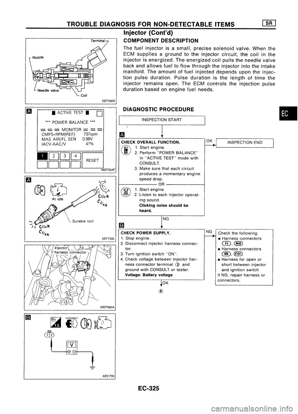
•
INSPECTION END
Check thefollowing.
• Harness connectors
@,@
• Harness connectors
@,
• Harness foropen or
short between injector
and ignition switch
If NG, repair harness or
connectors.
OK
NG
OK
@
INSPECTION
START
DIAGNOSTIC
PROCEDURE
CHECK OVERALL FUNCTION.
(ij\
1.Start engine.
~ 2.Perform "POWER BALANCE"
in "ACTIVE TEST"modewith
CONSULT.
3. Make surethateach circuit
produces amomentary engine
speed drop.
OR
~ 1.Start engine.
~ 2.Listen toeach injector operat-
ing sound.
Clicking noiseshould be
heard.
CHECK POWER SUPPLY.
SEF730L
1.Stop engine.
2. Disconnect injectorharness connec-
tor.
3. Turn ignition switch"ON".
4. Check voltage between injectorhar-
ness connector terminal
@
and
ground withCONSULT ortester.
Voltage: Batteryvoltage
SEF596K
I~~
Click
Ct.
I~-+
TROUBLE
DIAGNOSIS FORNON-DETECTABLE ITEMS
Injector
{Cont'd)
COMPONENT DESCRIPTION
The fuel injector isasmall, precise solenoid valve.Whenthe
ECM supplies aground tothe injector circuit,thecoil inthe
injector isenergized. Theenergized coilpulls theneedle valve
back andallows fueltoflow through theinjector intotheintake
manifold. Theamount offuel injected depends upontheinjec-
tion pulse duration. Pulseduration isthe length oftime the
injector remains open.TheECM controls theinjection pulse
duration basedonengine fuelneeds.
• ACTIVE TEST.
0
••• POWER BALANCE •••
= ==
MONITOR
=
=
=
CMPS.RPM(REF) 737rpm
MAS AIR/FL SENO.98V
IACV-AACjV 41%
110Q]~~
DDDDL:::J
MEF354F
--
/1
MEF960AAEC755 EC-325
Page 1056 of 1701
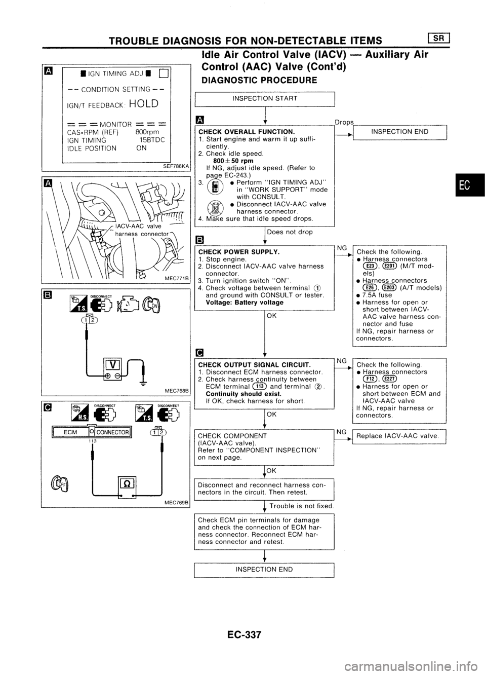
•IGN TIMING ADJ.
0
TROUBLE
DIAGNOSIS FORNON-DETECTABLE ITEMS
[ill
Idle AirControl Valve(IACV) -Auxiliary Air
Control (AAC)Valve(Cont'd)
DIAGNOSTIC PROCEDURE
-- CONDITION SETIING--
IGN/T FEEDBACK HOLD INSPECTION
START
~i5 ~i5
ECM
E[CONNECTORII
cffb
113
=
= =
MONITOR
CAS. RPM (REF)
IGN TIMING
IDLE POSITION
---
---
800rpm
15BTDC
ON
SEF786KA
MEC768B CHECK
OVERALL FUNCTION.
1. Start engine andwarm itup suffi-
ciently.
2. Check idlespeed.
800::1:50
rpm
If NG, adjust idlespeed. (Referto
(l)
e
EC-243.)
3. .. •Perform "IGNTIMING ADJ"
I!I
in"WORK SUPPORT" mode
with CONSULT.
~ •Disconnect IACV-AACvalve
5
harness connector.
4. Ma esure thatidlespeed drops.
Does notdrop
CHECK POWER SUPPLY.
1. Stop engine.
2. Disconnect IACV-AACvalveharness
connector.
3. Turn ignition switch"ON".
4. Check voltage between terminal
G)
and ground withCONSULT ortester.
Voltage: Batteryvoltage
OK
[!1
CHECK OUTPUT SIGNALCIRCUIT.
1. Disconnect ECMharness connector.
2. Check harness continuity between
ECM terminal
CTID
andterminal
(2).
Continuity shouldexist.
If OK, check harness forshort
OK
CHECK COMPONENT
(IACV-AAC valve).
Refer to"COMPONENT INSPECTION"
on next page.
OK Drops
NG
NG
NG INSPECTION
END
Check thefollowing .
• Harness connectors
@D,
([ill)(M/Tmod-
els)
• Harness connectors
@,
@
(A/T
models)
• 7.5A fuse
• Harness foropen or
short between IACV-
AAC valve harness con-
nector andfuse
If NG, repair harness or
con nectors.
Check thefollowing.
• Harness connectors
@,@D
• Harness foropen or
short between ECMand
IACV-AAC valve
If
NG, repair harness or
connectors.
Replace IACV-AAC valve.
•
Disconnect andreconnect harnesscon-
nectors inthe circuit Thenretest
Trouble isnot fixed.
Check ECMpinterminals fordamage
and check theconnection ofECM har-
ness connector. ReconnectECMhar-
ness connector andretest
INSPECTION END
EC-337
Page 1060 of 1701
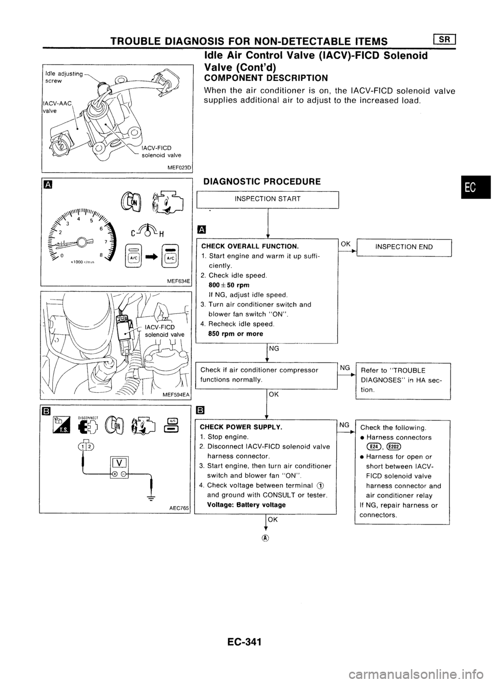
MEF023D
•
Refer to"TROUBLE
DIAGNOSES"
i!1
HA sec-
tion. INSPECTION
END
Check thefollowing.
• Harness connectors
@D,@!)
• Harness foropen or
short between IACV-
FICO solenoid valve
harness connector and
air conditioner relay
If NG, repair harness or
connectors.
OK
NG
NG
CHECK
OVERALL FUNCTION.
1. Start engine andwarm itup suffi-
ciently.
2. Check idlespeed.
800:1::50
rpm
If NG, adjust idlespeed.
3. Turn airconditioner switchand
blower fanswitch "ON".
4. Recheck idlespeed.
850 rpm ormore
Check ifair conditioner compressor
functions normally.
DIAGNOSTIC
PROCEDURE
OKNG
OK
INSPECTION
START
CHECK POWER SUPPLY.
1. Stop engine.
2. Disconnect IACV-FICDsolenoidvalve
harness connector.
3. Start engine, thenturnairconditioner
switch andblower fan"ON".
4. Check voltage between terminal
CD
and ground withCONSULT ortester.
Voltage: Batteryvoltage
AEC765
MEF634E
TROUBLE
DIAGNOSIS FORNON-DETECTABLE ITEMS
[]liJ
Idle AirControl Valve(IACV)-FICD Solenoid
Valve (Cont'd)
COMPONENT DESCRIPTION
When theairconditioner ison, the IACV-FICD solenoidvalve
supplies additional airtoadjust tothe increased load.
Idle
adjusting
screw
EC-341