Page 1087 of 1701
TROUBLEDIAGNOSIS FORNON-DETECTABLE ITEMS~
Torque Converter ClutchSolenoid Valve(Cont'd)
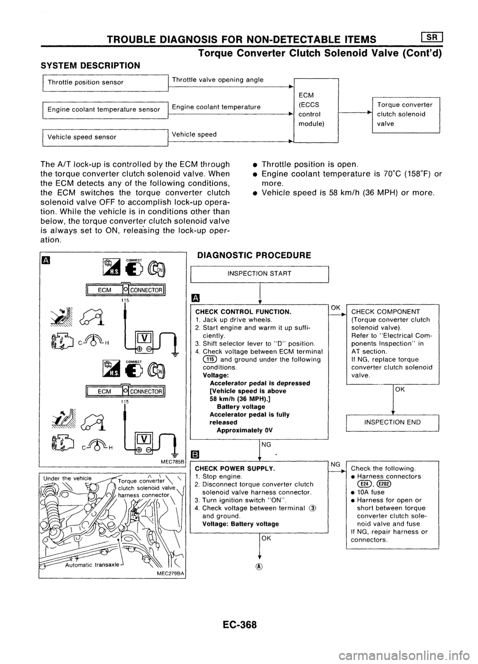
SYSTEM DESCRIPTION
Throttle position sensor Throttle
valveopening angle
Engine coolant temperature sensorEnginecoolant temperature ECM
(ECCS
control
module) Torque
converter
clutch solenoid
valve
Vehicle speedsensor Vehicle
speed
The
AfT
lock-up iscontrolled bythe ECM through
the torque converter clutchsolenoid valve.When
the ECM detects anyofthe following conditions,
the ECM switches thetorque converter clutch
solenoid valveOFFtoaccomplish lock-upopera-
tion. While thevehicle isinconditions otherthan
below, thetorque converter clutchsolenoid valve
is always settoON, relea'sing thelock-up oper-
ation. •
Throttle position isopen .
• Engine coolant temperature is70°C (158°F) or
more .
• Vehicle speedis58 kmfh (36MPH) ormore.
~i3~
II
ECM
E[CONNECTORII
DIAGNOSTIC
PROCEDURE
INSPECTION START
115
OK
INSPECTION END
CHECK
COMPONENT
(Torque converter clutch
solenoid valve).
Refer to"Electrical Com-
ponents Inspection" in
AT section.
If
NG, replace torque
converter clutchsolenoid
valve.
Check thefollowing.
• Harness connectors
@,
• 10A fuse
• Harness foropen or
short between torque
converter clutchsole-
noid valve andfuse
If NG, repair harness or
connectors.
NG
OK
OK
@
CHECK
CONTROL FUNCTION.
1. Jack updrive wheels.
2. Start engine andwarm itup suffi-
ciently.
3. Shift selector leverto"0" position.
4. Check voltage between ECMterminal
GID
andground underthefollowing
conditions.
Voltage: Accelerator pedalIsdepressed
[Vehicle speedisabove
58 km/h (36MPH).]
Battery voltage
Accelerator pedalisfully
released
Approximately OV
CHECK POWER SUPPLY.
1. Stop engine.
2. Disconnect torqueconverter clutch
solenoid valveharness connector.
3. Turn ignition switch"ON".
4. Check voltage between terminal
@
and ground.
Voltage: Batteryvoltage
-
MEC785B
MEC279BA
Ef
CONNECTOR
II
115
II
ECM
~~
ID
cf8~-H
EC-368
Page 1093 of 1701
VE-TYPE INJECTION PUMP
SEF779A
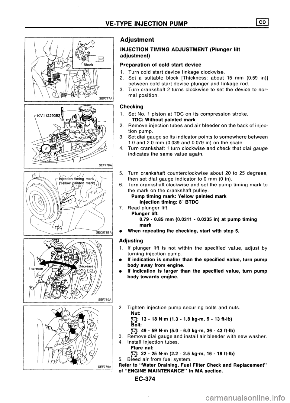
Adjustment
INJECTION TIMINGADJUSTMENT (Plunger
lift
adjustment)
Preparation ofcold start device
1. Turn coldstart device linkage clockwise.
2. Set asuitable block[Thickness: about15mm (0.59 in)]
between coldstart device plunger andlinkage rod.
3. Turn crankshaft 2turns clockwise toset the device tonor-
mal position.
Checking
1. Set NO.1 piston atTDC onitscompression stroke.
TDC: Without paintedmark
2. Remove injection tubesandairbleeder onthe back ofinjec-
tion pump.
3. Set dial gauge soitsindicator pointstosomewhere between
1.0 and 2.0mm (0.039 and0.079 in)onthe scale.
4. Turn crankshaft 1turn clockwise andcheck thatdialgauge
indicates thesame value again.
5. Turn crankshaft counterclockwise about20to25 degrees,
then setdial gauge indicator to0mm (0in).
6. Turn crankshaft clockwiseandsetthe pump timing markto
the mark onthe crankshaft pulley.
Pump timing mark:Yellow painted mark
Injection timing:8
0
BTDC
7. Read plunger lift.
Plunger lift:
0.79 -0.85 mm(0.0311 -0.0335 in)atpump timing
mark
• When repeating thechecking, startwithstep 5.
Adjusting
1. Ifplunger liftisnot within thespecified value,adjust by
turning injection pump.
• Ifindication issmaller thanthespecified value,turnpump
body away fromengine.
• Ifindication islarger thanthespecified value,turnpump
body towards engine.
2. Tighten injection pumpsecuring boltsandnuts.
Nut:
~: 13-18 N.m (1.3-1.8 kg-m, 9-13 ft-Ib)
Bolt:
~: 49-59 N.m (5.0-6.0 kg-m, 36-43 ft-Ib)
3. Remove dialgauge andinstall airbleeder withnewwasher.
4. Install injection tubes.
Flare nut:
~: 22-25 N.m (2.2-2.5 kg-m, 16-18 ft-Ib)
5. Bleed airfrom fuelsystem.
Refer to"Water Draining, FuelFilter Check andReplacement"
of "ENGINE MAINTENANCE" inMA section.
EC-374
Page 1114 of 1701
TROUBLEDIAGNOSES
Quick-glow System(Cont'd)
@
CHECK COMPONENTS NG
(Glow relay, Glowplug,Engine coolant
temperature sensor,Key-inswitch, Igni-
tion switch).
Refer to"Component Inspection"(EC-
397).
OK
Disconnect andreconnect harnesscon-
nectors inthe circuit. Thenretest.
Trouble isnot fixed.
Check ECMpinterminals fordamage or
the connection ofECM harness connec-
tor. Reconnect ECMharness connector
and retest. Replace
malfunctioning
component(s).
•
BATIERY [
Voltage
OV
Ignition
key
START
[
ON
IN [
OUT
,
,
,
I
,
JL
SEC5558SYSTEM
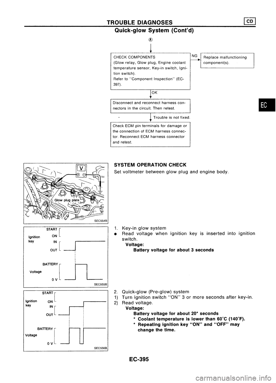
OPERATION CHECK
Set voltmeter betweenglowplugandengine body.
1. Key-in glowsystem
• Read voltage whenignition keyisinserted intoignition
switch.
Voltage: Battery voltage forabout 3seconds
Ignition
key
BATIERY [
Voltage
OV
SEC5568
2.
Quick-glow (Pre-glow)system
1) Turn ignition switch"ON"3or more seconds afterkey-in.
2) Read voltage.
Voltage: Battery voltage forabout 20*seconds
*
Coolant temperature islower than60°C(140°F).
* Repeating ignitionkey"ON" and"OFF" may
change thetime.
EC-395
Page 1115 of 1701
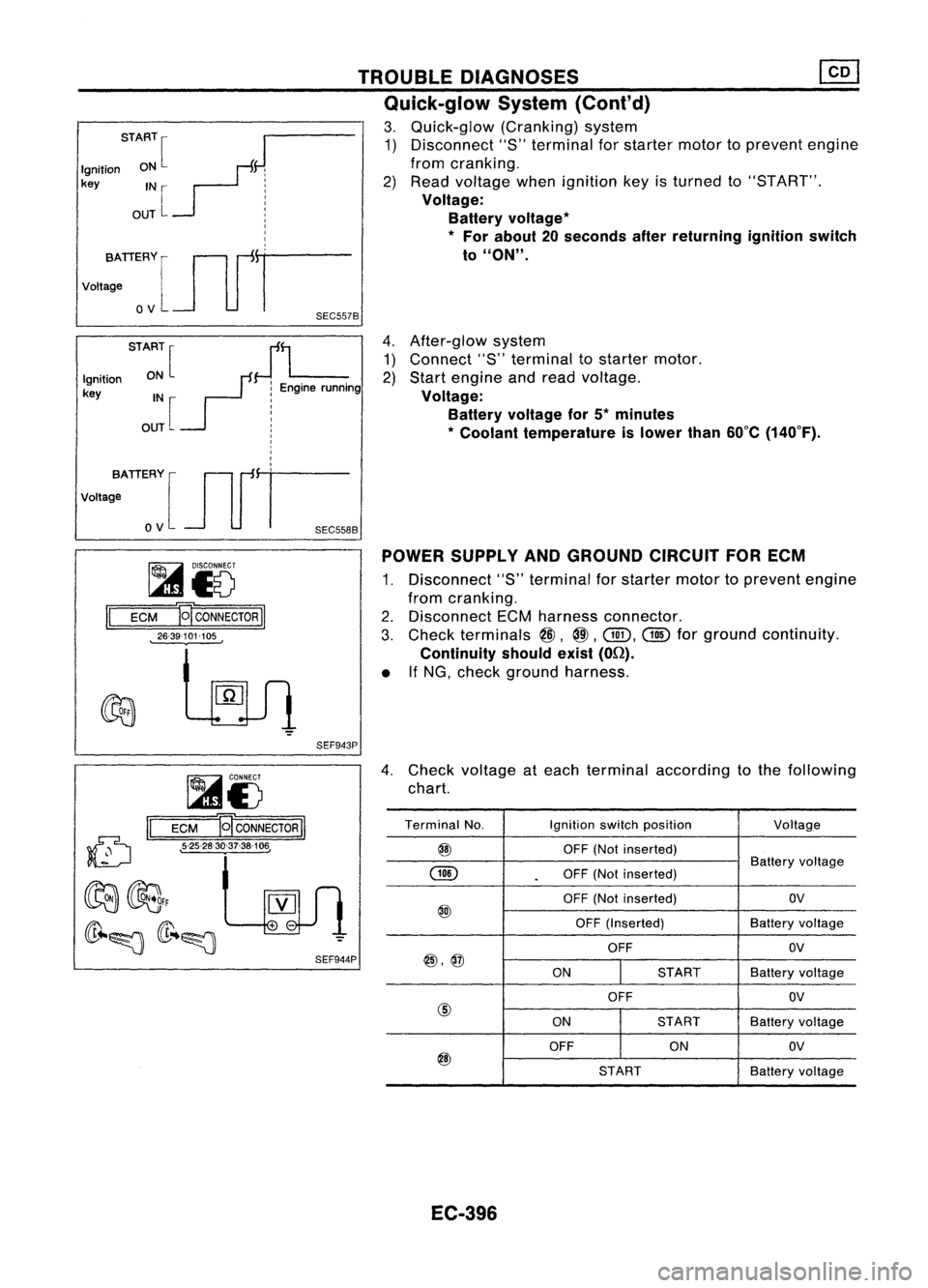
4.After-glow system
1) Connect "8"terminal tostarter motor.
2) Start engine andread voltage.
Voltage: Battery voltage for5*minutes
* Coolant temperature islower than60°C(140°F).
TROUBLE
DIAGNOSES
Quick-glow System(Cont'd)
3. Quick-glow (Cranking)system
1) Disconnect "S"terminal forstarter motortoprevent engine
from cranking.
2) Read voltage whenignition keyisturned to"8T ART".
Voltage: Battery voltage
*
*
For about 20seconds afterreturning ignitionswitch
to
"ON".
START
[
J
Ignition ON
F:
key IN
r- j
OUT
L :
I
I
I
vo,,:TIERYlJlfr
o
V
SEC557B
STA:~[
JL
Ignition
r:
Enginerunning
key IN :
OUT [
!
I
I
,
I
,
votta;ATIERY [Jlfi=
o
V
SEC558B
~i5
II
ECM E
CONNECTOR
II
26-39101-105 POWER
SUPPLY ANDGROUND CIRCUITFORECM
1. Disconnect "S"terminal forstarter motortoprevent engine
from cranking.
2. Disconnect ECMharness connector.
3. Check terminals
@,
@.
Gill.
@
forground continuity.
Continuity shouldexist(On).
• IfNG, check ground harness.
SEF943P
(D
II
~i5
ECM B
CONNECTOR
II
• 5-25-28-30-37-38-106,
4.
Check voltage ateach terminal according tothe following
chart.
Terminal No. Ignitionswitchposition
Voltage
@
OFF(Notinserted)
GID
Battery
voltage
.
OFF
(Notinserted)
OFF (Not inserted) OV
@
OFF(Inserted) Batteryvoltage
OFF OV
@,@
ONSTARTBatteryvoltage
OFF OV
@
ONSTART
Batteryvoltage
OFF ONOV
@
STARTBatteryvoltage
EC-396
Page 1117 of 1701
SEC5658Enginecoolant temperature sensor
Check engine coolant temperature sensorresistance.
Key-in switch
Check continuity betweenterminals ofkey-in switch connector.
11.5
5.6
3.7
1.2
Resistance
kfl
Continuity
No continuity
Continuity shouldexist.
Ignition
key
Not inserted
Inserted
Coolant
temp.°C('F)
-15 (5)
0(32)
10 (50)
40 (104)
TROUBLE
DIAGNOSES
Quick-glow System(Cont'd)
3. Install glowplugconnecting platesecurely.
Connecting
plate
Spring washer
~GIOwnut
Glow harness
Alternator
Refer to"CHARGING SYSTEM"inEL section.
EC-398
Page 1121 of 1701
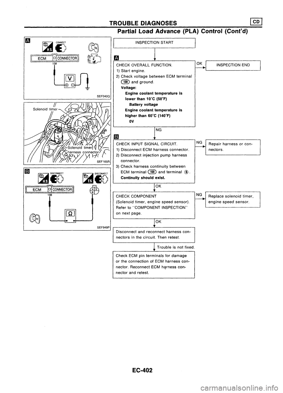
TROUBLEDIAGNOSES ~
Partial LoadAdvance (PLA)Control (Cont'd)
II
~i5
D~CONNECTORII
lOB
~i5
ECM
M
CONNECTOR
II
10B
SEF040Q
SEF949P
INSPECTION
START
CHECK OVERALL FUNCTION.
1) Start engine.
2) Check voltage between ECMterminal
COO
andground.
Voltage: Engine coolant temperature is
lower than10'C (50'F)
Battery voltage
Engine coolant temperature is
higher than60'C (140'F)
OV
CHECK INPUTSIGNAL CIRCUIT.
1) Disconnect ECMharness connector.
2) Disconnect injectionpumpharness
connector.
3) Check harness continuity between
ECM terminal
COO
andterminal
@.
Continuity shouldexist.
OK
CHECK COMPONENT
(Solenoid timer,engine speedsensor).
Refer to"COMPONENT INSPECTION"
on next page.
OK
Disconnect andreconnect harnesscon-
nectors inthe circuit. Thenretest.
Trouble isnot fixed.
Check ECMpin
terminals
fordamage
or the connection ofECM harness con-
nector. Reconnect ECMh~rness con-
nector andretest.
EC-402 OK
NG
NG
INSPECTION
END
Repair harness orcon-
nectors.
Replace solenoid timer,
engine
speedsensor.
Page 1122 of 1701
If
NG, replace powersteering oilpressure switch.
Solenoid
timer
1. Disconnect solenoidtimerharness connector.
2. Apply battery voltage tosolenoid timerterminals andlisten
for operating sound.
•
No
Operating
sound
Yes
Condition
With battery voltage applied
Without batteryvoltage applied
TROUBLE
DIAGNOSES ~
Partial LoadAdvance (PLA)Control (Cont'd)
COMPONENT INSPECTION
Engine speedsensor
1. Disconnect enginespeedsensor harness connector.
2. Check resistance betweenterminals
@
and
CID.
Resistance: Approximately 1.6Q
If
NG, replace fuelpump.
EC-403
Page 1127 of 1701
TROUBLEDIAGNOSES
Cooling FanControl (Cont'd)
Checkcooling fanlow
speed control circuit.
(Go to
I
PROCEDURE C
P
Check cooling fanhigh
speed control circuit.
(Go to
I
PROCEDURE D
I.)
NG
NG
INSPECTION
START
OK
CHECK COOLING FANHIGH SPEED
OPERATION. 1) Turn ignition switch"OFF".
2) Reconnect coolingfanrelay-2 and
cooling fanrelay-3.
3) Turn ignition switch"ON".
4) Make surethatcooling fanoperates
at high speed.
CHECK
COOLING FANLOW SPEED
OPERATION. 1) Turn ignition switch"OFF".
2) Disconnect enginecoolant tempera-
ture sensor connector.
SEF168R
3)Disconnect coolingfanrelays 1,2
and 3.
4) Turn ignition switch"ON".
5) Reconnect coolingfanrelay 1.
6) Make surethatcooling fanoperates
at low speed.
SEC163BA OK
INSPECTION END
EC-408