Page 1203 of 1701
TIMINGCHAIN ~
Installation (Cont'd)
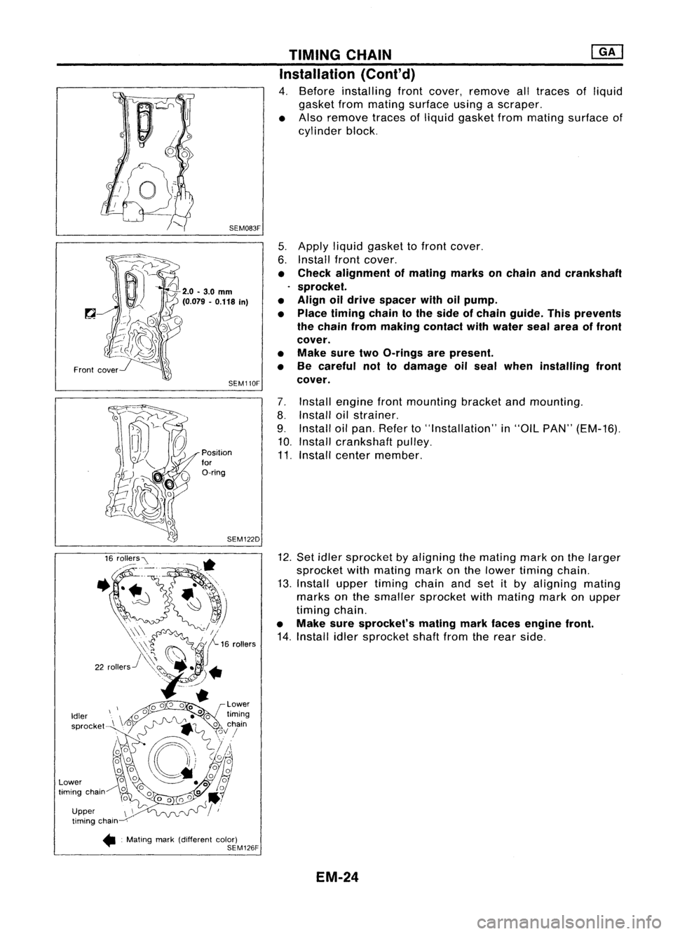
4. Before installing frontcover, remove alltraces ofliquid
gasket frommating surface usingascraper.
• Also remove tracesofliquid gasket frommating surface of
cylinder block.
5. Apply liquidgasket tofront cover.
6. Install frontcover.
• Check alignment ofmating marksonchain andcrankshaft
sprocket.
• Align oildrive spacer withoilpump.
• Place timing chaintothe side ofchain guide. Thisprevents
the chain frommaking contact withwater sealarea offront
cover.
• Make suretwoO-rings arepresent.
• Be careful nottodamage oilseal when installing front
cover.
7. Install engine frontmounting bracketandmounting.
8. Install oilstrainer.
9. Install oilpan. Refer to"Installation" in"OIL PAN" (EM-16).
10. Install crankshaft pulley.
11. Install center member.
12. Set idler sprocket byaligning themating markonthe larger
sprocket withmating markonthe lower timing chain.
13. Install uppertiming chainandsetitby aligning mating
marks onthe smaller sprocket withmating markonupper
timing chain.
• Make suresprocket's matingmarkfaces engine front.
14. Install idlersprocket shaftfromtherear side.
SEM083F
SEM110F
SEM122D
Position
for
O-ring
Front
cover
Upper timing chain
•. Mating mark(different color)
SEM126F
Idler
sprocket
Lower
timing chain
EM-24
Page 1205 of 1701
Intakeside
o~ ~
~NO.5~
~ ~No. 4~
~ "'DNo. 3"~
L
"\J;;\
No.2
~V~NO'
~~FronOt mark~
Front ......., TIMING
CHAIN
Installation (Cont'd)
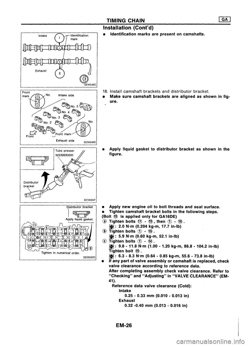
• Identification marksarepresent oncamshafts.
18. Install camshaft bracketsanddistributor bracket.
• Make surecamshaft bracketsarealigned asshown infig-
ure.
Exhaust side
SEM549D
Distributor bracket
I~
Apply liquidgasket.
@
@
@
rl~FL~~I~~~~
),i
o)(oo~-.'.-
0l1..0)(
0
~ .@/~
o'(!l@
@
cID
CD~cID
oc1)
1
0
@
Tighten innumerical order.
SEM550D
•
Apply liquidgasket todistributor bracketasshown inthe
figure.
• Apply newengine oiltobolt threads andseat surface.
• Tighten camshaft bracketboltsinthe following steps.
(Bolt
@>
isapplied onlyforGA16DE)
@
Tighten bolts
@-
@>,
then
CD-
@).
~: 2.0N'm (0.204 kg-m,17.7in-Ib)
@
Tighten bolts
CD-
@>.
~: 5.9N'm (0.60 kg-m, 52.1in-Ib)
@
Tighten bolts
CD-
@.
~: 9.8-11.8 N'm (1.00 -1.20 kg-m, 86.8-104.2 in-Ib)
Tighten bolt
@>.
~: 6.3-8.3 N'm (0.64 -0.85 kg-m, 55.6-73.8 in-Ib)
• Ifany part ofvalve assembly orcamshaft isreplaced, check
valve clearance accordingtoreference data.
After completing assemblycheckvalveclearance. Referto
"Checking" and"Adjusting" in"VALVE CLEARANCE" (EM-
41).
Reference datavalve clearance (Cold):
Intake
0.25 -0.33 mm(0.010 -0.013 in)
Exhaust
0.32 -0.40 mm(0.013 -0.016 in)
EM-26
Page 1206 of 1701
•:Mating mark(different color) 16
rollers
SEM129F TIMING
CHAIN
@K]
Installation
(Cont'd)
19. Assemble camshaftsprocketwithchain.
• Set timing chainbyaligning matingmarkswiththose of
camshaft sprockets.
• Make suresprocket's matingmarksfaceengine front.
20. Install camshaft sprocketbolts.
• Apply newengine oiltobolt threads andseat surface .
•
SEM657D
2.0.3.0
mm
(0.079 -0.118 In)
21.
Install upperchaintensioner.
• Before installing chaintensioner, insertasuitable pininto
pin hole ofchain tensioner.
• After installing chaintensioner, removethepin.
22. Install lowerchaintensioner.
CAUTION:
• Check noproblems occurwhenengine isrotated.
• Make surethatNo.1piston isset atTOC onitscompres-
sion stroke.
• Make sureofthe direction ofthe gasket beforeinstalling
lower chaintensioner.
23. Apply liquidgasket tothermostat housing.
• Use Genuine LiquidGasket orequivalent.
24. Install thermostat housing.
25. Install waterpump pulley.
EM-27
Page 1208 of 1701
WithoutVTC
Engine front
Unit: mm(in)
~(0.39)
~1-J--10 (0.39)
* -\
3 (0.12)
Z~
Liquid
gasket
SEM59BEA TIMING
CHAIN
Installation (Cont'd)
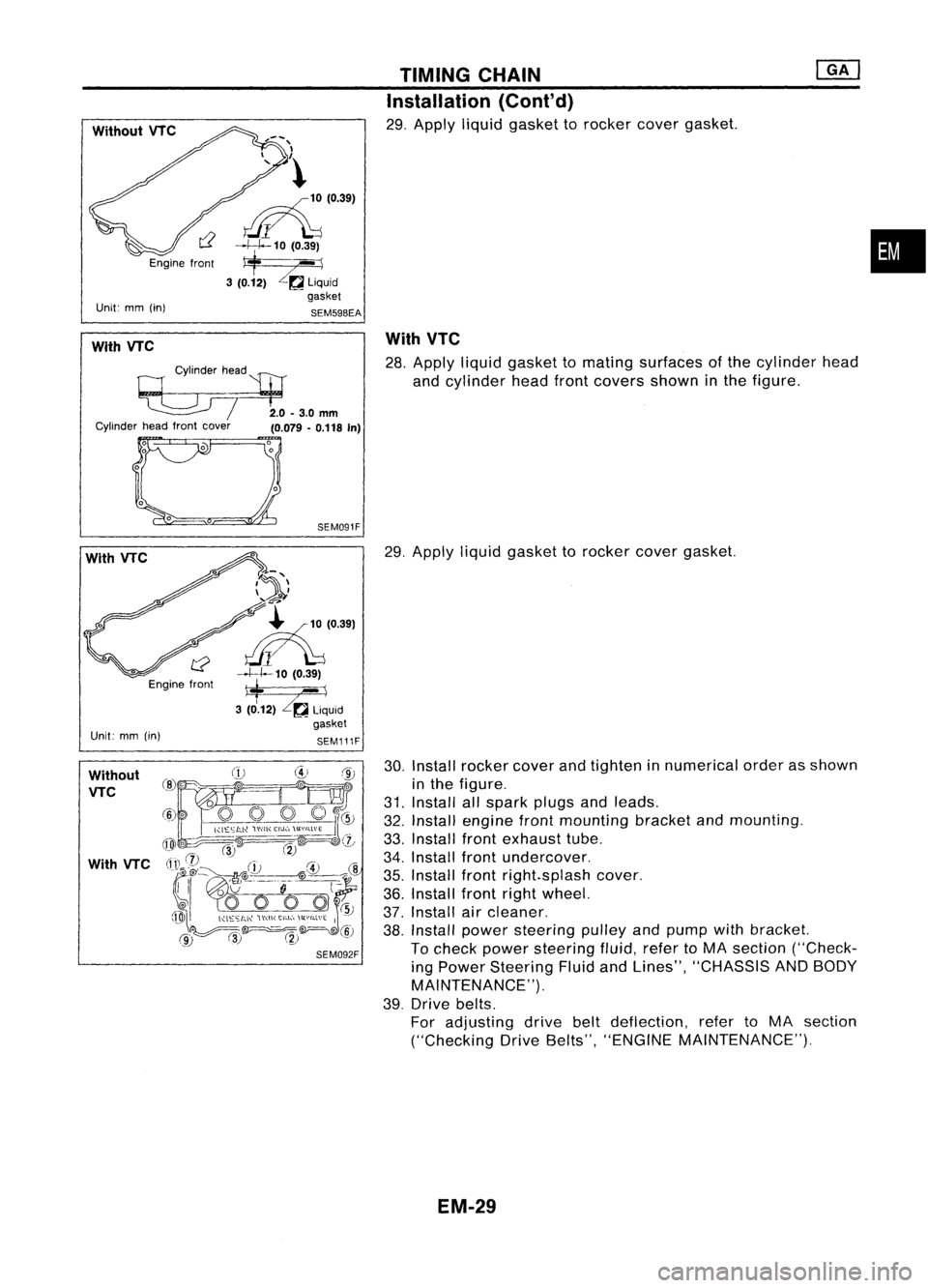
29. Apply liquidgasket torocker covergasket.
•
With VTC
Cylinderhead
'l:tJ
~ /2.0-3.0mm
Cylinder headfront cover
(0.079-0.118 In)
With
VTC
28. Apply liquidgasket tomating surfaces ofthe cylinder head
and cylinder headfrontcovers showninthe figure.
With VTC
Engine front
Unit: mm(in)
SEM091F
7~'\
\ ..... -4'
~-'?
~'0391
~10 (0.39)
*
--1
3 (0.12)
Zr.a
liquid
gasket
SEM111F
29.
Apply liquidgasket torocker covergasket.
Without VTC
With VTC
30.
Install rocker coverandtighten innumerical orderasshown
in the figure.
31. Install allspark plugsandleads.
32. Install engine frontmounting bracketandmounting.
33. Install frontexhaust tube.
34. Install frontundercover.
35. Install frontright.splash cover.
36. Install frontrightwheel.
37. Install aircleaner.
38. Install power steering pulleyandpump withbracket.
To check power steering fluid,refertoMA section ("Check-
ing Power Steering FluidandLines", "CHASSIS ANDBODY
MAINTENANCE").
39. Drive belts.
For adjusting drivebeltdeflection, refertoMA section
("Checking DriveBelts", "ENGINE MAINTENANCE").
EM-29
Page 1213 of 1701
CYLINDERHEAD
CAUTION:
• When installing camshaft, oilseals orother sliding parts,
lubricate contacting surfaceswithnewengine oil.
• When tightening cylinderheadbolts, camshaft sprocket
bolts andcamshaft bracketbolts,lubricate threadportions
and seat surfaces ofbolts withnewengine oil.
• Attach tagstovalve lifters soas not tomix them up.
Removal
• This removal isthe same procedure asthose fortiming
chain. Referto"Removal" in"TIMING CHAIN"(EM-20).
Disassembly
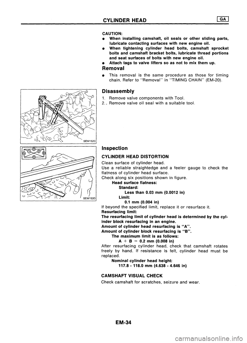
1. Remove valvecomponents withTool.
2 .. Remove valveoilseal withasuitable tool.
Inspection
CYLINDER HEADDISTORTION
Clean surface ofcylinder head.
Use areliable straightedge andafeeler gauge tocheck the
flatness ofcylinder headsurface.
Check alongsixpositions showninfigure.
Head surface flatness:
Standard:
Less than0.03mm(0.0012 in)
Limit: 0.1 mm (0.004 in)
If beyond thespecified limit,replace itor resurface it.
Resurfacing limit:
The resurfacing limitofcylinder headisdetermined bythe cyl-
inder block resurfacing inan engine.
Amount ofcylinder headresurfacing is
"A".
Amount ofcylinder blockresurfacing is
"8".
The maximum limitisas follows:
A +8
=
0.2 mm (0.008 in)
After resurfacing cylinderhead,check thatcamshaft rotates
freely byhand. Ifresistance isfelt, cylinder headmust be
replaced.
Nominal cylinderheadheight:
117.8 -118.0 mm(4.638 .4.646 in)
CAMSHAFT VISUALCHECK
Check camshaft forscratches, seizureandwear.
EM-34
Page 1217 of 1701
I
Recess
1
diameter
I
SEM795A CYLINDER
HEAD
Inspection (Cont'd)
VALVE SEATS
Check valveseats forpitting atcontact surface. Resurface or
replace ifexcessively worn.
• Before repairing valveseats, checkvalveandvalve guide
for wear. Ifthey have worn, replace them.Thencorrect
valve seat.
• Cut with both hands touniform thecutting surface.
REPLACING VALVESEATFORSERVICE PARTS
1. Bore outold seat until
it
collapses. Setmachine depthstop
so that boring cannot contact bottomfaceofseat recess in
cylinder head.
2. Ream cylinder headrecess.
Reaming boreforservice valveseat
Oversize [0.5mm(0.020 in)]:
Unit:mm(in)
Engine model GA16DE
withoutVTC,
GA16DE withVTC
14DE and15DE
30.500 -30.516
Intake (1.2008
-1.2014)
31.500-31.516
31.500 -31.516
(1.2402-1.2408)
(1.2402 -1.2408).
Exhaust 25.500
-25.516
26.500-26.516
(1.0039 -1.0046)
(1.0433-1.0439)
.: GA 16DE without VTC
Use thevalve guide center forreaming toensure valveseatwill
have thecorrect fit.
EM-38
Page 1220 of 1701
VALVECLEARANCE
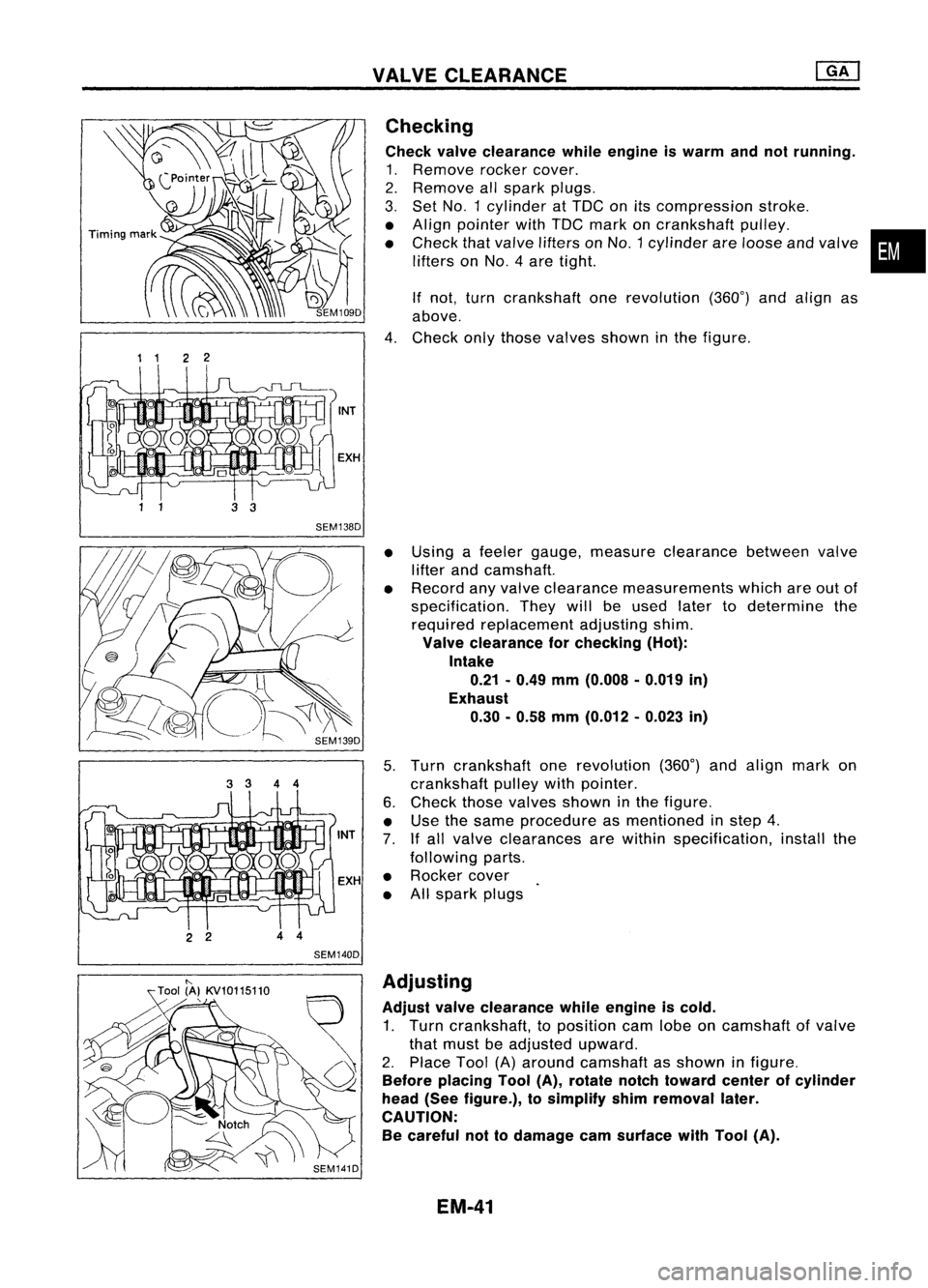
1 1 22
2 2 44
SEM140D Checking
Check valveclearance whileengine iswarm andnotrunning.
1. Remove rockercover.
2. Remove allspark plugs.
3. Set
NO.1
cylinder atTOC onitscompression stroke.
• Align pointer withTOC mark oncrankshaft pulley.
• Check thatvalve lifters on
NO.1
cylinder areloose andvalve
lifters on
NO.4
aretight.
If not, turn crankshaft onerevolution (360°)andalign as
above.
4. Check onlythose valves showninthe figure.
• Using afeeler gauge, measure clearance betweenvalve
lifter andcamshaft.
• Record anyvalve clearance measurements whichareoutof
specification. Theywillbeused latertodetermine the
required replacement adjustingshim.
Valve clearance forchecking (Hot):
Intake 0.21 -0.49 mm(0.008 .0.019 in)
Exhaust 0.30. 0.58mm(0.012 -0.023 in)
5. Turn crankshaft onerevolution (360°)andalign markon
crankshaft pulleywithpointer.
6. Check thosevalves shown inthe figure.
• Use thesame procedure asmentioned instep 4.
7. Ifall valve clearances arewithin specification, installthe
following parts.
• Rocker cover
• Allspark plugs
•
"-
Tool (A}KV10115110
,
SEM141DAdjusting
Adjust valveclearance whileengine iscold.
1. Turn crankshaft, toposition camlobeoncamshaft ofvalve
that must beadjusted upward.
2. Place Tool(A)around camshaft asshown infigure.
Before placing Tool(A),rotate notchtoward centerofcylinder
head (Seefigure.), tosimplify shimremoval later.
CAUTION: Be careful nottodamage camsurface withTool (A).
EM-41
Page 1241 of 1701
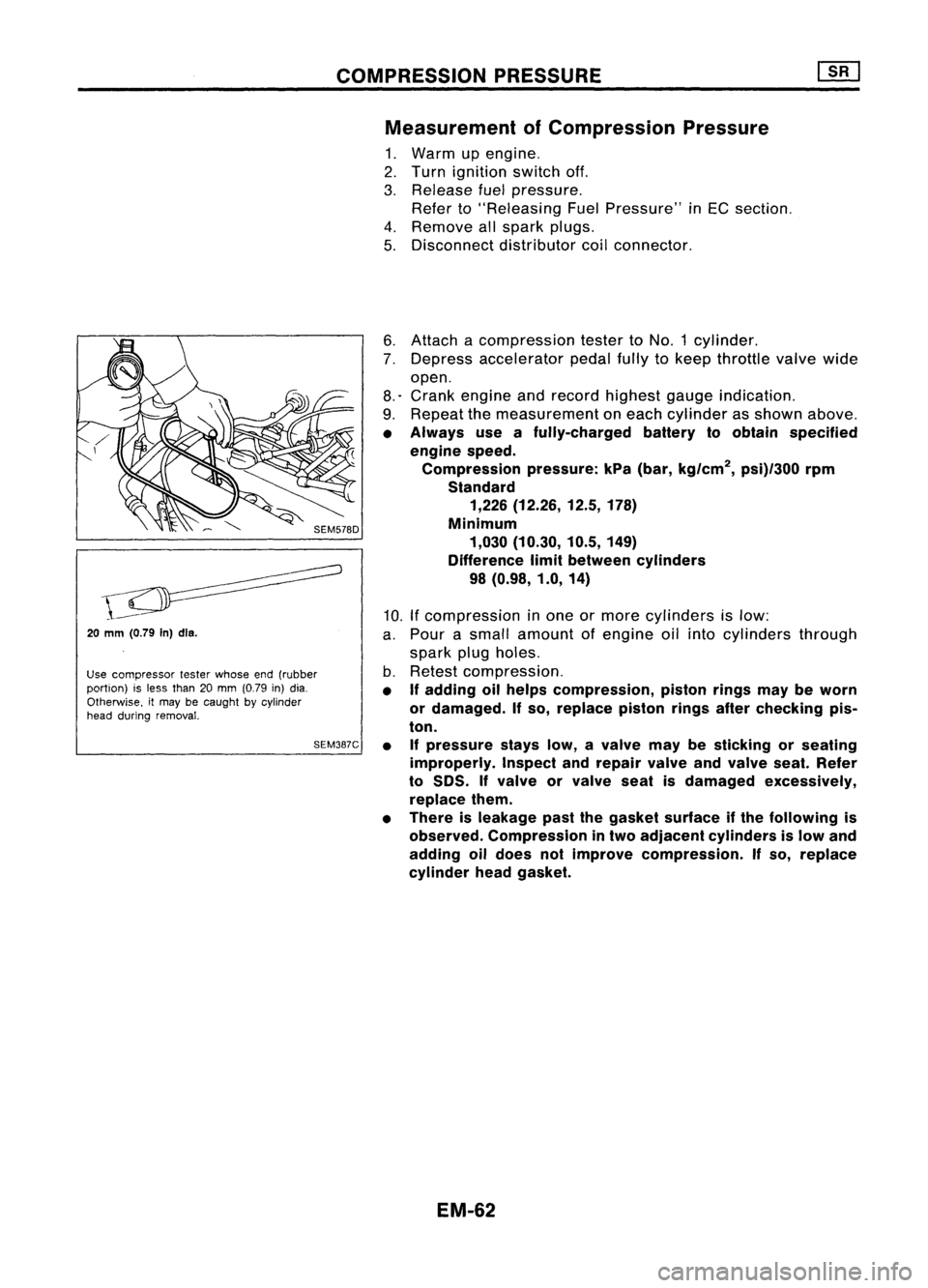
COMPRESSIONPRESSURE
Measurement ofCompression Pressure
1. Warm upengine.
2. Turn ignition switchoff.
3. Release fuelpressure.
Refer to"Releasing FuelPressure" inEC section.
4. Remove allspark plugs.
5. Disconnect distributorcoilconnector.
20
mm (0.79
In)dls.
Use compressor testerwhose end(rubber
portion) isless than 20mm (0.79 in)dia.
Otherwise. itmay becaught bycylinder
head during removal.
SEM387C6.
Attach acompression testertoNO.1 cylinder.
7. Depress accelerator pedalfullytokeep throttle valvewide
open.
8.' Crank engine andrecord highest gaugeindication.
9. Repeat themeasurement oneach cylinder asshown above.
• Always useafully-charged batterytoobtain specified
engine speed.
Compression pressure:kPa(bar, kg/cm
2,
psi)/300 rpm
Standard 1,226 (12.26, 12.5,178)
Minimum 1,030 (10.30, 10.5,149)
Difference limitbetween cylinders
98 (0.98, 1.0,14)
10. Ifcompression inone ormore cylinders islow:
a. Pour asmall amount ofengine oilinto cylinders through
spark plugholes.
b. Retest compression.
• If
adding oilhelps compression, pistonringsmaybeworn
or damaged.
If
so, replace pistonringsafterchecking pis-
ton.
• Ifpressure stayslow,avalve maybesticking orseating
improperly. Inspectandrepair valveandvalve seat.Refer
to
50S.
If
valve orvalve seatisdamaged excessively,
replace them.
• There isleakage pastthegasket surface ifthe following is
observed. Compression intwo adjacent cylinders islow and
adding oildoes notimprove compression.
If
so, replace
cylinder headgasket.
EM-62