1995 NISSAN ALMERA N15 check engine
[x] Cancel search: check enginePage 1335 of 1701
SERVICEDATAANDSPECIFICATIONS (50S)
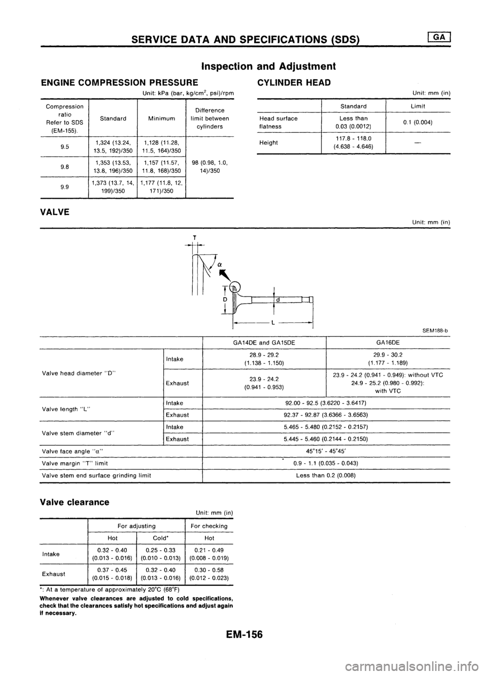
Inspection andAdjustment
ENGINE COMPRESSION PRESSURE CYLINDERHEAD
Unit: kPa(bar, kg/cm
2,
psi)/rpm Unit:
mm(in)
Compression Difference
ratio Standard Minimumlimitbetween
Refer toSDS
cylinders
(EM-155).
9.5 1,324
(13.24, 1,128
(11.28,
13.5, 192)/350 11.5,
164)/350
9.8 1,353
(13.53, 1,157
(11.57,
98(0.98, 1.0,
13.8, 196)/350 11.8,
168)/350
14)/350
9.9 1,373
(13.7,14, 1,177
(11.8,12,
199)/350 171)/350
VALVE
Standard
Limit
Head surface Lessthan
0.1(0.004)
flatness 0.03
(0.0012)
Height 117.8
-118.0
(4.638 -4.646)
-
Unit: mm(in)
---L
SEM188-b
GA14DE andGA15DE GA16DE
Intake 28.9
-29.2 29.9-30.2
(1.138 -1.150) (1.177
-1.189)
Valve headdiameter "0"
23.9-24.2 (0.941 -0.949): without VTC
Exhaust 23.9
-24.2
24.9-25.2 (0.980 -0.992):
(0.941 -0.953)
withVTC
Intake 92.00
-92.5 (3.6220 -3.6417)
Valve length "L"
Exhaust 92.37-92.87 (3.6366 -3.6563)
Intake 5.465-5.480 (0.2152 -0.2157)
Valve stemdiameter "d"
Exhaust 5.445
-5.460 (0.2144 -0.2150)
Valve faceangle "u" 45°15'
-45°45'
.
Valve margin
'T'
limit 0.9-1.1 (0.035 -0.043)
Valve stemendsurface grinding limit Less
than0.2(0.008)
Valve clearance
Unit:mm(in)
For adjusting Forchecking
Hot Cold*
Hot
Intake 0.32
-0.40 0.25
-0.33
0.21-0.49
(0.013 -0.016) (0.010-0.013) (0.008-0.019)
Exhaust 0.37
-0.45 0.32-0.40
0.30-0.58
(0.015 -0.018) (0.013-0.016) (0.012-0.023)
*: At atemperature ofapproximately 20°C(68°F)
Whenever valveclearances areadjusted tocold specifications,
check thattheclearances satisfyhotspecifications andadjust again
if necessary.
EM-156
Page 1355 of 1701
GENERALINFORMATION •
SECTION
G
I
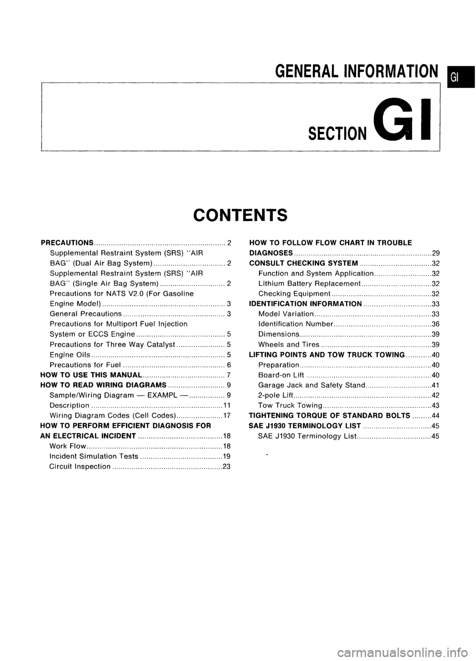
CONTENTS
PRECAUTIONS 2
Supplemental RestraintSystem(SRS)"AIR
BAG" (DualAirBag System) 2
Supplemental RestraintSystem(SRS)"AIR
BAG" (Single AirBag System) 2
Precautions forNATS V2.0(ForGasoline
Engine Model) 3
General Precautions 3
Precautions forMultiport FuelInjection
System orECCS Engine 5
Precautions forThree WayCatalyst 5
Engine Oils 5
Precautions forFuel 6
HOW TOUSE THIS
MANUAL 7
HOW TOREAD WIRING DIAGRAMS 9
Sample/Wiring Diagram-EXAMPL - 9
Description 11
Wiring Diagram Codes(CellCodes) 17
HOW TOPERFORM EFFICIENT DIAGNOSIS FOR
AN ELECTRICAL INCIDENT 18
Work Flow 18
Incident Simulation Tests 19
Circuit Inspection 23
HOW
TOFOLLOW FLOWCHART INTROUBLE
DIAGNOSES 29
CONSULT CHECKING SYSTEM
32
Function andSystem Application 32
Lithium BatteryReplacement.. 32
Checking Equipment 32
IDENTIFICATION INFORMATION 33
Model Variation 33
Identification Number 36
Di mens ions 39
Wheels andTires 39
LIFTING POINTSANDTOW TRUCK TOWING ..40
Preparation 40
Board-on
Lift
40
Garage JackandSafety Stand 41
2-pole Lift 42
Tow Truck Towing 43
TIGHTENING TORQUEOFSTANDARD BOLTS
44
SAE J1930 TERMINOLOGY LIST 45
SAE J1930 Terminology List.. 45
Page 1359 of 1701
PRECAUTIONS
General Precautions (Cont'd)
• After disconnecting vacuumorair hoses, attachatag to
indicate theproper connection.
• Use only thefluids andlubricants specifiedinthis manual.
• Use approved bondingagent,sealants ortheir equivalents
when required.
• Use tools andrecommended specialtoolswhere specified
for safe andefficient servicerepairs.
• When repairing thefuel, oil,water, vacuum orexhaust
systems, checkallaffected linesforleaks.
• Dispose ofdrained oilorthe solvent usedforcleaning parts
in an appropriate manner.
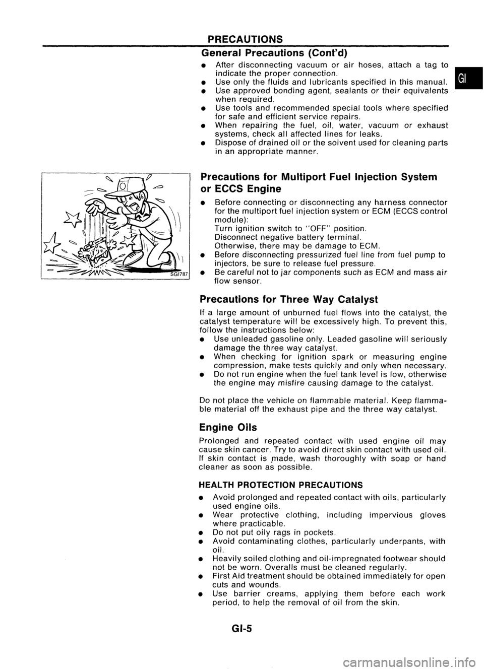
Precautions forMultiport FuelInjection System
or ECCS Engine
• Before connecting ordisconnecting anyharness connector
for the multiport fuelinjection systemorEGM (EGGS control
module):
Turn ignition switchto"OFF" position.
Disconnect negativebatteryterminal.
Otherwise, theremaybedamage toEGM.
• Before disconnecting pressurizedfuellinefrom fuelpump to
injectors, besure torelease fuelpressure.
• Becareful nottojar components suchasEGM andmass air
flow sensor.
Precautions forThree WayCatalyst
If a large amount ofunburned fuelflows intothecatalyst, the
catalyst temperature willbeexcessively high.Toprevent this,
follow theinstructions below:
• Use unleaded gasolineonly.Leaded gasoline willseriously
damage thethree waycatalyst.
• When checking forignition sparkormeasuring engine
compression, maketestsquickly andonly when necessary.
• Donot run engine whenthefuel tank level islow, otherwise
the engine maymisfire causing damage tothe catalyst.
Do not place thevehicle onflammable material.Keepflamma-
ble material offthe exhaust pipeandthethree waycatalyst.
Engine Oils
Prolonged andrepeated contactwithused engine oilmay
cause skincancer. Trytoavoid direct skincontact withused oil.
If skin contact is.made, washthoroughly withsoap orhand
cleaner assoon aspossible.
HEALTH PROTECTION PRECAUTIONS
• Avoid prolonged andrepeated contactwithoils, particularly
used engine oils.
• Wear protective clothing,including impervious gloves
where practicable.
• Donot putoily rags inpockets.
• Avoid contaminating clothes,particularly underpants, with
oil.
• Heavily soiledclothing andoil-impregnated footwearshould
not beworn. Overalls mustbecleaned regularly.
• First Aidtreatment shouldbeobtained immediately foropen
cuts andwounds.
• Use barrier creams, applying thembefore eachwork
period, tohelp theremoval ofoil from theskin.
GI-5
•
Page 1360 of 1701
PRECAUTIONS
Engine Oils(ConI' d)
• Wash withsoap andwater toensure alloil isremoved (skin
cleansers andnailbrushes willhelp). Preparations contain-
ing lanolin replace thenatural skinoilswhich havebeen
removed.
• Donot use gasoline, kerosine, dieselfuel,gasoil,thinners
or solvents forcleaning skin.
• If
skin disorders develop,obtainmedical advicewithout
delay.
• Where practicable, degreasecomponents priortohandling.
• Where thereisarisk ofeye contact, eyeprotection should
be worn, forexample, chemicalgogglesorface shields; in
addition aneye wash facility should beprovided.
ENVIRONMENTAL PROTECTIONPRECAUTIONS
Burning usedengine oilinsmall space heaters orboilers can
be recommended onlyforunits ofapproved design.Theheat-
ing system mustmeettherequirements ofHM Inspectorate of
Pollution forsmall burners ofless than 0.4MW. Ifin doubt check
with theappropriate localauthority and/ormanufacturer ofthe
approved appliance.
Dispose ofused oiland used oilfilters through authorized
waste disposal contractors tolicensed wastedisposal sites,or
to the waste oilreclamation trade.Ifin doubt, contact thelocal
authority foradvice ondisposal facilities.
It is illegal topour used oilontothe ground, downsewers or
drains, orinto water courses.
The regulations concerningthepollution ofthe environment
will vary between regions.
Precautions forFuel
GASOLINE ENGINE:
For Europe
Unleaded gasolineofat least 95octane (RON)
CAUTION: Do not use leaded gasoline. Usingleaded gasoline willdamage
the catalytic converter.
Except Europe
Unleaded gasolineofat least 91octane (RON)
DIESEL ENGINE*:
Diesel fuelofat least 50cetane
If two types ofdiesel fuelareavailable, usesummer or
winter fuelproperly according tothe following temperature
conditions.
• Above -rc(20°F) Summer typediesel fuel.
• Below
-rc
(20°F) Wintertypediesel fuel.
CAUTION:
• Donot use home heating oil,gasoline, orother alternate
fuels inyour diesel engine. Theuseofthose cancause
engine damage.
• Donot use summer fuelattemperature below_7°C(20°F).
The cold temperatures willcause waxtoform inthe fuel. As
a result, itmay prevent theengine fromrunning smoothly.
• Donot add gasoline orother alternate fuelstodiesel fuel.
GI-6
Page 1362 of 1701
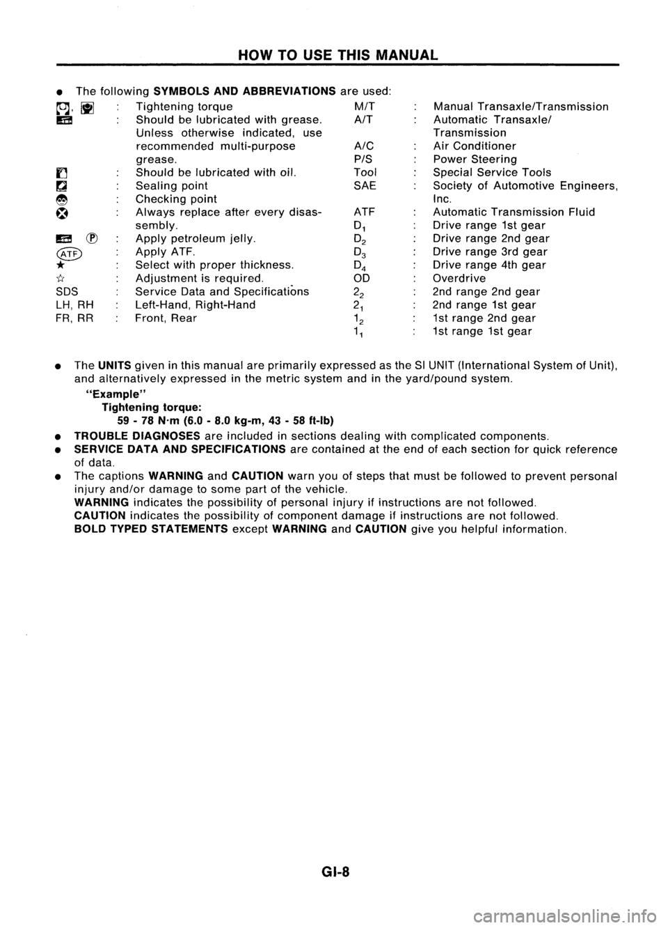
HOWTOUSE THIS MANUAL
ManualTransaxle/Transmission
Automatic Transaxle/
Transmission
Air Conditioner
Power Steering
Special Service Tools
Society ofAutomotive Engineers,
Inc.
Automatic Transmission Fluid
Drive range 1stgear
Drive range 2ndgear
Drive range 3rdgear
Drive range 4thgear
Overdrive
2nd range 2ndgear
2nd range 1stgear
1st range 2ndgear
1st range 1stgear
A/C
PIS
Tool SAE
ATF
0
1
O
2
0
3
0
4
00
2
2
2
1
1
2
1
1
•
The following
SYMBOLS ANDABBREVIATIONS
areused:
to;J,
l\tI
Tightening torque M/T
IE!
Shouldbelubricated withgrease. A/T
Unless otherwise indicated,use
recommended multi-purpose
grease.
Should belubricated withoil.
Sealing point
Checking point
Always replaceafterevery disas-
sembly.
Apply petroleum jelly.
Apply ATF.
Select withproper thickness.
Adjustment isrequired.
Service DataandSpecifications
Left-Hand, Right-Hand
Front, Rear
IE!
~
@
*
1I
SDS LH, RH
FR, RR
• The
UNITS
giveninthis manual areprimarily expressed asthe SlUNIT (International SystemofUnit),
and alternatively expressedinthe metric system andinthe yard/pound system.
"Example" Tightening torque:
59 -78 N'm (6.0-8.0 kg-m, 43-58 ft-Ib)
• TROUBLE DIAGNOSES
areincluded insections dealingwithcomplicated components.
• SERVICE DATAANDSPECIFICATIONS
arecontained atthe end ofeach section forquick reference
of data.
• The captions
WARNING
and
CAUTION
warnyouofsteps thatmust befollowed toprevent personal
injury and/or damage tosome partofthe vehicle.
WARNING
indicatesthepossibility ofpersonal injuryifinstructions arenotfollowed.
CAUTION
indicatesthepossibility ofcomponent damageifinstructions arenotfollowed.
BOLD TYPED STATEMENTS
except
WARNING
and
CAUTION
giveyouhelpful information.
GI-8
Page 1370 of 1701
HOWTOREAD WIRING DIAGRAMS
Description (Cont'd)
FOLDOUT PAGE
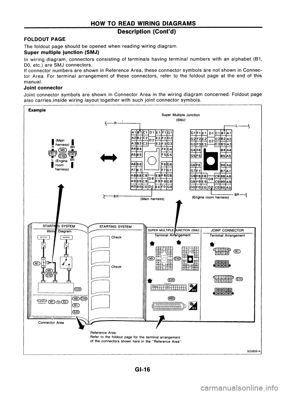
The foldout pageshould beopened whenreading wiringdiagram.
Super multiple junction (SMJ)
In wiring diagram, connectors consistingofterminals havingterminal numbers withanalphabet (81,
DO, etc.) areSMJ connectors.
If connector numbersareshown inReference Area,these connector symbolsarenotshown inConnec-
tor Area. Forterminal arrangement ofthese connectors, refertothe foldout pageatthe end ofthis
manual.
Joint connector
Joint connector symbolsareshown inConnector Areainthe wiring diagram concerned. Foldoutpage
also carries
insidewiring
layouttogether withsuch jointconnector symbols.
Example SuperMultiple Junction
(SMJ)
L----S
I
(Main
I
R harness)
@
BR
1~~_~_5 __
1~1
....... @ID .......
L (Engine BR
I
room
I
harness) AlB1Cl
01ElFIGl
A2B2 C202 E2F2G2
A3B3C3 E3F3G3
A4B4
@]
F4G4
5 B5 F55
A6B6
0
F6G6
A7B7 F77
A8B8C8 E8F8G8
09
A989C9 E9F9G9
AO BOCO DO EOFOGO Gl
FlEl 01ClBlAl
2F2E202C2B2A2
G3 F3E3 C3B3 A3
G4F4
C
B4A4
G5 F5 B5A5
G6 F6 86A6
G7F7 B7A7
G8F8 E8 C888A8
09
G9 F9E9 C989A9
GO FOEO 0 COBO AO
r-
BR
(Mainharness) (Engine
roomharness) BR----{
rDI.TI:IImP
[ill![ill]
@g)
JOINT
CONNECTOR
Terminal Arrangement
*
r::t::rrm::m:J
'M'i'
[ill]II!J ~
*
~
rll"
!! !
I
!
I II
!I
I
'J ~
~lllll!I!!lIllbV ~
SUPER
MULTIPLE UNCTION(SMJ)
Terminal Arangement
*
@)
~=fH+H=1
[II
STARTING
SYSTEM
G
SYSTEM
Diagram
~r-
[Jcheck
CJ
OCh~'
o
[J
STARTI
Wirin
@(3)
'tffB'
@)
Qfu@
@)
@
"-)-~
y
Connector Area
ReferenceArea:
Refer tothe foldout pageforthe terminal arrangement
of the connectors shownhereinthe "Reference Area".
SG1859-A
GI-16
Page 1373 of 1701
HOWTOPERFORM EFFICIENT DIAGNOSIS FORANELECTRICAL INCIDENT
Incident Simulation Tests
INTRODUCTION
Sometimes thesymptom isnot present whenthevehicle isbrought infor service.
If
possible, re-create
the conditions presentatthe time ofthe incident. Doingsomay help avoid aNo Trouble FoundDiag-
nosis. Thefollowing sectionillustrates waystosimulate theconditionslenvironment underwhich the
owner experiences anelectrical incident.
The section isbroken intothesixfollowing topics:
• Vehicle vibration
• Heat sensitive
• Freezing
• Water intrusion
• Electrical load
• Cold orhot start up
Get athorough description ofthe incident fromthecustomer. Itis important forsimulating thecondi-
tions ofthe problem.
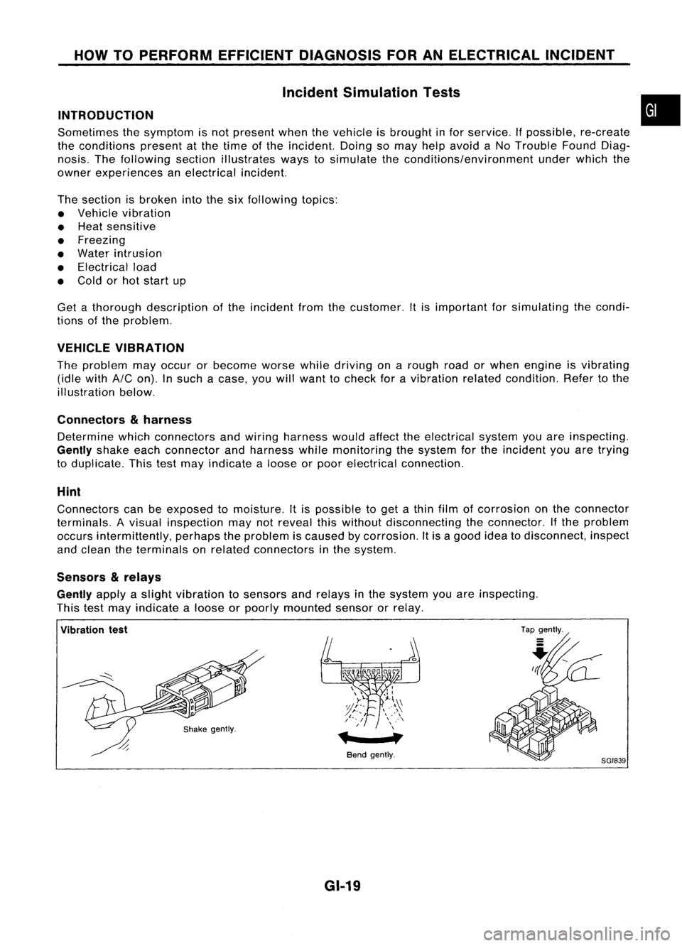
VEHICLE VIBRATION
The problem mayoccur orbecome worsewhiledriving onarough roadorwhen engine isvibrating
(idle with
AIC
on). Insuch acase, youwillwant tocheck foravibration relatedcondition. Refertothe
illustration below.
Connectors
&
harness
Determine whichconnectors andwiring harness wouldaffecttheelectrical systemyouareinspecting.
Gently
shakeeachconnector andharness whilemonitoring thesystem forthe incident youaretrying
to duplicate. Thistestmay indicate aloose orpoor electrical connection.
Hint
Connectors canbeexposed tomoisture. Itis possible toget athin film ofcorrosion onthe connector
terminals. Avisual inspection maynotreveal thiswithout disconnecting theconnector. Ifthe problem
occurs intermittently, perhapstheproblem iscaused bycorrosion. Itis agood ideatodisconnect, inspect
and clean theterminals onrelated connectors inthe system.
Sensors
&
relays
Gently
applyaslight vibration tosensors andrelays inthe system youareinspecting.
This testmay indicate aloose orpoorly mounted sensororrelay.
•
Vibration test
Bendgently.
GI-19
Tap
gently.
8GI839
Page 1375 of 1701
HOWTOPERFORM EFFICIENT DIAGNOSIS FORANELECTRICAL INCIDENT
Incident Simulation Tests(Cont'd)
Engine compartment
There areseveral reasons avehicle orengine vibration could•
cause anelectrical complaint. Someofthe things tocheck for
are:
• Connectors notfully seated.
• Wiring harness notlong enough andisbeing stressed due
to engine vibrations orrocking.
• Wires laying across brackets ormoving components.
• Loose, dirtyorcorroded groundwires.
• Wires routed tooclose tohot components.
To inspect components underthehood, startbyverifying the
integrity ofground connections. (RefertoGROUND INSPEC-
TION described later.)Firstcheck thatthesystem isproperly
grounded. Thencheck forloose connection by
gently shaking
the wiring orcomponents aspreviously explained. Usingthe
wiring diagrams inspectthewiring forcontinuity.
Behind theinstrument panel
An improperly routedorimproperly clampedharnesscan
become pinchedduringaccessory installation. Vehiclevibra-
tion canaggravate aharness whichisrouted alongabracket
or near ascrew.
Under seating areas
An unclamped orloose harness cancause wiring tobe pinched
by seat components (suchasslide guides) duringvehicle vibra-
tion. Ifthe wiring runsunder seating areas,inspect wirerout-
ing forpossible damageorpinching.
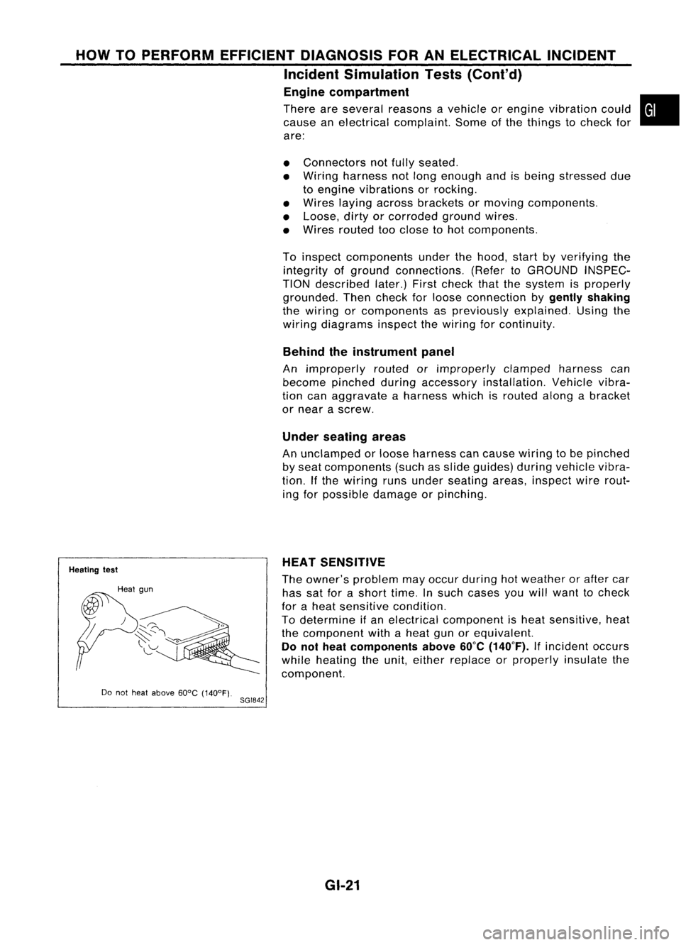
Heating test
Do not heat above 60°C(140°F).
8GI842 HEAT
SENSITIVE
The owner's problem mayoccur during hotweather orafter car
has satforashort time.Insuch cases youwillwant tocheck
for aheat sensitive condition.
To determine ifan electrical component isheat sensitive, heat
the component withaheat gunorequivalent.
Do not heat components above
60°C
(140°F).
Ifincident occurs
while heating theunit, either replace orproperly insulatethe
component.
GI-21