Page 1385 of 1701
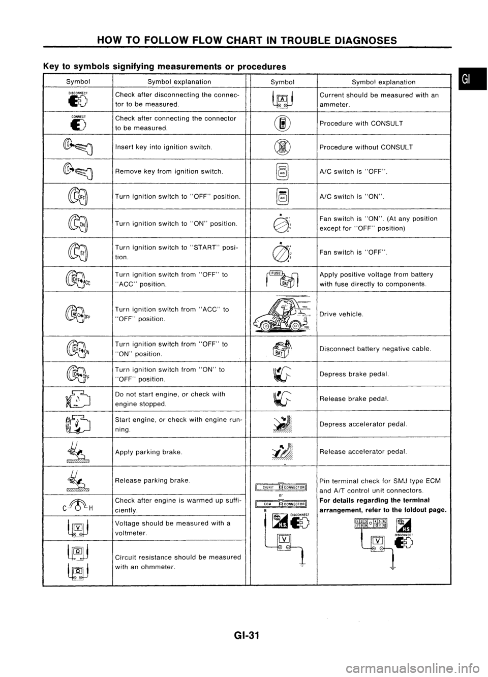
HOWTOFOLLOW FLOWCHART INTROUBLE DIAGNOSES
Key tosymbols signifying measurements orprocedures
Symbol Symbolexplanation
SymbolSymbolexplanation
DISCONNECT
Checkafterdisconnecting theconnec-
~
Current
shouldbemeasured withan
~8
tor
tobe measured.
ammeter.
CONNECT
Checkafterconnecting theconnector
00
E)
tobe measured. Procedure
withCONSULT
(lr~~
Insert
keyinto ignition switCh.
@
Procedure
withoutCONSULT
(lr ..~
Remove
keyfrom ignition switch.
~AIC
switch is"OFF".
~
Turn
ignition switchto"OFF" position.
~AIC
switch is"ON".
~
"
Fanswitch is"ON". (Atany position
Turn ignition switchto"ON" position.
@:;
exceptfor"OFF" position)
~ "
Turn ignition switchto"START" posi-
@'~
Fan
switch is"OFF".
tion.
~~
Turn
ignition switchfrom"OFF" to
~
Apply
positive voltagefrombattery
"ACC" position.
BA;
withfuse directly tocomponents.
~~r
Turn
ignition switchfrom"ACC" to
m-
~'~:
Drive
vehicle.
"OFF" position.
,.-=.
L
@J~ ..
~(e.-
OON
Turn
ignition switchfrom"OFF" to
~~
Disconnect
batterynegative cable.
"ON" position.
BAi
~F
Turn
ignition switchfrom"ON" to
~
Depress
brakepedal.
"OFF" position.
~
Do
not start engine, orcheck with
~
Release
brakepedal.
engine stopped.
ID
Start
engine, orcheck withengine run-
~
ning. Depress
accelerator pedal.
.
.
~
Apply
parking brake.
i!J
Release
accelerator pedal.
..
~
Release
parkingbrake.
~
Pin
terminal checkforSMJ typeECM
and
AIT
control unitconnectors
or
Cff~H
Check
afterengine iswarmed upsuffi-
~ For
details regarding theterminal
ciently.
B
arrangement,refertothe foldout page.
~io
~
Voltage
shouldbemeasured witha
lltlllliR~
t~~~18
voltmeter.
[YJ
lJ9j
.
-
Circuit resistance shouldbemeasured
lfJJ
with
anohmmeter.
~
GI-31
•
Page 1400 of 1701
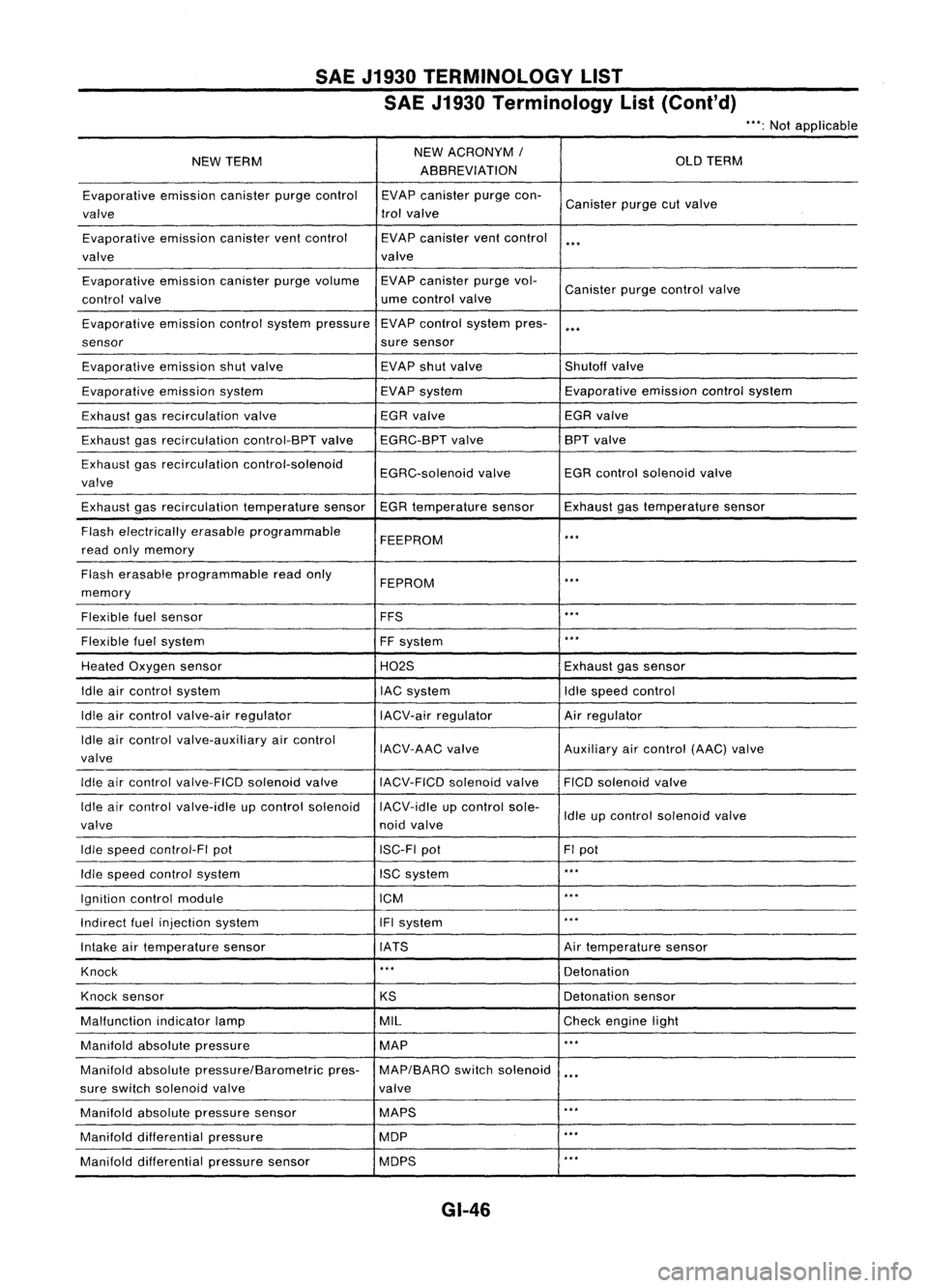
SAEJ1930 TERMINOLOGY LIST
SAE J1930 Terminology List(Cont'd)
***:
Not applicable
NEW TERM NEW
ACRONYM /
OLDTERM
ABBREVIATION
Evaporative emissioncanisterpurgecontrol EVAPcanister purgecon-
Canister purgecutvalve
valve trol
valve
Evaporative emissioncanisterventcontrol EVAPcanister ventcontrol
***
valve valve
Evaporative emissioncanisterpurgevolume EVAPcanister purgevol-
Canister purgecontrol valve
control valve ume
control valve
Evaporative emissioncontrolsystem pressure EVAP
control system pres-
***
sensor suresensor
Evaporative emissionshutvalve EVAP
shutvalve Shutoffvalve
Evaporative emissionsystem EVAPsystem Evaporative
emissioncontrolsystem
Exhaust gasrecirculation valve EGR
valve EGRvalve
Exhaust gasrecirculation control-BPTvalveEGRC-BPT valve BPT
valve
Exhaust gasrecirculation control-solenoid
EGRC-solenoidvalveEGR
control solenoid valve
valve
Exhaust gasrecirculation temperaturesensorEGRtemperature sensorExhaustgastemperature sensor
Flash electrically erasableprogrammable
FEEPROM
***
read onlymemory
Flash erasable programmable readonly
FEPROM
**.
memory
Flexible fuelsensor FFS
***
Flexible fuelsystem
FFsystem
***
Heated Oxygen sensor H02SExhaustgassensor
Idle aircontrol system lACsystem Idlespeed control
Idle aircontrol valve-air regulator IACV-airregulator Airregulator
Idle aircontrol valve-auxiliary aircontrol
IACV-AACvalve Auxiliaryaircontrol (AAC)valve
valve
Idle aircontrol valve-FICO solenoidvalve
IACV-FICDsolenoidvalve FICOsolenoid valve
Idle aircontrol valve-idle upcontrol solenoid IACV-idleupcontrol sole-
Idleupcontrol solenoid valve
valve noidvalve
Idle speed control-FI pot ISC-FIpot FIpot
Idle speed control system ISCsystem
***
Ignition controlmodule ICM
***
Indirect fuelinjection system IFIsystem
***
Intake airtemperature sensor IATS Airtemperature sensor
Knock
***
Detonation
Knock sensor
KSDetonation
sensor
Malfunction indicatorlamp MIL
Checkengine light
Manifold absolutepressure MAP
***
Manifold absolutepressure/Barometric pres-MAP/BARO switchsolenoid
***
sure switch solenoid valve valve
Manifold absolutepressure sensor MAPS
**.
Manifold differential pressure MOP
***
Manifold differential pressuresensor MOPS
***
GI-46
Page 1407 of 1701
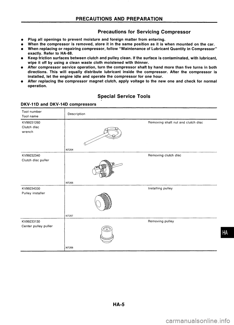
PRECAUTIONSANDPREPARATION
Precautions forServicing Compressor
• Plug allopenings toprevent moisture andforeign matterfromentering.
• When thecompressor isremoved, storeitin the same position asitis when mounted onthe car.
• When replacing orrepairing compressor, follow"Maintenance ofLubricant QuantityinCompressor"
exactly. RefertoHA-68.
• Keep friction surfaces betweenclutchandpulley clean.
If
the surface iscontaminated, withlubricant,
wipe itoff byusing aclean waste clothmoistened withthinner.
• After compressor serviceoperation, turnthecompressor shaftbyhand more thanfiveturns inboth
directions. Thiswillequally distribute lubricantinsidethecompressor. Afterthecompressor is
installed, letthe engine idleandoperate thecompressor forone hour.
• After replacing thecompressor magnetclutch,applyvoltage tothe new oneandcheck fornormal
operation.
SpecialService Tools
DKV-11D andDKV-14D compressors
Tool number
Tool name
KV99231260
Clutch disc
wrench
KV99232340
Clutch discpuller Description
NT204
Removing
shaftnutand clutch disc
Removing clutchdisc
NT206
KV99234330
Installing
pulley
PUlley installer
~
NT207
KV99233130
Removing
pulley
Center pulleypuller
C
•
NT208
HA-5
Page 1416 of 1701
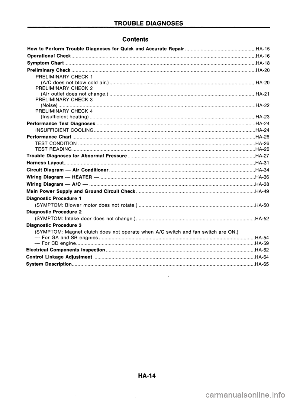
TROUBLEDIAGNOSES
Contents
How toPerform TroubleDiagnoses forQuick andAccurate Repair HA-15
Operational Check HA-16
Symptom Chart HA-18
Preliminary Check HA-20
PRELIMINARY CHECK1
(A/C
does notblow coldair.) HA-20
PRELIMINARY CHECK2
(Air outlet doesnotchange.) HA-21
PRELIMINARY CHECK3
(Noise) HA-22
PRELIMINARY CHECK4
(I nsufficient heating) HA-23
Performance TestDiagnoses HA-24
INSUFFICIENT COOLING HA-24
Performance Chart HA-26
TEST CONDITION HA-26
TEST READING HA-26
Trouble Diagnoses forAbnormal Pressure HA-27
Harness Layout. HA-31
Circuit Diagram -Air Conditioner HA-34
Wiring Diagram -HEATER - HA-36
Wiring Diagram -AIC - HA-38
Main Power Supply andGround CircuitCheck HA-49
Diagnostic Procedure1
(SYMPTOM: Blowermotordoesnotrotate.) HA-50
Diagnostic Procedure2
(SYMPTOM: Intake doordoes notchange.) HA-52
Diagnostic Procedure3
(SYMPTOM: Magnetclutchdoesnotoperate when
A/C
switch andfanswitch areON.)
- For GAand SRengines HA-54
- For CDengine HA-59
Electrical Components Inspection HA-62
Control Linkage Adjustment HA-64
System Description HA-65
HA-14
Page 1418 of 1701
TROUBLEDIAGNOSES
Operational Check
The purpose ofthe operational checkisto confirm thatthesys-
tem operates asitshould. Thesystems whicharechecked are
the blower, mode(discharge air),intake air,temperature
decrease, temperature increase.
CONDITIONS:
Engine running atnormal operating temperature.
RHA315F
RHA316F
Discharge airflow
Switch Airoutlet/distribution
model RHDmodels
LHDmodels
indicator FaceFootDefroster FaceFoot
Defroster
_e
100% 100%
II
-
- -
-
"#Ie
60%
40%
-
60%
40%
-
"J
-
80%
20%14%
65% 21%
,,
-
60% 40%
13%57%
30%
W
-
-
100%
-
-
100%
RHA317F PROCEDURE:
1. Check blower
1) Turn fancontrol knobto1-speed.
Blower shouldoperate on1-speed.
2) Then turnfancontrol knobto2-speed.
3) Continue checking blowerspeeduntilallfour speeds are
checked.
4) Leave blower on4-speed.
2. Check discharge air.
1) Turn mode control knob.
2) Confirm thatdischarge aircomes outaccording tothe air
distribution tableatleft.
Refer to"Discharge AirFlow" in"DESCRIPTION" (HA-12).
HA-16
Page 1422 of 1701
TROUBLEDIAGNOSES
Preliminary Check
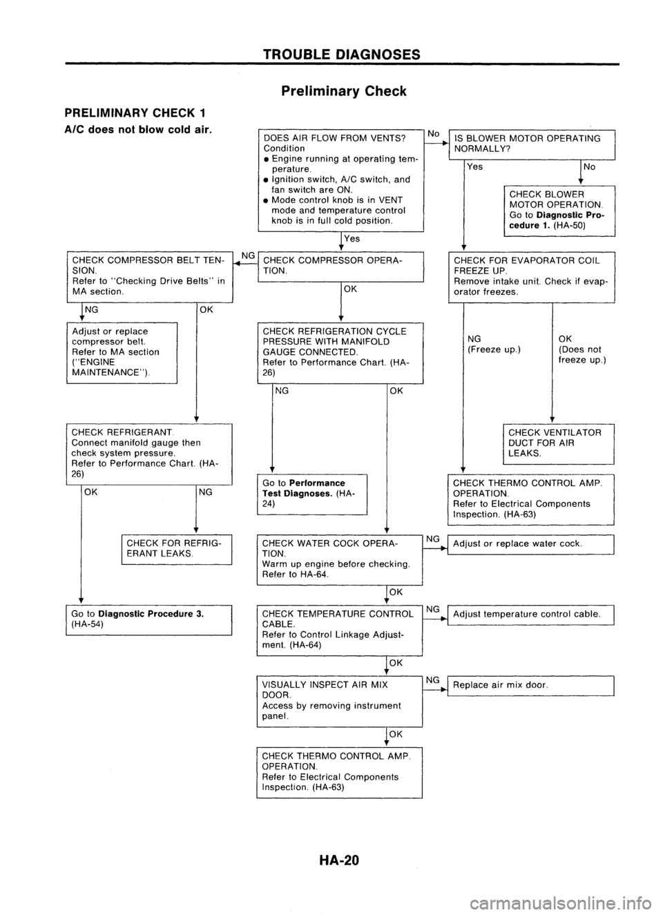
PRELIMINARY CHECK1
Ale
does notblow coldair.
DOESAIRFLOW FROM VENTS?
Condition
• Engine running atoperating tem-
perature .
• Ignition switch,AICswitch, and
fan switch areON.
• Mode control knobisin VENT
mode andtemperature control
knob isinfull cold position.
Yes IS
BLOWER MOTOROPERATING
NORMALLY?
Yes
CHECKBLOWER
MOTOR OPERATION.
Go toDiagnostic Pro-
cedure 1.(HA-50)
CHECK COMPRESSOR BELTTEN-
SION. Refer to"Checking DriveBelts" in
MA section.
CHECK REFRIGERANT.
Connect manifold gaugethen
check system pressure.
Refer toPerformance Chart.(HA-
26)
NG CHECK
THERMO CONTROL AMP.
OPERATION.
Refer toElectrical Components
Inspection. (HA-63)
CHECK
FOREVAPORATOR COIL
FREEZE UP.
Remove intakeunit.Check ifevap-
orator freezes.
NG OK
(Freeze up.) (Doesnot
freeze up.)
CHECK VENTILATOR
DUCT FORAIR
LEAKS.
OK
Go toPerformance
Test Diagnoses. (HA-
24)
NG
CHECK
REFRIGERATION CYCLE
PRESSURE WITHMANIFOLD
GAUGE CONNECTED.
Refer toPerformance Chart.(HA-
26) OK
CHECK
COMPRESSOR OPERA-
TION.
OK
OK NG
Adjust orreplace
compressor belt.
Refer toMA section
("ENGINE
MAINTENANCE").
CHECKFORREFRIG-
ERANT LEAKS CHECK
WATER COCKOPERA-
TION.
Warm upengine beforechecking.
Refer toHA-64.
NG
Adjust orreplace watercock.
OK
Go toDiagnostic Procedure3.
(HA-54) CHECK
TEMPERATURE CONTROL
CABLE.
Refer toControl Linkage Adjust-
ment. (HA-64) NG
Adjust temperature controlcable.
OK
VISUALLY INSPECTAIRMIX
DOOR.
Access byremoving instrument
panel. NG
Replace airmix door.
OK
CHECK THERMO CONTROL AMP.
OPERATION. Refer toElectrical Components
Inspection. (HA-63)
HA-20
Page 1424 of 1701
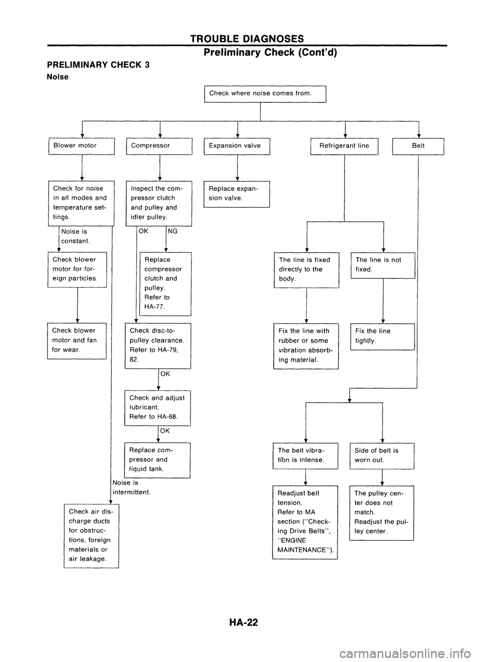
PRELIMINARY CHECK3
Noise TROUBLE
DIAGNOSES
Preliminary Check(Coni'd)
Check wherenoisecomes from.
I
I
Blower motor
Check fornoise
in all modes and
temperature set-
tings.
I
Compressor
Inspect thecom-
pressor clutch
and pulley and
idler pulley. Expansion
valve
Replace expan-
sion valve.
I
Refrigerant line
II
Belt
I
Noise is
constant.
OK
NG
Check blower
motor forfor-
eign particles.
Check blower
motor andfan
for wear. Replace
compressor
clutch and
pulley.
Refer to
HA-77.
Check disc-to-
pulley clearance.
Refer toHA-79,
82.
OK
Check andadjust
lubricant.
Refer toHA-68.
OK
Replace com-
pressor and
liquid tank. The
lineisfixed
directly tothe
body.
Fix the line with
rubber orsome
vibration absorb-
ing material.
The beltvibra-
tion isintense. The
lineisnot
fixed.
Fix the line
tightly.
Side ofbelt is
worn out.
Noise is
i nterm ittent.
Check airdis-
charge ducts
for obstruc-
tions, foreign
materials or
air leakage.
HA-22
Readjust
belt
tension.
Refer toMA
section ("Check-
ing Drive Belts",
"ENGINE
MAINTENANCE"). The
pulley cen-
ter does not
match.
Readjust thepul-
ley center.
Page 1425 of 1701
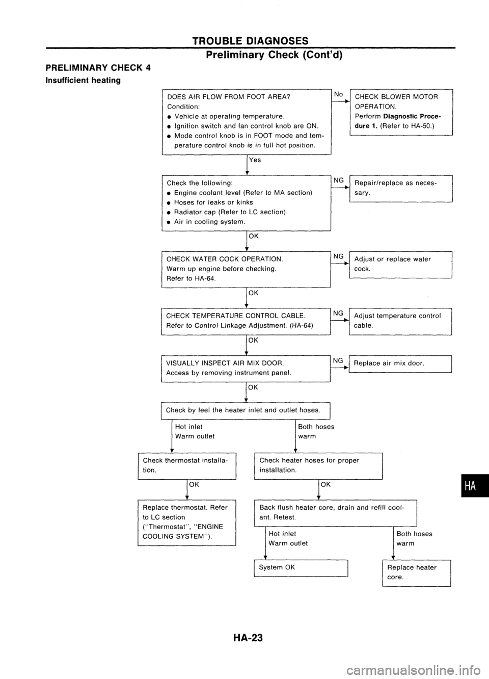
PRELIMINARY CHECK4
Insufficient heating TROUBLE
DIAGNOSES
Preliminary Check(Cont'd)
DOES AIRFLOW FROM FOOTAREA?
Condition:
• Vehicle atoperating temperature .
• Ignition switchandfancontrol knobareON.
• Mode control knobisin FOOT modeandtem-
perature controlknobisinfull hotposition.
Check thefollowing:
• Engine coolant level(Refer toMA section)
• Hoses forleaks orkinks
• Radiator cap(Refer toLC section)
• Air incooling system.
CHECK WATER COCKOPERATION.
Warm upengine before
checking.
Refer toHA-64.
OK
CHECK TEMPERATURE CONTROLCABLE.
Refer toControl Linkage Adjustment. (HA-64)
VISUALLY INSPECTAIRMIX DOOR.
Access byremoving instrument panel.
OK
Check byfeel theheater inletandoutlet hoses.
No
NG
NG
NG
NG
CHECK
BLOWER MOTOR
OPERATION.
Perform
Diagnostic Proce-
dure 1.
(Refer toHA-50.)
Repair/replace asneces-
sary .
Adjust orreplace water
cock.
Adjust temperature control
cable.
Replace airmix door.
Hot inlet
Warm outlet
Check thermostat installa-
tion.
OK
Both
hoses
warm
Check heater hosesforproper
installation.
OK
•
Back
flush heater core,drain andrefill cool-
ant. Retest.
Replace
thermostat. Refer
to LC section
("Thermostat", "ENGINE
COOLING SYSTEM"). Hot
inlet
Warm outlet
System OK
HA-23
Both
hoses
warm
Replace heater
core.