1995 NISSAN ALMERA N15 check engine
[x] Cancel search: check enginePage 1429 of 1701
TROUBLEDIAGNOSES
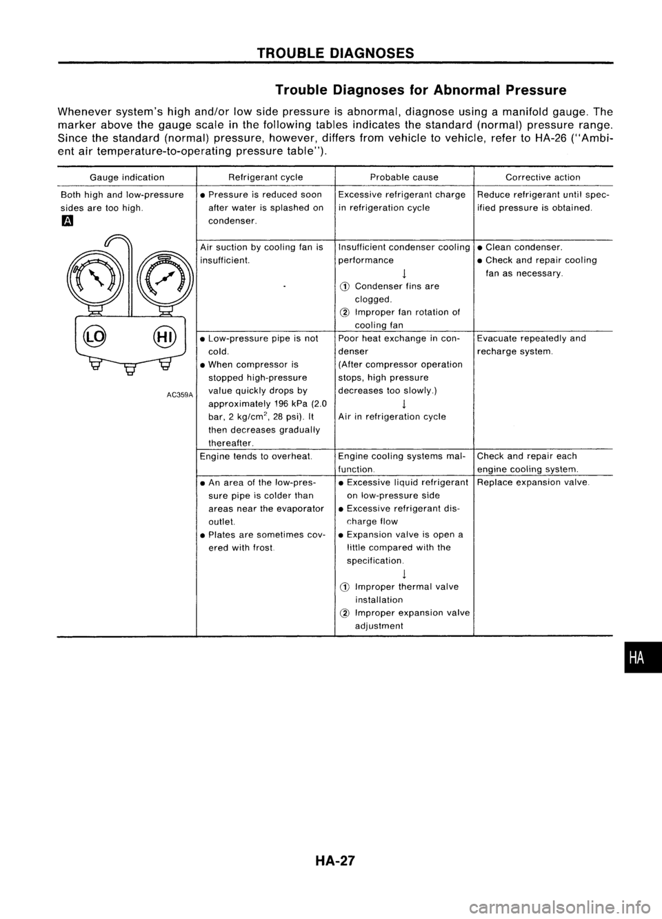
Trouble Diagnoses forAbnormal Pressure
Whenever system'shighand/or lowside pressure isabnormal, diagnoseusingamanifold gauge.The
marker abovethegauge scale
in
the following tablesindicates thestandard (normal)pressure range.
Since thestandard (normal)pressure, however,differsfromvehicle tovehicle, refertoHA-26 ("Ambi-
ent airtemperature-to-operating pressuretable").
Gauge indication
Both highandlow-pressure
sides aretoohigh.
m
Refrigerant
cycle
• Pressure isreduced soon
after water issplashed on
condenser. Probable
cause
Excessive refrigerant charge
in refrigeration cycle Corrective
action
Reduce refrigerant untilspec-
ified pressure isobtained.
•
Check
andrepair each
engine cooling system.
Replace expansion valve.
Evacuate
repeatedly and
recharge system.
Insufficient
condensercooling•Clean condenser.
performance •Check andrepair cooling
!
fanasnecessary.
CD
Condenser finsare
clogged.
@
Improper fanrotation of
cooling fan
Poor heatexchange incon-
denser (After compressor operation
stops, highpressure
decreases tooslowly.)
1
Air inrefrigeration cycle
Engine cooling systems mal-
function. • Excessive liquidrefrigerant
on low-pressure side
• Excessive refrigerant dis-
charge flow
• Expansion valveisopen a
little compared withthe
specification.
1
CD
Improper thermalvalve
installation
@
Improper expansion valve
adjustment
Air
suction bycooling fanis
insufficient.
• An area ofthe low-pres-
sure pipeiscolder than
areas neartheevaporator
outlet.
• Plates aresometimes cov-
ered withfrost.
•
Low-pressure pipeisnot
cold.
• When compressor is
stopped high-pressure
value quickly dropsby
approximately 196kPa (2.0
bar, 2
kg/cm
2,
28psi). It
then decreases gradually
thereafter.
Engine tendstooverheat.
AC359A
HA-27
Page 1456 of 1701
TROUBLEDIAGNOSES
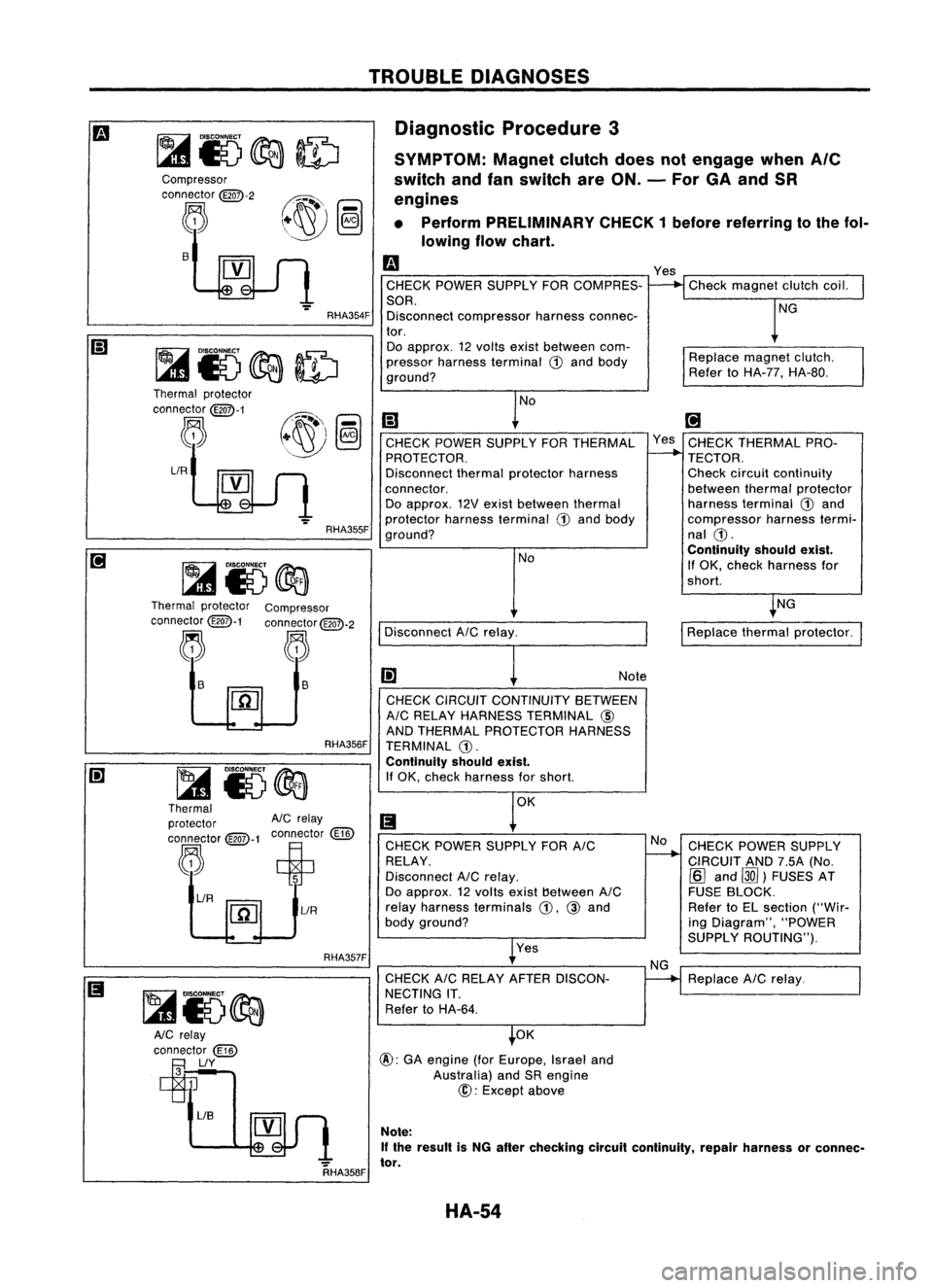
Diagnostic Procedure3
SYMPTOM: Magnetclutchdoesnotengage when
Ale
switch andfanswitch areON. -For GAand SR
engines
• Perform PRELIMINARY CHECK1before referring tothe fol-
lowing flowchart.
Replacemagnetclutch.
Refer toHA-77, HA-80.
Check
magnet clutchcoil.
NG
Yes
m
CHECK POWER SUPPLY FORCOMPRES-
SOR. Disconnect compressor harnessconnec-
tor. Do approx. 12volts existbetween com-
pressor harness terminal
ill
and body
ground?
RHA354F
s
Compressor
connector
@QD-2
~
RHA357FRHA356F
NG
CHECK POWER SUPPLY
CIRCUIT AND7.5A(No.
[Q]
and ~)FUSES AT
FUSE BLOCK.
Refer toEL section ("Wir-
ing Diagram", "POWER
SUPPLY ROUTING").
Replace AICrelay.
I
Replace thermalprotector.
[;J
Yes CHECK THERMAL PRO-
TECTOR.
Check circuit continuity
between thermalprotector
harness terminal
ill
and
compressor harnesstermi-
nal
ill.
Continuity shouldexist.
If OK, check harness for
shorl.
No
NG
CHECK
CIRCUIT CONTINUITY BETWEEN
AIC RELAY HARNESS TERMINAL @
AND THERMAL PROTECTOR HARNESS
TERMINAL
ill.
Continuity shouldexist.
If OK, check harness forshorl. Note
Yes
CHECK
POWER SUPPLY FORAIC
RELAY.
Disconnect AICrelay.
Do approx. 12volts exist!)etween AIC
relay harness terminals
ill,
@
and
body ground?
CHECK AICRELAY AFTER DISCON-
NECTING IT.
Refer toHA-64.
Disconnect
AICrelay. NoNo
[;)
CHECK POWER SUPPLY FORTHERMAL
PROTECTOR.
Disconnect thermalprotector harness
connector. Do approx. 12Vexist between thermal
protector harnessterminal
ill
and body
ground?
OK
@:
GAengine (forEurope, Israeland
Australia) andSRengine
@:
Except above
RHA355F
~ i5@a
Thermal protector
AIC
relay
connector
@-1
connector
(ill)
,"R~~t
[1[]
lIR
lIR
Thermal
protector
connector
@QD-1
~
Thermal protector Compressor
connector
@QD-1
connector
@QD-2
~ ~
~ ~ ls
~
~15~
AlC relay
connector
(ill)
~lIY
RHA358FNote:
If the result isNG after checking circuitcontinuity, repairharness orconnec-
tor.
HA-54
Page 1457 of 1701
•
Replace
dual-pressure
switch.
Note:
If
the result isNG after
checking circuitcontinuity,
repair harness orconnector.
NG
Note
Note
OK
OK
CHECK DUAL-PRESSURE SWITCH.
Refer toHA-64.
Disconnect thermocontrolamp.har-
ness connector.
CHECK
CIRCUIT CONTINUITY
BETWEEN ECM(ECCS CONTROL MOD.
ULE) HARNESS TERMINAL
@
or
@
AND DUAL-PRESSURE SWITCHHAR-
NESS TERMINAL @.
Continuity shouldexist.
If OK, check harness forshort.
OK
@ (Go to
m .)
Disconnect
ECM(ECCS contraImodule)
harness connector.
Disconnect dual-pressure switchhar-
ness connector.
CHECK CIRCUIT CONTINUITY BETWEEN
DUAL.PRESSURE SWITCHHARNESS
TERMINAL @AND THERMO CONTROL
AMP. HARNESS TERMINAL
@.
Continuity shouldexist.
If OK, check harness forshort.
Reconnect dual-pressure switchharness
connector.
o
CHECK
COILSIDECIRCUIT OFAIC No
Disconnect A/Crelay.
~
RELAY. Disconnect
ECM(ECCS
Do approx. 12volts exist between ECM control
module) harness
(ECCS control module) harnessterminal connector.
@
or@ and body ground?
l
Yes
~Note
CHECK CIRCUIT CONTI-
NUITY BETWEEN AIC
RELAY HARNESS TERMI-
NAL @AND ECM (ECCS
CONTROL MODULE)HAR-
.
NESSTERMINAL
@
or
@.
Continuity shouldexist.
(I) If
OK, check harness for
CHECK VOLTAGE FORECM (ECCS con- short.
tral module) .
Do approx. 12volts exist between ECM
NoCHECK ECM(ECCS con-
(ECCS
control module) harnessterminal
-..
@, or@ and body ground?
trolmodule). RefertoEC
section.
Yes
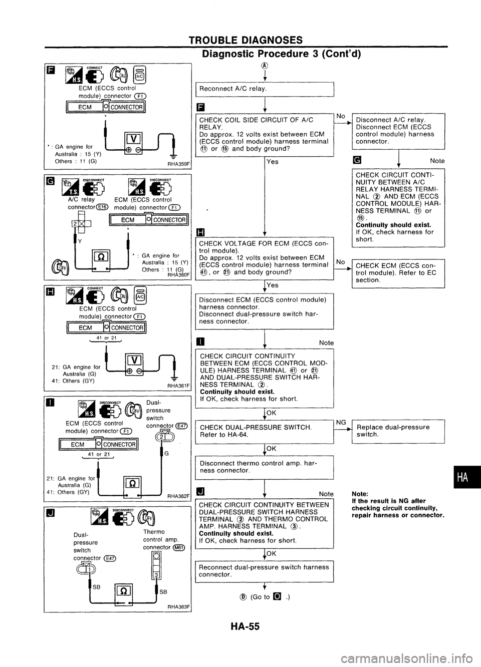
TROUBLE
DIAGNOSES
Diagnostic Procedure3(Conl'd)
@
~
I
Reconnect AICrelay. _
Ii
!
RHA359F
RHA362F
II
RHA361F
G
Dual-
pressure
switch
connector@
~.
S8
Thermo
control amp.
OOD
tm
@
•
:GA engine for
Australia :15 (Y)
Others :11 (G)
RHA360F
S8
Dual-
pressure
switch
connector
@
d))
~15@a
EGM (EGGS control
module) connec1or@
EGM
E[CONNECTORII
41 or21
.
II
•
:GA engine for
Australia: 15(Y)
Others :11 (G)
21: GAengine for
Australia (G)
41: Others (GY)
~&)
~Io
AlG relay EGM(EGGS control
connector@ module)connector@
ci
II
EGM
]g
CONNECTOR
II
Y
21: GAengine for
Australia (G)
41: Others (GY)
Ii
~i)@a~
EGM (EGGS control
module) connector @
II
EGM
]g
CONNECTOR
II
o
III
~i)
@a~
EGM (EGGS control
module) connector@
II
EGM 'gCONNECTORII
41 or21
.
RHA363F HA-55
Page 1461 of 1701
TROUBLEDIAGNOSES
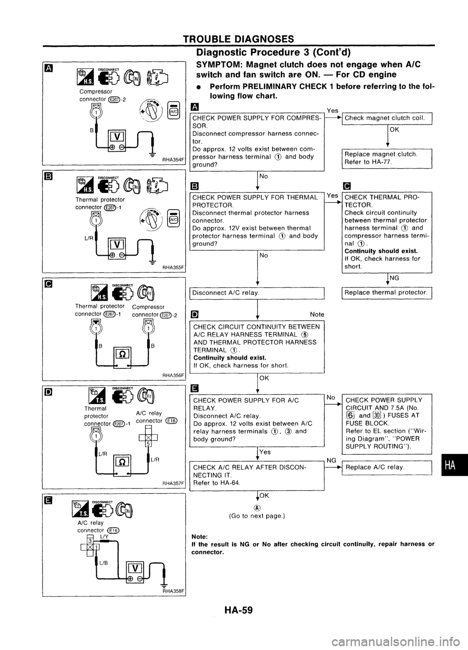
Diagnostic Procedure3(Cont'd)
SYMPTOM: Magnetclutchdoesnotengage whenAle
switch andfanswitch areON. -For CDengine
• Perform PRELIMINARY CHECK1before referring tothe fol-
lowing flowchart.
Compressor
connector
@Q7>-2
~ B
Thermal protector
connector
@Q7>-1
~
LlR
RHA354F
RHA355F
m
CHECK POWER SUPPLY FORCOMPRES-
SOR. Disconnect compressor harnessconnec-
tor. Do approx. 12volts exist between com-
pressor harness terminal
CD
and body
ground?
No
(;J
CHECK POWER SUPPLY FORTHERMAL
PROTECTOR.
Disconnect thermalprotector harness
connector. Do approx. 12Vexist between thermal
protector harnessterminal
G)
and body
ground?
NoYes
Check magnet clutchcoil.
OK
Replace magnetclutch.
Refer toHA-77.
[!]
Yes CHECK THERMAL PRO-
TECTOR. Check circuitcontinuity
between thermalprotector
harness terminal
G)
and
compressor harnesstermi-
nal
CD.
Continuity shouldexist.
If OK. check harness for
short.
NG
Disconnect AICrelay.
I
Replace thermalprotector.
Thermal protector Compressor
connector@-1 connector@QD-2
j. ~~
1-
I1iJ
RHA356F Note
CHECK CIRCUIT CONTINUITY BETWEEN
AIC RELAY HARNESS TERMINAL
@)
AND THERMAL PROTECTOR HARNESS
TERMINAL G).
Continuity shouldexist.
If OK. check harness forshort.
OK
Thermal
protector AlCrelay
connector @:>-1connector
@])
~ ciP
~/R ~
1
~L1R
RHA357FCHECK
POWER SUPPLY FORAIC
RELAY.
Disconnect AICrelay.
Do approx. 12volts exist between AIC
relay harness terminals
CD.
@and
body ground?
Yes
CHECK AICRELAY AFTERDISCON-
NECTING IT.
Refer toHA-64. No
NG CHECK
POWER SUPPLY
CIRCUIT AND7.5A(No.
~J
and
00)
FUSES AT
FUSE BLOCK.
Refer toEL section ("Wir-
ing Diagram", "POWER
SUPPLY ROUTING").
Replace AICrelay.
•
RHA358F OK
@
(Go tonext page.)
Note:
If
the result isNG orNo after checking circuitcontinuity, repairharness or
connector.
HA-59
Page 1462 of 1701
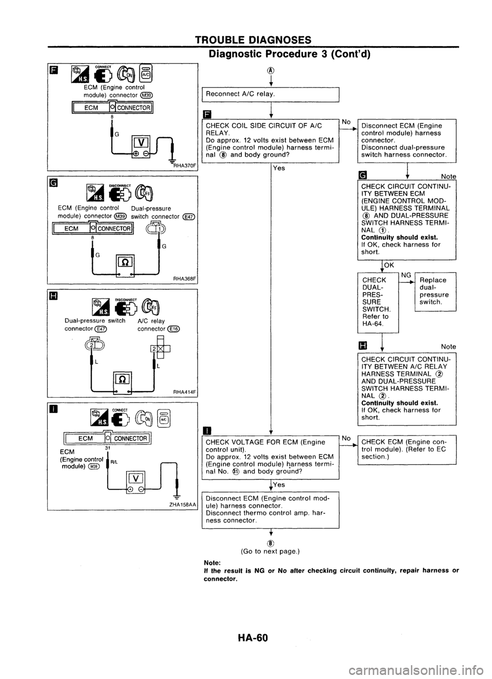
DisconnectECM(Engine
control module) harness
connector. Disconnect dual-pressure
switch harness connector .
Ii
~i)~@
ECM (Engine control
module) connector
@
II
ECM
E[CONNECTORII
8
G TROUBLE
DIAGNOSES
Diagnostic Procedure3(Cont'd)
@
+
I
Reconnect AICrelay.
Ii
r---
CHECK COILSIDECIRCUIT OFAIC No
RELAY.
Do approx. 12Yolts existbetween ECM
(Engine controlmodule) harnesstermi-
nal
@
and body ground?
G
G
ECM
(Engine control Dual-pressure
module) connector ~switch connector
@)
II
ECM
HCONNECTORII ~
8
[iJ
Note
CHECK CIRCUIT CONTINU-
ITY BETWEEN ECM
(ENGINE CONTROL MOD-
ULE) HARNESS TERMINAL
@ AND DUAL-PRESSURE
SWITCH HARNESS TERMI-
NAL G).
Continuity shouldexist.
If OK, check harness for
short.
Yes
....
RHA370F
OK
Dual-pressure switch
connector@ RHA368F
AlC relay
connector@ CHECK
DUAL-
PRES-
SURE
SWITCH. Refer to
HA-64.
NG
Replace
dual-
pressure
switch.
Note
~i5~~
ECM
11
CONNECTOR
II
31
o
L
II
ECM
(Engine control
AIL
module)@ L
RHA414F
o
CHECK VOLTAGE FORECM (Engine
control unit).
Do approx. 12YOIts exist between ECM
(Engine controlmodule) Ilarnesstermi-
nal No.
@
and body ground?
Yes
-=
Disconnect ECM(Engine controlmod-
ZHA158AA ule)harness connector.
Disconnect thermocontrolamp.har-
ness connector. No
CHECK
CIRCUIT CONTINU-
ITY BETWEEN AICRELAY
HARNESS TERMINAL
@
AND DUAL-PRESSURE
SWITCH HARNESS TERMI-
NAL
@.
Continuity shouldexist.
If OK, check harness for
short.
CHECK ECM(Engine con-
trol module). (RefertoEC
section.)
@
(Go tonext page.)
Note:
If the result isNG orNo after checking circuitcontinuity, repairharness or
connector.
HA-60
Page 1463 of 1701
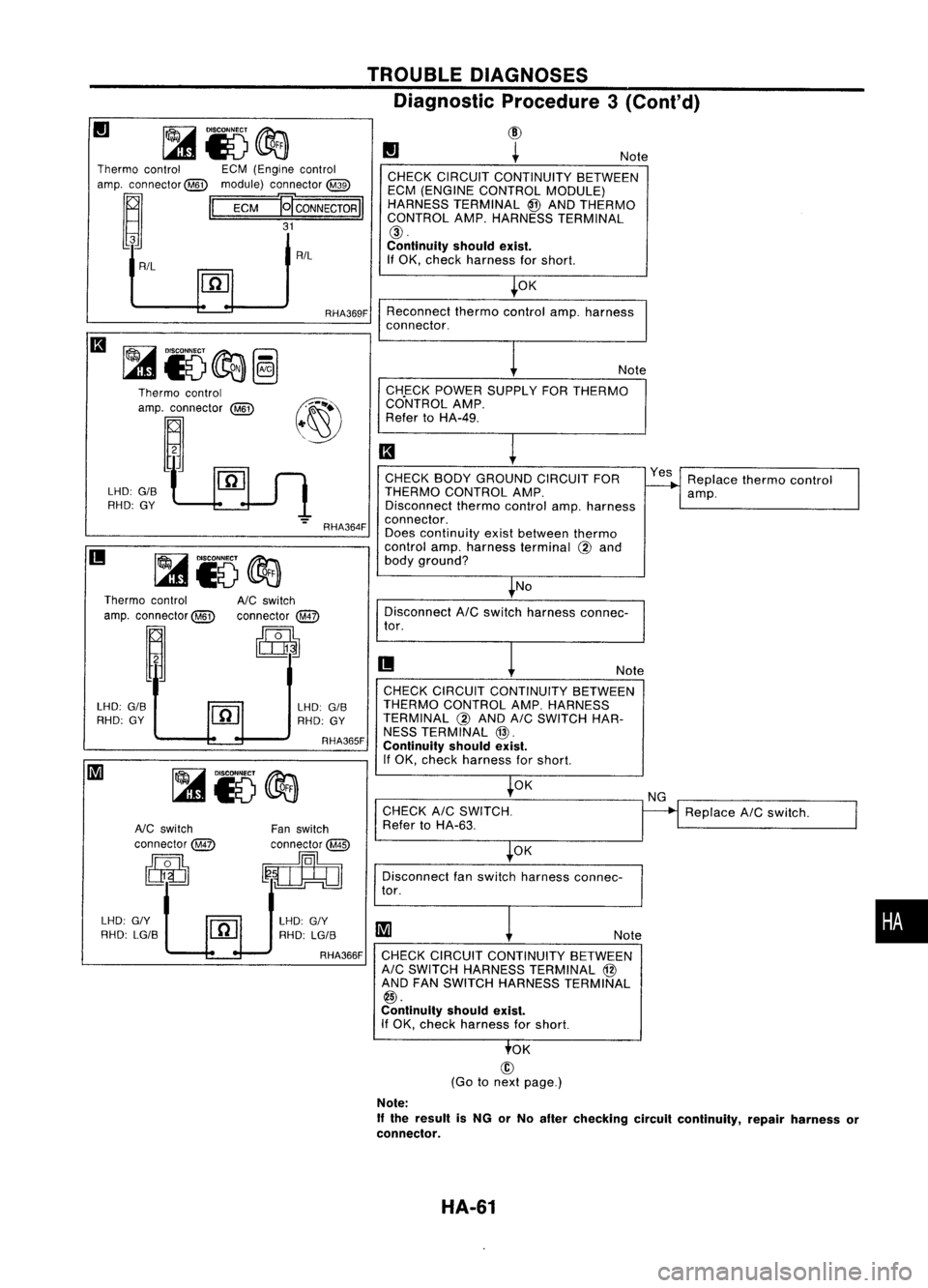
Replacethermocontrol
amp.
Note
No Note
CHECK POWER SUPPLY FORTHERMO
Co"NTROL AMP.
Refer toHA-49.
Reconnect
thermocontrolamp.harness
connector.
CHECK BODYGROUND CIRCUITFOR
THERMO CONTROL AMP.
Disconnect thermocontrolamp.harness
connector.
Does continuity existbetween thermo
control amp.harness terminal
@
and
body ground? OK
CHECK
CIRCUIT CONTINUITY BETWEEN
ECM (ENGINE CONTROL MODULE)
HARNESS TERMINAL @AND THERMO
CONTROL AMP.HARNESS TERMINAL
@.
Continuity shouldexist.
If OK, check harness forshort.
II
TROUBLE
DIAGNOSES
Diagnostic Procedure3(Conl'd)
(!)
~
RHA364F
:~~~~~;;:~:
@)~
LHO:
G/S'~
rn
(l
RHO: GY'L-.D--J
1
Thermo
control ECM(Engine control
amp. connector@) module)connector
@
~ II
ECM ?,CONNECTOOII
I
AIL ~_tR/L
II
II
DisconnectAICswitch harness connec-
tor.
Thermo
control
amp. connector @)
~
A/C
switch
connector
@
~
II
Note
LHO: GIS
RHO: GY LHO:
GIS
RHO: GY
RHA365F CHECK
CIRCUIT CONTINUITY BETWEEN
THERMO CONTROL AMP.HARNESS
TERMINAL
@
AND AICSWITCH HAR-
NESS TERMINAL
@.
Continuity shouldexist.
If OK, check harness forshort.
•
Replace
AICswitch.
Note
OK
OK
CHECK
AICSWITCH.
Refer toHA-63.
Disconnect fanswitch harness connec-
tor.
LHO: G/Y
RHO: LG/S
Fan
switch
connector
@ID
~
RHA366F CHECKCIRCUIT CONTINUITY BETWEEN
AIC SWITCH HARNESS TERMINAL @
AND FANSWITCH HARNESS TERMINAL
@.
Continuity shouldexist.
If OK, check harness forshort.
NC
switch
connector@
[ij
LHO: G/Y
RHO: LG/S
OK
@
(Go tonext page.)
Note:
If
the result isNG orNo after checking circuitcontinuity, repairharness or
connector.
HA-61
Page 1465 of 1701
Circuitcheck
~
AlC switch
connector TROUBLE
DIAGNOSES
Electrical Components Inspection(Cont'd)
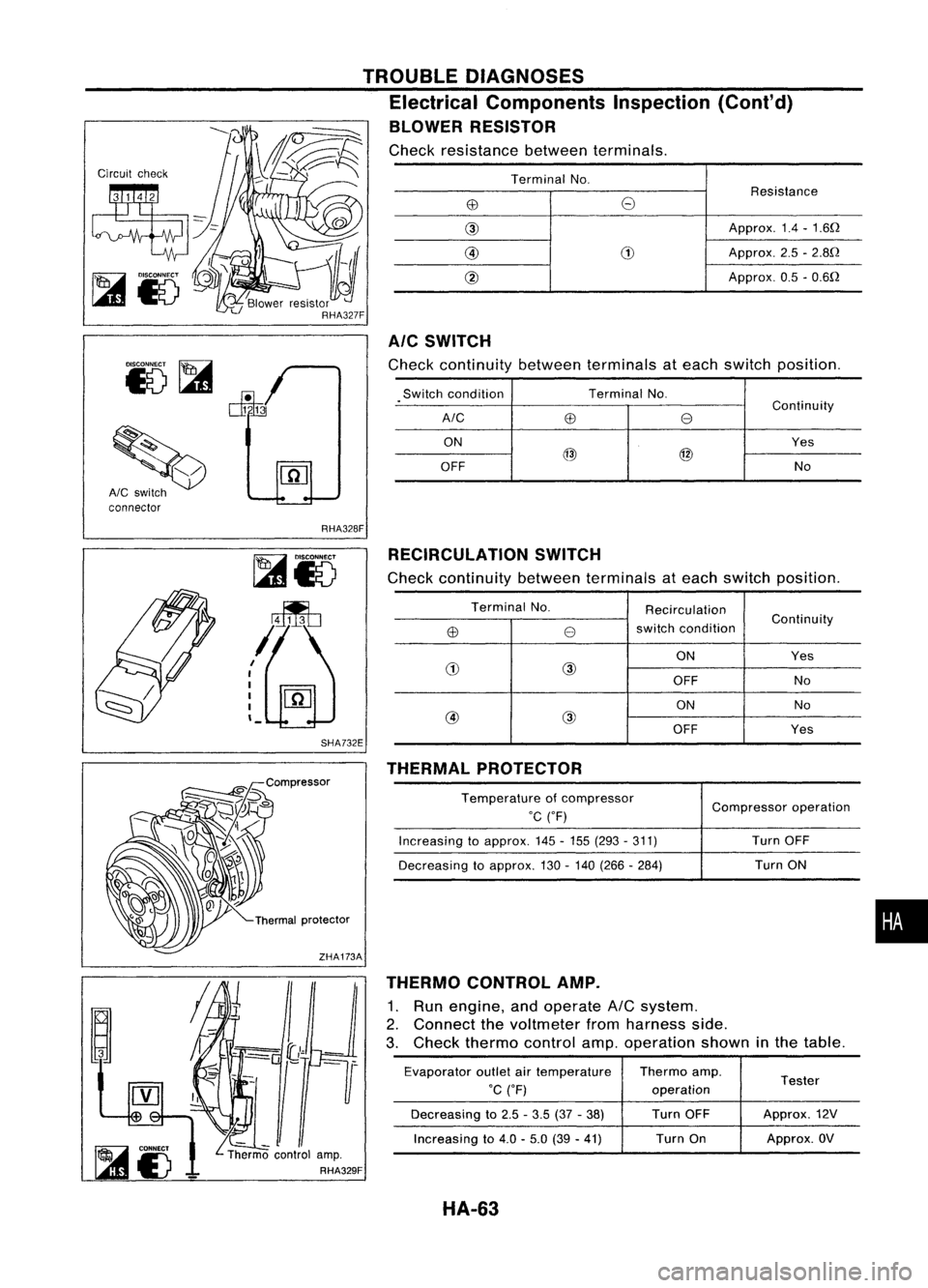
BLOWER RESISTOR
Check resistance betweenterminals.
Terminal No.
Resistance
EB
8
@
Approx.1.4-1.6Q
@
(1)
Approx.2.5-2.8Q
@
Approx.0.5-0.6Q
AIC SWITCH
Check continuity betweenterminals ateach switch position.
.
Switch
condition TerminalNo.
Continuity
A/C
EB
e
ON Yes
@
@
OFF No
RHA328F RECIRCULATION SWITCH
Check continuity betweenterminals ateach switch position.
I
I
I
I
I
'-
SHA732E
Terminal
No.
Recirculation
switch condition Continuity
EB
e
ON Yes
(1)
@
OFF No
ON No
@ @
OFF Yes
THERMAL PROTECTOR
THERMO CONTROL AMP.
1. Run engine, andoperate
AIC
system.
2. Connect thevoltmeter fromharness side.
3. Check thermo controlamp.operation showninthe table.
Evaporator outletairtemperature Thermoamp.
Tester
°C CF) operation
Decreasing to2.5 -3.5 (37-38) TurnOFF Approx.
12V
Increasing to4.0 -5.0 (39-41) Turn
On Approx.OV
Temperature
ofcompressor
°C
(OF)
Increasing toapprox. 145-155 (293 -311)
Decreasing toapprox. 130-140 (266 -284) Compressor
operation
Turn OFF
Turn ON
•
HA-63
Page 1469 of 1701
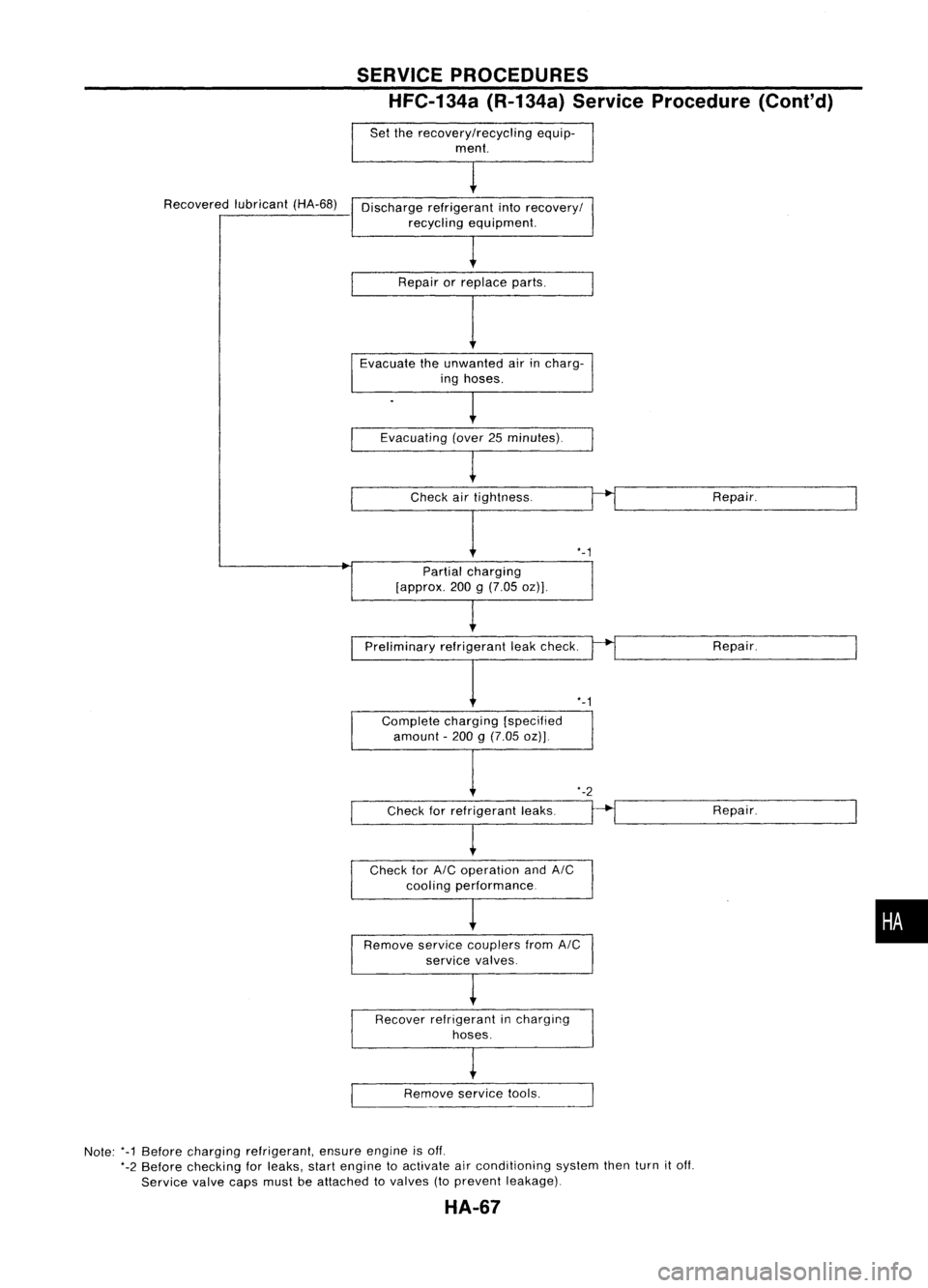
Recoveredlubricant(HA-68)
SERVICE
PROCEDURES
HFC-134a (R-134a)ServiceProcedure (Cont'd)
Set therecoverylrecycling equip-
ment.
Discharge refrigerant into
recoveryl
recycling equipment.
Repair orreplace parts.
Evacuate theunwanted airincharg-
ing hoses.
Evacuating (over25minutes).
Check airtightness.
I
Partial charging
[approx. 200g(7.05 oz)J.
'-1
Repair.
Preliminary refrigerantleakcheck.
,-1
Complete charging[specified
amount -200 g(7.05 oz)J. Repair.
'-2
---C-h-e-c-k-f-o-r -re-f-r-ig-e-r-a-nt-Ie-a-k-s-.
--H
Repair.
--r.---~. '---.---
Check for
AIC
operation and
AIC
cooling performance
Remove servicecouplers from
AIC
service valves.
Recover refrigerant incharging
hoses.
Remove servicetools.
Note: '-1Before charging refrigerant, ensureengineisoff.
'-2 Before checking forleaks, startengine toactivate airconditioning systemthenturnitoff.
Service valvecapsmustbeattached tovalves (toprevent leakage).
HA-67
•