1995 NISSAN ALMERA N15 check engine
[x] Cancel search: check enginePage 1610 of 1701
PRECAUTIONSANDPREPARATION
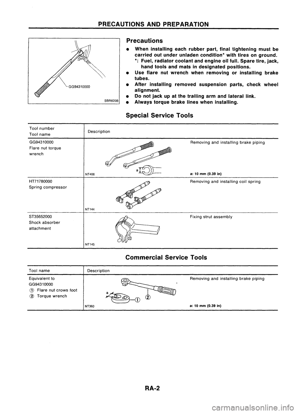
SBR820B Precautions
• When installing eachrubber part,finaltightening mustbe
carried outunder unladen condition* withtires onground.
*:
Fuel, radiator coolantandengine oilfull. Spare tire,jack,
hand tools andmats indesignated positions.
• Use flare nutwrench whenremoving orinstalling brake
tubes.
• After installing removedsuspension parts,check wheel
alignment.
• Donot jack upatthe trailing armandlateral link.
• Always torquebrakelineswhen installing.
Special Service Tools
Tool number
Tool name Description
GG9431 0000
Flare nuttorque
wrench
HT71780000
Spring compressor
ST35652000
Shock absorber
attachment
NT406
NT144
NT145
Removing
andinstalling brakepiping
a:
10
mm
(0.39
in)
Removing andinstalling coilspring
Fixing strutassembly
Tool name
Description
Commercial
ServiceTools
Equivalent to
GG9431 0000
G)
Flare nutcrows
foot
@
Torque wrench Removing
andinstalling brakepiping
NT360
a:
10
mm
(0.39
in)
RA-2
Page 1613 of 1701
ON-VEHICLESERVICE
Rear Wheel Alignment
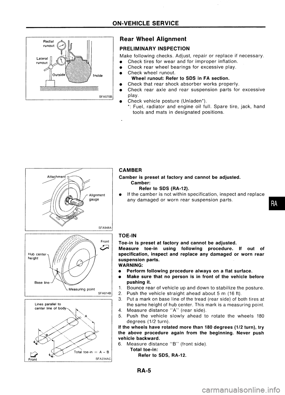
PRELIMINARY INSPECTION
Make following checks.Adjust,repairorreplace ifnecessary.
• Check tiresforwear andforimproper inflation.
• Check rearwheel bearings forexcessive play.
• Check wheelrunout.
Wheel runout: RefertoSOS inFA section.
• Check thatrear shock absorber worksproperly.
• Check rearaxleandrear suspension partsforexcessive
SFA575B
play.
• Check vehicle posture (Unladen*).
*: Fuel, radiator andengine oilfull. Spare tire,jack, hand
tools andmats indesignated positions.
•
CAMBER
Camber ispreset atfactory andcannot beadjusted.
Camber: Refer toSOS (RA-12).
• Ifthe camber isnot within specification, inspectandreplace
any damaged orworn rearsuspension parts.
TOE-IN
Toe-in ispreset atfactory andcannot beadjusted.
Measure toe-inusingfollowing procedure. Ifout of
specification, inspectandreplace anydamaged orworn rear
suspension parts.
WARNING:
• Perform following procedure alwaysonaflat surface.
• Make surethatnoperson isin front ofthe vehicle before
pushing it.
1. Bounce rearofvehicle upand down tostabilize theposture.
2. Push thevehicle straight aheadabout5m (16
ft).
3. Putamark onbase lineofthe tread (rearside) ofboth tires at
the same height ofhub center. Thismark isameasuring point.
4. Measure distance"A"(rear side).
5. Push thevehicle slowlyaheadtorotate thewheels 180
degrees (1/2turn).
If the wheels haverotated morethan180degrees (1/2turn), try
the above procedure againfromthebeginning. Neverpush
vehicle backward.
6. Measure distance"B"(front side).
Total toe-in:
Refer toSOS, RA-12.
Front
SFA948A
SFA614B
SFA234AC
Lines
parallel to
center lineofbOdY~
Q
Front
Hub
center
height
RA-5
Page 1667 of 1701
STEERINGSYSTEM
SECTIONST
CONTENTS
PRECAUTIONS ANDPREPARATION 2
Precautions 2
Special Service Tools 3
Commercial ServiceTools 4
ON-VEHICLE SERVICE
5
Checking SteeringWheelPlay 5
Checking NeutralPosition onSteering Wheel 5
Front Wheel Turning Angle 5
Checking GearHousing Movement 5
Checking andAdjusting DriveBelts(For
power steering) 6
Checking FluidLevel 6
Checking FluidLeakage 6
Bleeding Hydraulic System 7
Checking SteeringWheelTurning Force(For
power steering) 7
Checking Hydraulic System 8
STEERING WHEElANDSTEERING COLUMN 9
Removal andInstallation 9
Disassembly andAssembly 12
Inspection 13
MANUAL STEERING GEARANDLINKAGE
(Model R24N) 14
Removal
andInstallation 14
Disassembly 15
Inspection 15
Assembly andAdjustment... 16
POWER STEERING GEARANDLINKAGE (Model
PR24AC) 19
Removal andInstallation 19
Disassembly 22
Inspection 22
Assembly ,.. 23
Adjustment 27
POWER STEERING OILPUMP 29
Pre-disassembly Inspection 30
Disassembly 30
Inspection 31
Assembly 31
POWER STEERING OILCOOLER
33
Oil Cooler (Heavy dutykitfor CD20 engine
model) 33
Removal andInstallation 33
SERVICE DATAANDSPECIFICATIONS
(505)34
General Specifications 34
Inspection andAdjustment 34
•
Page 1672 of 1701
ON-VEHICLESERVICE
Checking andAdjusting DriveBelts(Forpower
steering)
Refer to"Checking DriveBelts" for"ENGINE MAINTENANCE"
in MA section.
SST476C
S
r
SST681B Checking
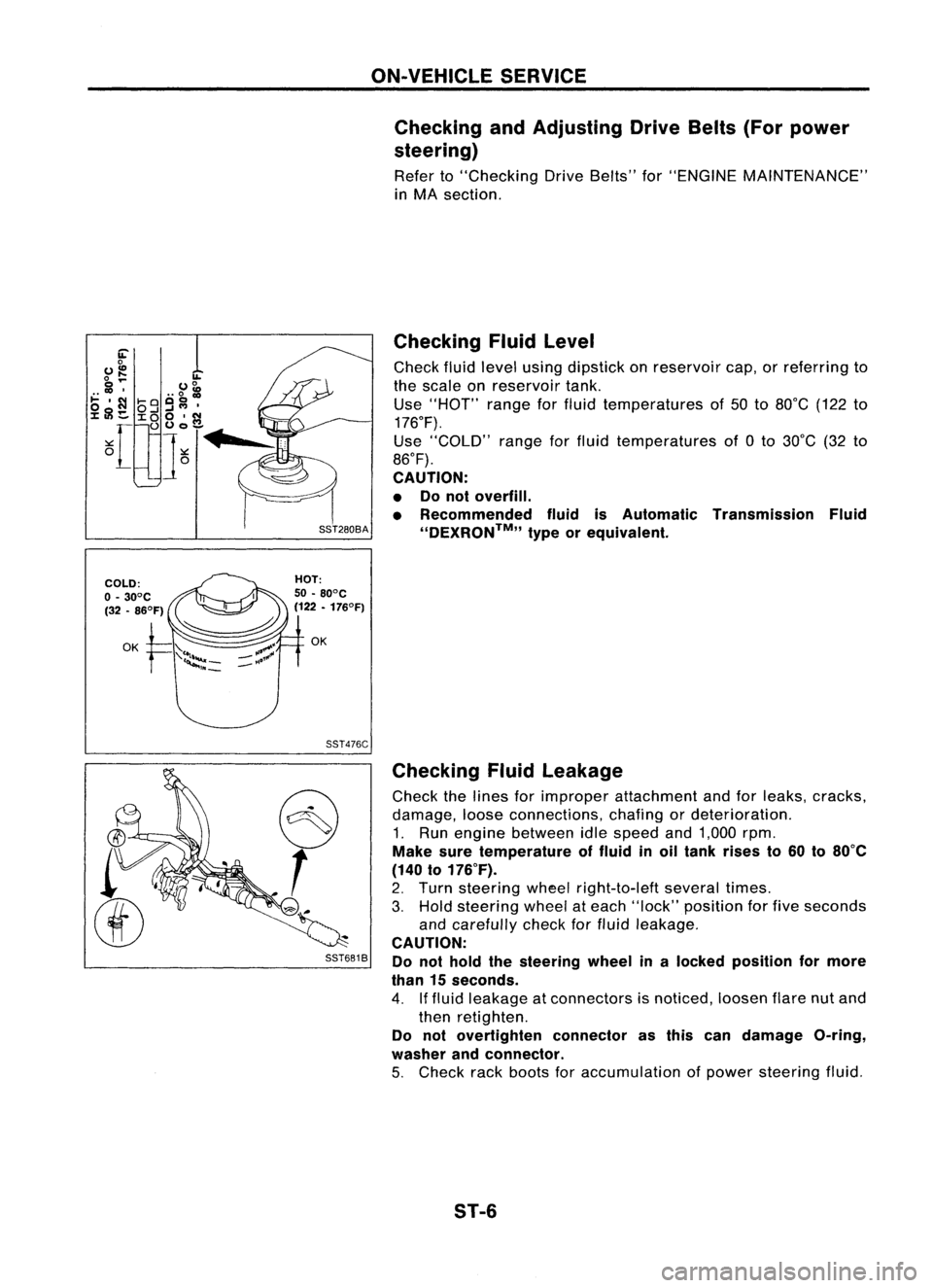
Fluidlevel
Check fluidlevel using dipstick onreservoir cap,orreferring to
the scale onreservoir tank.
Use "HOT" rangeforfluid temperatures of50 to80°C (122to
176°F).
Use "COLD" rangeforfluid temperatures of0to 30°C (32to
86°F).
CAUTION:
• Donot overfill.
• Recommended fluidisAutomatic Transmission Fluid
''DEXRON™,, typeorequivalent.
Checking Fluidleakage
Check thelines forimproper attachment andforleaks, cracks,
damage, looseconnections, chafingordeterioration.
1. Run engine between idlespeed and1,000 rpm.
Make suretemperature offluid inoil tank rises to60 to80°C
(140 to176°F).
2. Turn steering wheelright-to-Ieft severaltimes.
3. Hold steering wheelateach "lock" position forfive seconds
and carefully checkforfluid leakage.
CAUTION:
Do not hold thesteering wheelinalocked position formore
than 15seconds.
4. Iffluid leakage atconnectors isnoticed, loosenflarenutand
then retighten.
Do not overtighten connectorasthis candamage O-ring,
washer andconnector.
5. Check rackboots foraccumulation ofpower steering fluid.
ST-6
Page 1673 of 1701
SST491B
SST090B ON-VEHICLE
SERVICE
Bleeding Hydraulic System
1. Raise frontendofvehicle untilwheels areclear ofthe
ground.
2. Add fluid intooiltank tospecified level.Thenquickly turn
steering wheelfullytoright andleftand lightly touchsteer-
ing stoppers.
Repeat steering wheeloperation untilfluid level nolonger
decreases.
3. Start engine.
Repeat step2.above.
• Incomplete airbleeding willcause thefollowing tooccur.
When thishappens, bleedairagain.
a. Air bubbles inreservoir tank
b. Clicking noiseinoil pump
c. Excessive buzzinginoil pump
Fluid noise mayoccur inthe valve oroil pump. Thisiscommon
when thevehicle isstationary orwhile turning thesteering
wheel slowly. Thisdoes notaffect theperformance ordurabil-
ity ofthe system.
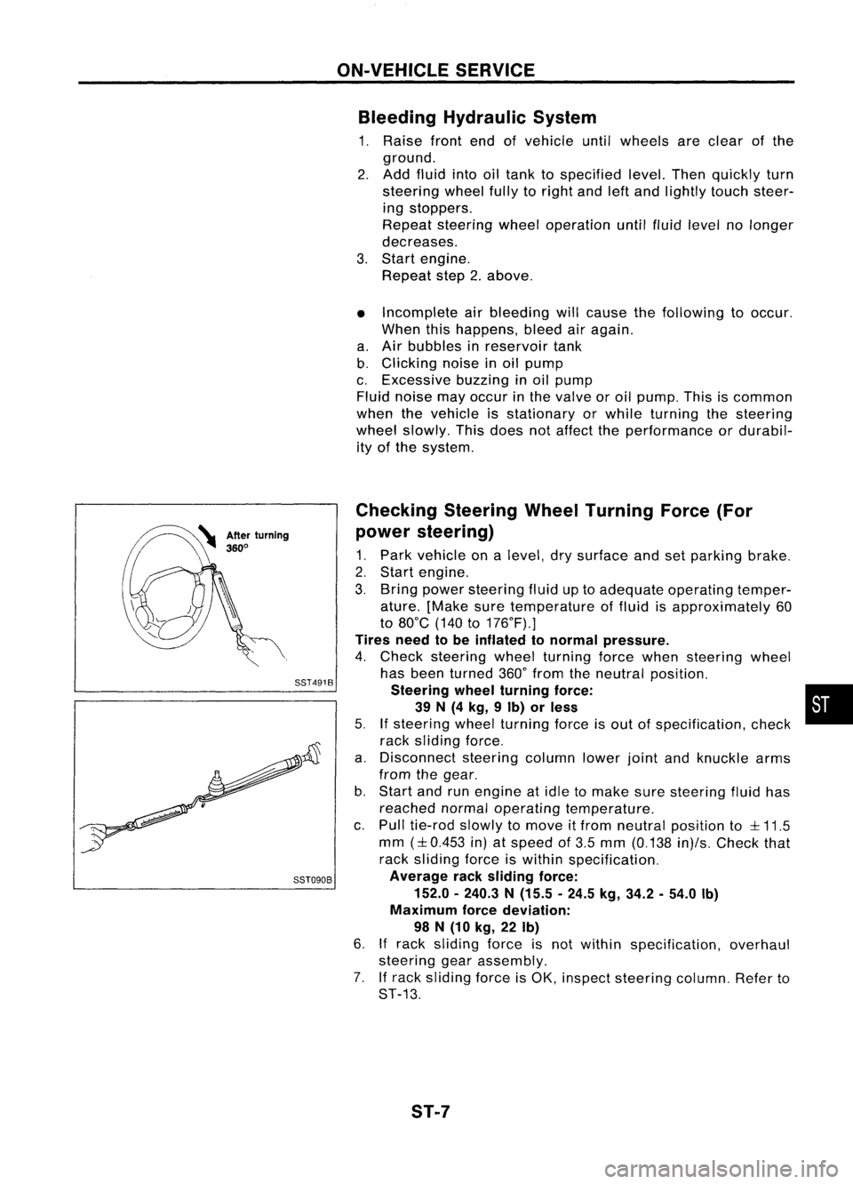
Checking SteeringWheelTurning Force(For
power steering)
1. Park vehicle onalevel, drysurface andsetparking brake.
2. Start engine.
3. Bring power steering fluiduptoadequate operating temper-
ature. [Make suretemperature offluid isapproximately 60
to 80°C (140to176°F).]
Tires needtobe inflated tonormal pressure.
4. Check steering wheelturning forcewhen steering wheel
has been turned 360°from theneutral position.
Steering wheelturning force: •
39 N(4 kg, 9Ib) orless
5.
If
steering wheelturning forceisout ofspecification, check
rack sliding force.
a. Disconnect steeringcolumnlowerjointandknuckle arms
from thegear.
b. Start andrunengine atidle tomake suresteering fluidhas
reached normaloperating temperature.
c. Pull tie-rod slowlytomove itfrom neutral position to
::l::
11.5
mm
(::l::
0.453 in)atspeed of3.5 mm (0.138 in)/s.Check that
rack sliding forceiswithin specification.
Average racksliding force:
152.0 -240.3 N(15.5 -24.5 kg,34.2 -54.0 Ib)
Maximum forcedeviation:
98 N(10 kg, 22Ib)
6.
If
rack sliding forceisnot within specification, overhaul
steering gearassembly.
7. Ifrack sliding forceisOK, inspect steering column.Referto
ST-13.
ST-7
Page 1674 of 1701
ST27091000
.. :Direction ofoil flow Low-pressure
hose SST834-AON-VEHICLE
SERVICE
Checking Hydraulic System
Before starting, checkbelttension, drivingpulleyandtirepres-
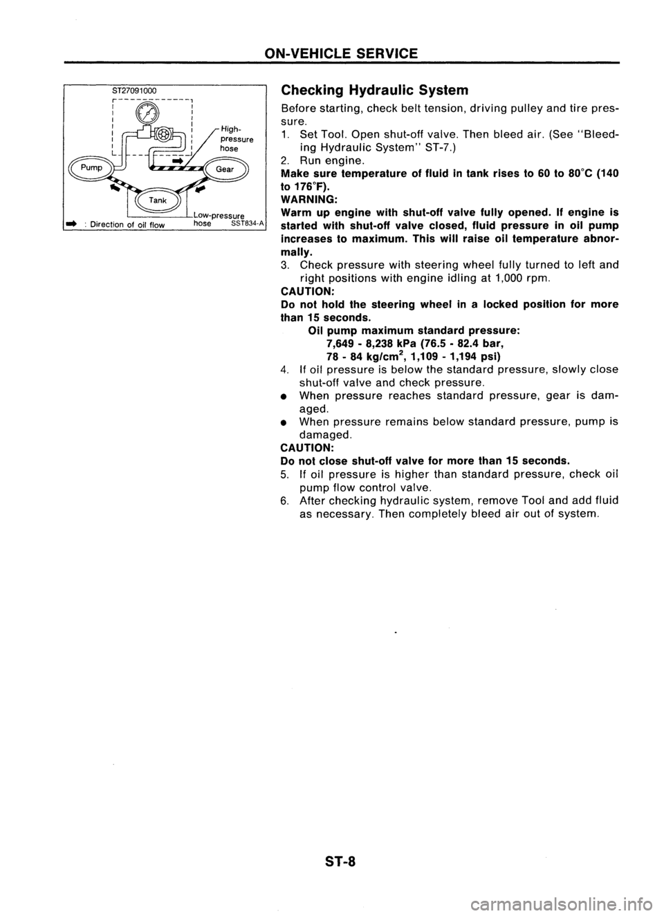
sure. 1. Set Tool. Open shut-off valve.Thenbleed air.(See "Bleed-
ing Hydraulic System"ST-7.)
2. Run engine.
Make suretemperature offluid intank rises to60 to80°C (140
to 176°F).
WARNING:
Warm upengine withshut-off valvefullyopened. Ifengine is
started withshut-off valveclosed, fluidpressure inoil pump
increases tomaximum. Thiswillraise oiltemperature abnor-
mally.
3. Check pressure withsteering wheelfullyturned toleft and
right positions withengine idlingat1,000 rpm.
CAUTION:
Do not hold thesteering wheelinalocked position formore
than 15seconds.
Oil pump maximum standardpressure:
7,649 -8,238 kPa(76.5 .82.4 bar,
78 -84 kg/cm
2,
1,109-1,194 psi)
4.
If
oil pressure isbelow thestandard pressure, slowlyclose
shut-off valveandcheck pressure.
• When pressure reachesstandard pressure, gearisdam-
aged.
• When pressure remainsbelowstandard pressure, pumpis
damaged.
CAUTION: Do not close shut-off valveformore than15seconds.
5.
If
oil pressure ishigher thanstandard pressure, checkoil
pump flowcontrol valve.
6. After checking hydraulic system,removeToolandaddfluid
as necessary. Thencompletely bleedairout ofsystem.
S1-8
Page 1694 of 1701
POWERSTEERING GEARANDLINKAGE (ModelPR24AC)
Adjustment (Cont'd)
6. Move rackover itsentire stroke several times.
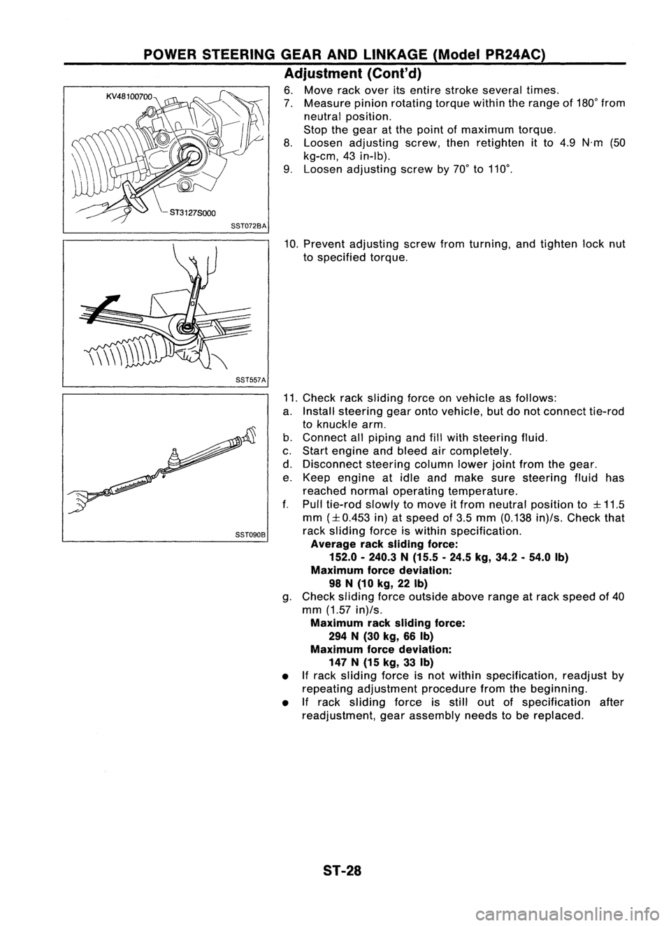
7. Measure pinionrotating torquewithintherange of180° from
neutral position.
Stop thegear atthe point ofmaximum torque.
8. Loosen adjusting screw,thenretighten itto 4.9 N'm (50
kg-em, 43in-Ib).
9. Loosen adjusting screwby70° to110°.
SST072BA
10.Prevent adjusting screwfromturning, andtighten locknut
to specified torque.
SST557A
SST090B
11.
Check racksliding forceonvehicle asfollows:
a. Install steering gearontovehicle, butdonot connect tie-rod
to knuckle arm.
b. Connect allpiping andfillwith steering fluid.
c. Start engine andbleed aircompletely.
d. Disconnect steeringcolumnlowerjointfrom thegear.
e. Keep engine atidle and make suresteering fluidhas
reached normaloperating temperature.
f. Pull tie-rod slowlytomove itfrom neutral position to
:l:
11.5
mm
(:l:
0.453 in)atspeed of3.5 mm (0.138 in)/s.Check that
rack sliding forceiswithin specification.
Average racksliding force:
152.0 -240.3 N(15.5 .24.5 kg,34.2.54.0 Ib)
Maximum forcedeviation:
98 N(10 kg,22Ib)
g. Check sliding forceoutside aboverangeatrack speed of40
mm (1.57 in)/s.
Maximum racksliding force:
294 N(30 kg, 66Ib)
Maximum forcedeviation:
147 N(15 kg, 33Ib)
• Ifrack sliding forceisnot within specification, readjustby
repeating adjustment procedurefromthebeginning.
• If
rack sliding forceisstill outofspecification after
readjustment, gearassembly needstobe replaced.
ST-28
Page 1699 of 1701
POWERSTEERING OILCOOLER
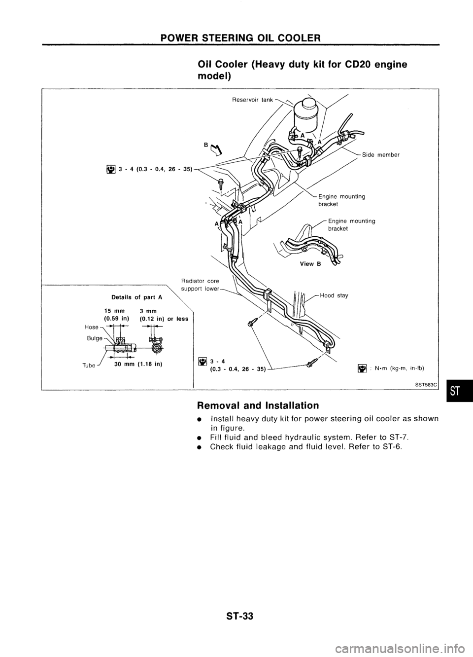
Oil Cooler (Heavy dutykitfor CD20 engine
model)
Removal andInstallation
• Install heavydutykitfor power steering oilcooler asshown
in figure.
• Fill fluid andbleed hydraulic system.RefertoST-7.
• Check fluidleakage andfluid level. Refer toST-6.
Hose
Bulge
Tube
~
3-4 (0.3 -0.4, 26-35)
Details ofpart A
15
mm
3
mm
(0.59 in) (0.12in)orless
.1 I-
30
mm
(1.18
in)
Reservoir
lank
~ 3-4
(0.3 -0.4, 26-35)
~
Enginemounting
/~bracket
\~ ~~eWB~
~•N.m (kg-m, in-Ib)
SST583C
•
ST-33