1995 NISSAN ALMERA N15 check engine
[x] Cancel search: check enginePage 900 of 1701
•
INSPECTION
START
m
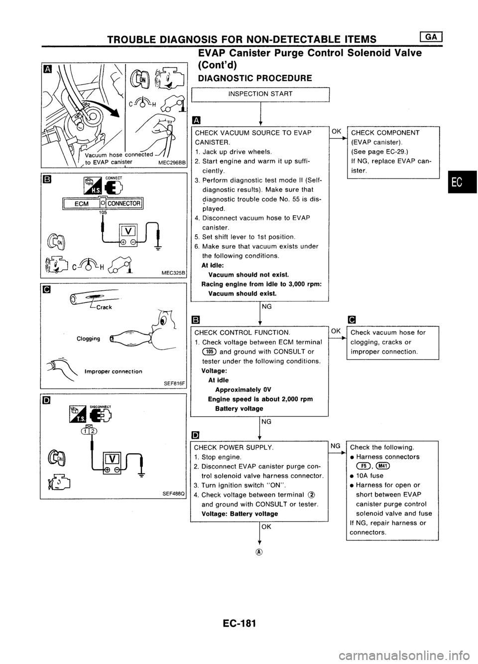
CHECK VACUUM SOURCETOEVAP OK
CHECK COMPONENT
CANISTER.
L---.
(EVAPcanister).
1. Jack updrive wheels. (See
page EC-29.)
2. Start engine andwarm itup suffi- If
NG, replace EVAPcan-
ciently. ister.
3. Perform diagnostic testmode II(Self-
diagnostic results).Makesurethat
9iagnostic troublecodeNo.55isdis-
played.
4. Disconnect vacuumhosetoEVAP
canister.
5. Set shift lever to1st position.
6. Make surethatvacuum existsunder
the following conditions.
At Idle:
Vacuum shouldnotexist.
Racing enginefromIdleto3,000 rpm:
Vacuum shouldexist.
NG
Ii)
[!J
CHECK CONTROL FUNCTION. OK
Check vacuum hosefor
1. Check voltage between ECMterminal
--..
clogging, cracksor
@
andground withCONSULTor improperconnection.
tester underthefollowing conditions.
Voltage: At idle
Approximately OV
Engine speedisabout 2,000rpm
Battery voltage
NG
I!l
CHECK POWER SUPPLY. NG
Check thefollowing.
1. Stop engine.
I-----.
•Harness connectors
2. Disconnect EVAPcanister purgecon-
QD,@
trol solenoid valveharness connector. •10A fuse
3. Turn ignition switch"ON". •
Harness foropen or
4. Check voltage between terminal
@
short
between EVAP
and ground withCONSULTor tester. canister
purgecontrol
Voltage: Batteryvoltage
solenoid
valveandfuse
r
K If
NG, repair harness or
connectors.
SEF816F
SEF488Q
MEC325B
MEC296BB
Clogging TROUBLE
DIAGNOSIS FORNON-DETECTABLE ITEMS
[ill
EVAP Canister PurgeControl Solenoid Valve
(Cont'd)
DIAGNOSTIC PROCEDURE
~i5
ECM
B
CONNECTOR
II
'f
~VV1
~ Crack
~i5
~
=:5---
~ Improperconnection
@
EC-181
Page 905 of 1701
INSPECTIONSTART
m
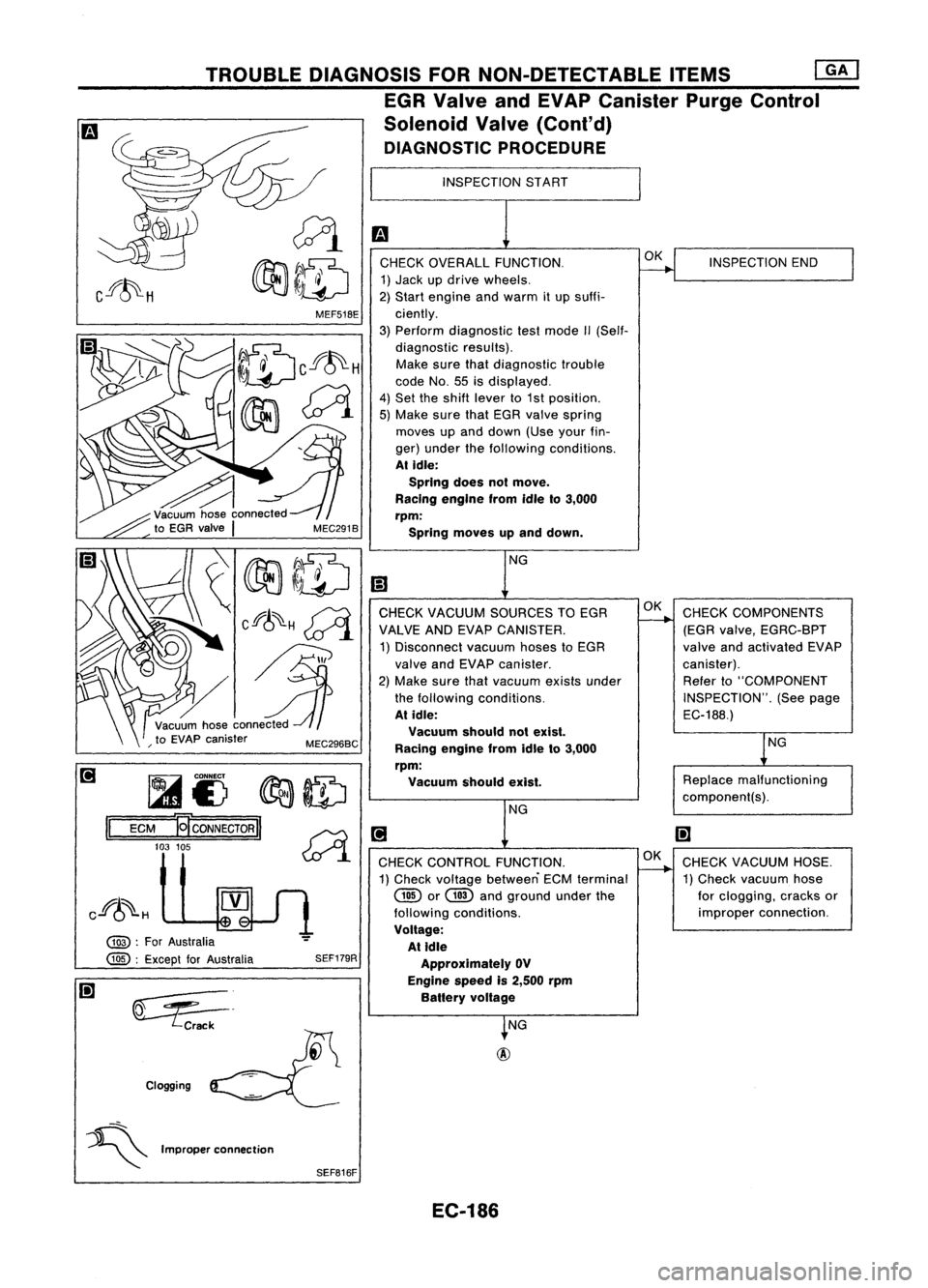
CHECK OVERALL FUNCTION.
~INSPECTION
END
1) Jack updrive wheels.
2) Start engine andwarm itup suffi-
ciently.
3) Perform diagnostic testmode II(Self-
diagnostic results).
Make surethatdiagnostic trouble
code No.55isdisplayed.
4) Set theshift lever to1st position.
5) Make surethatEGR valve spring
moves upand down (Useyourfin-
ger) under thefollowing conditions.
At idle:
SprIng doesnotmove.
RacIng engIne fromidleto3,000
rpm:
Spring moves upand down.
NG
l!1
CHECK VACUUM SOURCES TOEGR OK
CHECK COMPONENTS
VALVE ANDEVAP CANISTER.
-----...
(EGRvalve, EGRC-BPT
1) Disconnect vacuumhosestoEGR valveandactivated EVAP
valve andEVAP canister. canister).
2) Make surethatvacuum existsunder Refer
to"COMPONENT
the following conditions. INSPECTION".(Seepage
At idle:
EC-188.)
Vacuum shouldnotexist.
lNG
Racing engine fromidleto3,000
rpm: Vacuum shouldexist.
Replace
malfunctioning
component(s).
NG
[!J
I!l
CHECK CONTROL FUNCTION. OK
CHECK VACUUM HOSE.
1) Check voltage between ECMterminal
----..
1)Check vacuum hose
@
or
GID
andground underthe forclogging, cracksor
following conditions. improper
connection.
Voltage: At Idle
Approximately OV
Engine speedis2,500 rpm
Battery voltage
~NG
SEF179R
~=.
Crack
Clogging MEF51BE
TROUBLE
DIAGNOSIS FORNON-DETECTABLE ITEMS
[]K]
EGR Valve andEVAP Canister PurgeControl
Solenoid Valve(Cont'd)
DIAGNOSTIC PROCEDURE
~I)
~ID
ECM
-gcoNNEcTORII ~
103 105
~.1
@ :
For Australia
@ :
Except forAustralia
II
Cf~H
~
~ Improperconnection
SEFB16F
EC-186
Page 906 of 1701
•
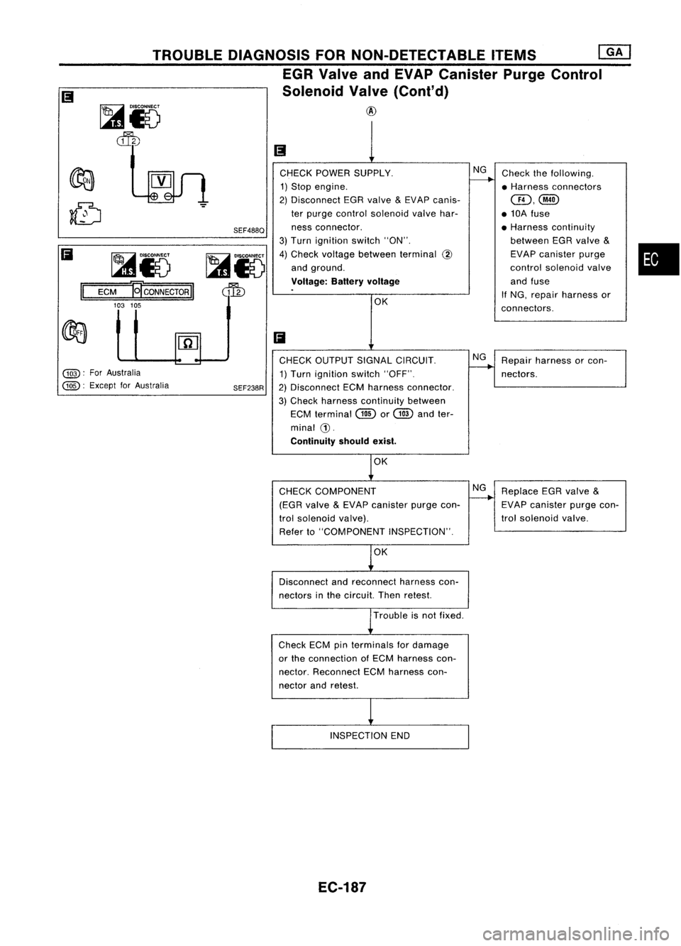
Check
thefollowing.
• Harness connectors
@,@
• 10A fuse
• Harness continuity
between EGRvalve
&
EVAP canister purge
control solenoid valve
and fuse
If
NG, repair harness or
connectors.
NG
OK
CHECK
POWER SUPPLY.
1) Stop engine.
2) Disconnect EGRvalve
&
EVAP canis-
ter purge control solenoid valvehar-
ness connector.
3) Turn ignition switch"ON".
4) Check voltage between terminal
@
and ground.
Voltage: Batteryvoltage
SEF488Q
~i8
dfu
TROUBLE
DIAGNOSIS FORNON-DETECTABLE ITEMS
[QK]
EGR Valve andEVAP Canister PurgeControl
Solenoid Valve(Cont'd)
@
~i8
~
~i5
ECM
]gCONNECTORII
103 105
II
Ii
Ii
@:
ForAustralia
@:
Except forAustralia CHECK
OUTPUT SIGNALCIRCUIT.
1) Turn ignition switch"OFF".
SEF238R
2)Disconnect ECMharness connector.
3) Check harness continuity between
ECM terminal Gillor
@
andter-
minal
G).
Continuity shouldexist. NG
Repair harness orcon-
nectors.
OK
CHECK COMPONENT
(EGR valve
&
EVAP canister purgecon-
trol solenoid valve).
Refer to"COMPONENT INSPECTION".
NG
Replace EGRvalve
&
EVAP canister purgecon-
trol solenoid valve.
OK
Disconnect andreconnect harnesscon-
nectors inthe circuit. Thenretest.
Trouble isnot fixed.
Check ECMpinterminals fordamage
or the connection ofECM harness con-
nector. Reconnect ECMharness con-
nector andretest.
INSPECTION END
EC-187
Page 910 of 1701
2:
1
:>
Q)
Ol
~
0
>
::;
c.
::;
0
,,"--
0
-
Rich- Idealratio _
Lean
Mixlure ratio
SEF288D
•
Zirconia
tube SEF406H
TROUBLE
DIAGNOSIS FORNON-DETECTABLE ITEMS
Heated Oxygen Sensor(H02S)(Cont'd)
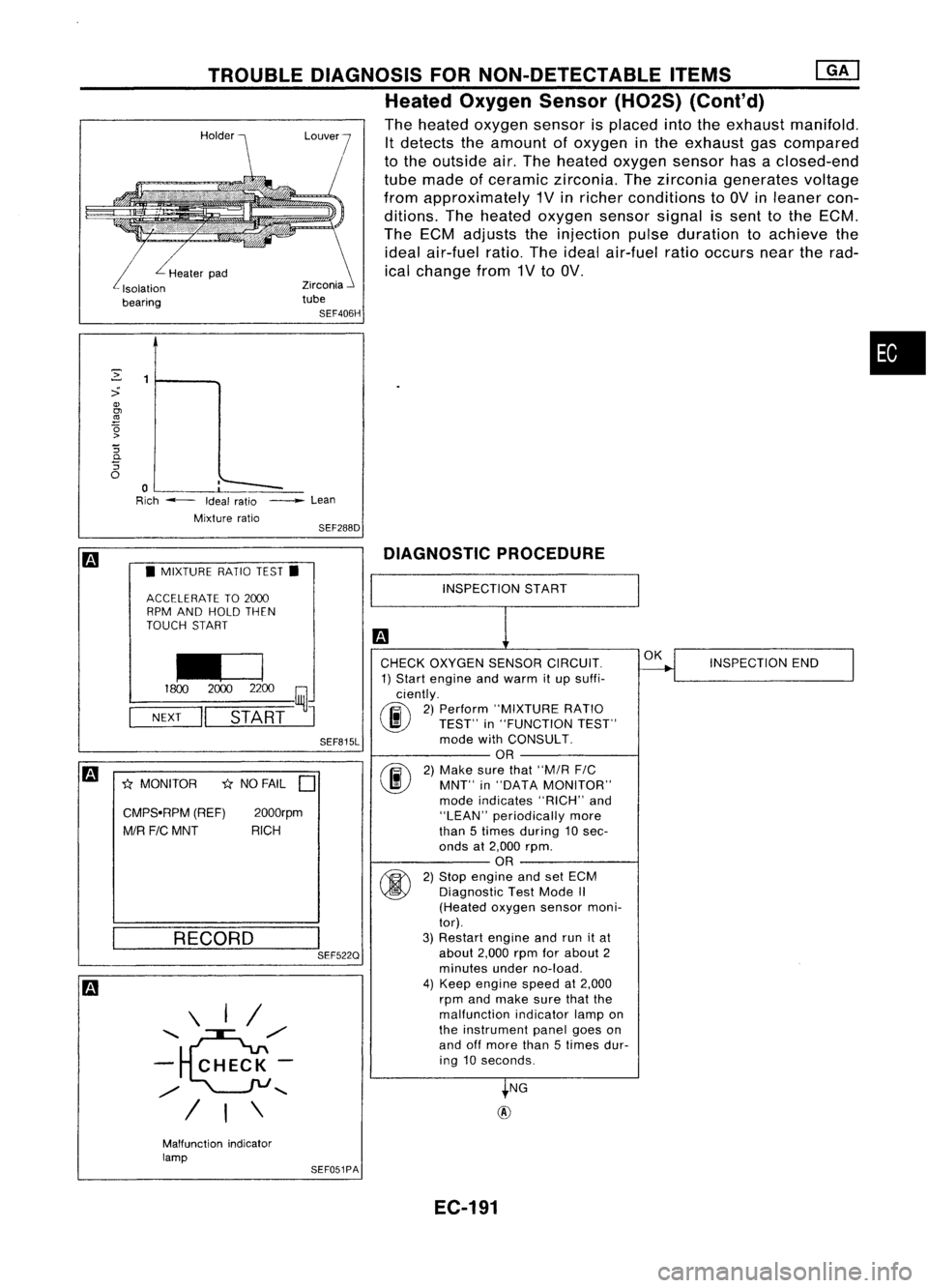
The heated oxygen sensorisplaced intotheexhaust manifold.
It detects theamount ofoxygen inthe exhaust gascompared
to the outside air.The heated oxygen sensorhasaclosed-end
tube made ofceramic zirconia. Thezirconia generates voltage
from approximately 1Vinricher conditions to
av
inleaner con-
ditions. Theheated oxygen sensorsignalissent tothe ECM.
The ECM adjusts theinjection pulseduration toachieve the
ideal air-fuel ratio.Theideal air-fuel ratiooccurs neartherad-
ical change from1Vto
av.
L
Healerpad
Isolalion
bearing
m
•MIXTURE RATIOTEST.
ACCELERATE TO2000
RPM AND HOLD THEN
TOUCH START
I£J
1800
20002200
~J
NEXT
II
START
SEF815L
m
*
MONITOR
*
NO FAIL
D
CMPS.RPM (REF)2000rpm
MIR FICMNT RICH
DIAGNOSTIC
PROCEDURE
RECORD
\ I/
........ e",/
- CHECK-
",/
........
/ I\
I
SEF522Q
INSPECTION
START
CHECK OXYGEN SENSORCIRCUIT.
1) Start engine andwarm itup suffi-
ciently.
(F.i\
2)Perform "MIXTURE RATIO
~ TEST"in"FUNCTION TEST"
mode withCONSULT.
OR
(F.i\
2)Make surethat"M/R
FIC
~ MNT"in"DATA MONITOR"
mode indicates "RICH"and
"LEAN" periodically more
than 5times during 10 sec-
onds at2,000 rpm.
OR
fti>\
2)Stop engine andsetECM
~ Diagnostic TestMode
/I
(Heated oxygensensormoni-
tor).
3) Restart engineandrunitat
about 2,000rpmforabout 2
minutes underno-load.
4) Keep engine speedat2,000
rpm andmake surethatthe
malfunction indicatorlampon
the instrument panelgoeson
and offmore than5times dur-
ing 10seconds.
NG
@
OK
INSPECTION END
Malfunction indicator
lamp SEF051PA
EC-191
Page 911 of 1701
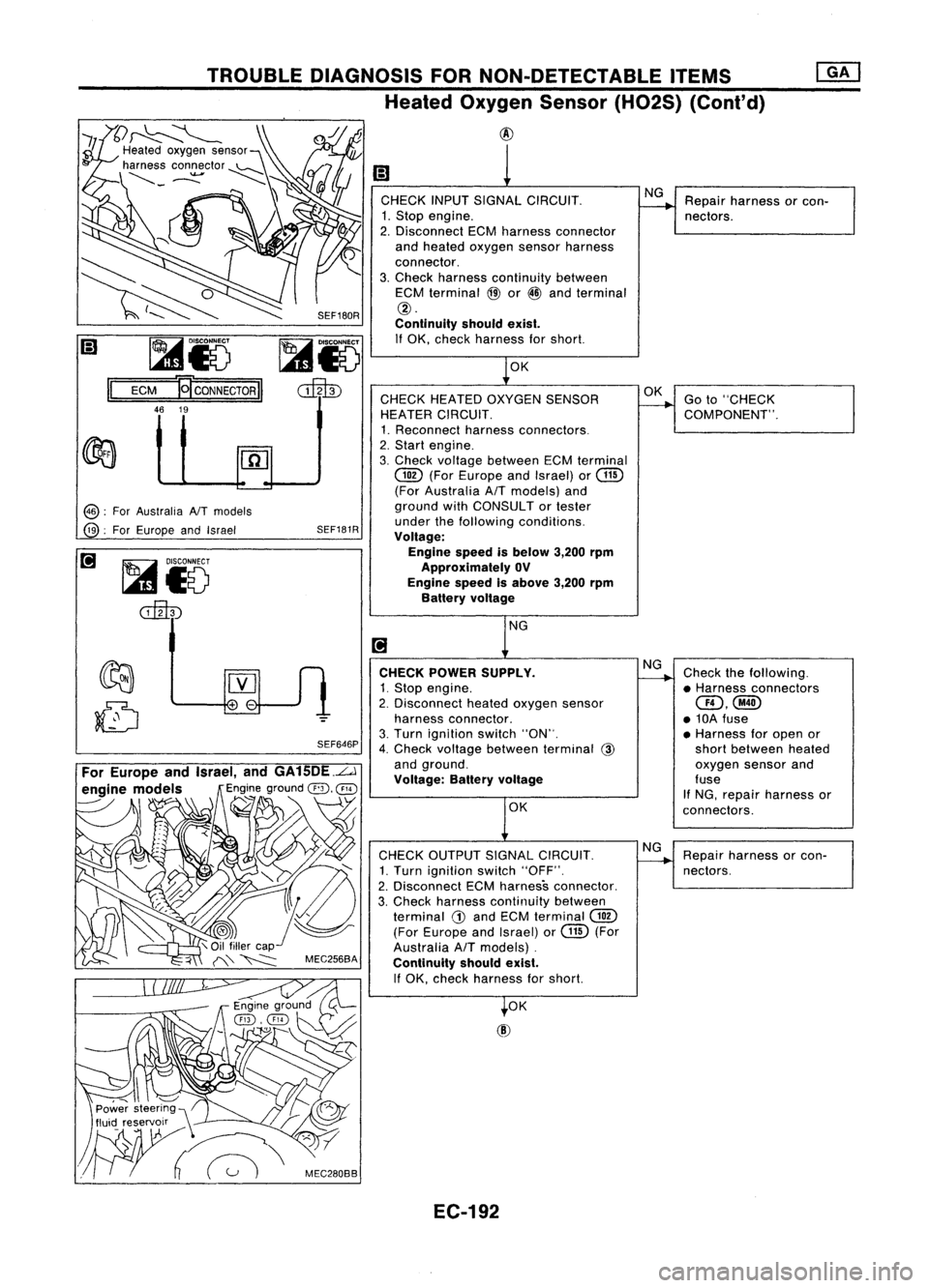
I;)
1
CHECK INPUTSIGNAL CIRCUIT. NG
Repair harness orcon-
1. Stop engine.
--.
nectors.
2. Disconnect ECMharness connector
and heated oxygen sensorharness
connector.
3. Check harness continuity between
ECM terminal
@
or
@
and terminal
@.
Continuity shouldexist.
If OK, check harness forshort.
1
0K
CHECK HEATED OXYGEN SENSOR OK
Goto"CHECK
HEATER CIRCUIT.
--.
COMPONENT".
1. Reconnect harnessconnectors.
2. Start engine.
3. Check voltage between ECMterminal
@
(ForEurope andIsrael) or
@
(For Australia AfTmodels) and
ground withCONSULTor tester
under thefollowing conditions.
Voltage:
Engine speedisbelow 3,200rpm
Approximately OV
Engine speedisabove 3,200rpm
Battery voltage
NG
[!J
CHECK POWER SUPPLY. NG
Check thefollowing.
1. Stop engine.
~
•Harness connectors
2. Disconnect heatedoxygen sensor
aD,@
harness connector. •10A fuse
3. Turn ignition switch"ON".
•Harness foropen or
4. Check voltage between terminal
@
shortbetween heated
and ground. oxygensensorand
Voltage: Batteryvoltage fuse
If NG, repair harness or
OK connectors.
CHECK OUTPUT SIGNALCIRCUIT. NG
Repair harness orcon-
1. Turn ignition switch"OFF".
-----...
nectors.
2. Disconnect ECMharness connector.
3, Check harness continuity between
terminal
G)
and ECM terminal
@
(For Europe andIsrael) orGill (For
Australia
AfT
models) .
Continuity shouldexist.
If OK, check harness forshort.
t
OK
SEF180R
SEF646P
SEF181R
~i5
cilltD
@:
ForAustralia NTmodels
@:
ForEurope andIsrael
TROUBLE
DIAGNOSIS FORNON-DETECTABLE ITEMS
Heated Oxygen Sensor(H02S) (Cont'd)
@
~
~
I;) ~i5
Il
ECM
'QcoNNECTORII
46 19
For Europe andIsrael, andGA15DE.L.J
engine models
Engineground
@,
@
----- \
~ ~
'1
\
.~
,~\ C/
Power steering",
fluid reservoir __\ ~
W~
:'C"",,
EC-192
Page 912 of 1701

TROUBLEDIAGNOSIS FORNON-DETECTABLE ITEMS
Heated Oxygen Sensor(H02S)(Cont'd)
@
Loosen andretighten engineground
screws.
OK
CHECK COMPONENT
(Heated oxygensensorheater).
Refer to"COMPONENT INSPECTION"
below.
OK
Disconnect andreconnect harnesscon-
ne~tors inthe circuit. Thenretest.
Trouble isnot fixed.
Check ECMpinterminals fordamage
or the connection ofECM harness con-
nector. Reconnect ECMharness con-
nector andretest.
Troubleisnot fixed.
Replace heatedoxygen sensor.
COMPONENT INSPECTION NG
Replace heatedoxygen
sensor.
•
DISCONNECT
I~J
00
SEF586Q
Heated
oxygen sensorheater
Check resistance betweenterminals
@
and
CD.
Resistance: 2.3-4.3Q at25°C (77°F)
Check continuity betweenterminals @and
CD,
@
and @.
Continuity shouldnotexist.
If NG, replace theheated oxygen sensor.
CAUTION:
• Discard anyoxygen sensorwhichhasbeen dropped from
a height ofmore than0.5m(19.7 in)onto ahard surface
such asaconcrete floor;useanew one.
EC-193
Page 915 of 1701
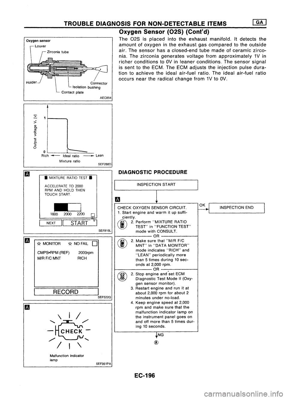
TROUBLEDIAGNOSIS FORNON-DETECTABLE ITEMS
Oxygen Sensor(02S)(Cont'd)
The 028 isplaced intotheexhaust manifold. Itdetects the
amount ofoxygen inthe exhaust gascompared tothe outside
air. The sensor hasaclosed-end tubemade ofceramic zirco-
nia. The zirconia generates voltagefromapproximately 1Vin
richer conditions toOV inleaner conditions. Thesensor signal
is sent tothe ECM. TheECM adjusts theinjection pulsedura-
tion toachieve theideal air-fuel ratio.Theideal air-fuel ratio
occurs neartheradical change from1VtoOV.
r
Connector
Isolation bushing
Contact plate
Oxygen
sensor
Louver
Zirconia tube
Holder AEC854
,'--
~
:>
Q)
OJ
.!!1
~ '5
0-
'5
o
o
Rich --- Idealratio
Mixture ratio_
Lean
SEF288D
m
•MIXTURE RATIOTEST.
ACCELERATE TO2CXXJ
RPM AND HOLD THEN
TOUCH START
~
1800 2CXXJ2200
~J
NEXT
II
START
SEF815L
m
1;{MONITOR 1;{NO FAIL
D
CMPS.RPM (REF)
2000rpm
MIR FICMNT RICH
RECORD \ I/
'~/'
- CHECK-
/
"-
I
I\
I
SEF522Q DIAGNOSTIC
PROCEDURE
INSPECTION START
CHECK OXYGEN SENSORCIRCUIT.
1. Start engine andwarm itup suffi-
ciently.
(F.i\
2.Perform "MIXTURE RATIO
~ TEST"in"FUNCTION TEST"
mode withCONSULT.
OR
(F.i\
2.Make surethat"M/R FIC
\..!!J
MNT"in"DATA MONITOR"
mode indicates "RICH"and
"LEAN" periodically more
than 5times during 10sec-
onds at2,000 rpm.
OR
~ 2.Stop engine and'set ECM
~ Diagnostic TestMode II(Oxy-
gen sensor monitor).
3. Restart engineandrunitat
about 2,000rpmforabout 2
minutes underno-load.
4. Keep engine speedat2,000
rpm andmake surethatthe
malfunction indicatorlampon
the instrument panelgoeson
and offmore than5times dur-
ing 10seconds.
NG
@
OK
INSPECTION END
Malfunction indicator
lamp SEF051PA
EC-196
Page 916 of 1701
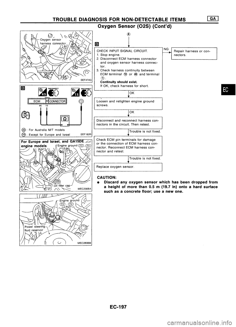
•
Repair
harness orcon-
nectors.
NG
OK
Loosen andretighten engineground
screws. CHECK
INPUTSIGNAL CIRCUIT.
1. Stop engine.
2. Disconnect ECMharness connector
and oxygen sensorharness connec-
tor.
3. Check harness continuity between
ECM terminal
@
or
@
and terminal
CD.
Continuity shouldexist.
If OK, check harness forshort.
~iV
@
TROUBLE
DIAGNOSIS FORNON-DETECTABLE ITEMS
Oxygen Sensor(02S)(Conl'd)
@
~Io
ECM
19'
CONNECTOR
II
46 19
II
OK
Disconnect andreconnect harnesscon-
nectors inthe circuit. Thenretest.
@:
ForAustralia M/Tmodels
@:
Except forEurope andIsrael
SEF182R
Trouble
isnot fixed.
Check ECMpinterminals fordamage
or the connection ofECM harness con-
nector. Reconnect ECMharness con-
nector andretest.
Troubleisnot fixed.
Replace oxygensensor.
CAUTION:
• Discard anyoxygen sensorwhichhasbeen dropped from
a height ofmore than0.5m(19.7 in)onto ahard surface
such asaconcrete floor;useanew one.
EC-197