1995 NISSAN ALMERA N15 check engine
[x] Cancel search: check enginePage 788 of 1701
•
2**
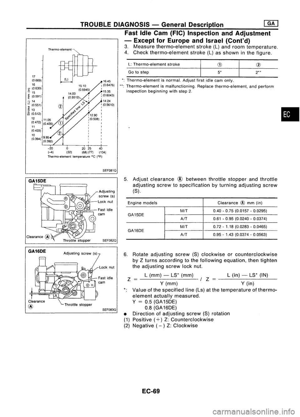
5*
Go
tostep
L:
Thermo-element stroke
*: Thermo-element isnormal. Adjustfirstidlecam only.
**: Thermo-element ismalfunctioning. Replacethermo-element, andperform
inspection beginningwithstep 2.
TROUBLE
DIAGNOSIS -General Description ~
Fast IdleCam (FIC) Inspection andAdjustment
- Except forEurope andIsrael (Cont'd)
3. Measure thermo-element stroke(L)and room temperature.
4. Check thermo-element stroke(L)asshown inthe figure.
Thermo-element
1645
1(0.6476)
I
15.35
: (06043)
'14.24
: (05610)
I
: 1290 :
I
(0.508)
I
I I
I I
I I
: I
I
r
I
r
r
I
I
I
-20 02025 40
HI (32)(68)(77) (104)
Thermo-element temperature°C(OF)
17
(0.669)
16
C (0630)
"" 15
~ (0591)
::J
14
-; (0.551)
t5
13
fJi
(0.512)
12 11.05
(0472) (0435)
11
(0433)
10
(0.394) 9.95
(0.392)
SEF0810
GA15DE
*.
GA16DE
Clearance
@ Adjusting
screw (s)
Lock nut
Fast idle
carn
SEF0820
SEF0830
5.
Adjust clearance
@
between throttlestopper andthrottle
adjusting screwtospecification byturning adjusting screw
(8).
Engine models Clearance
@
mm (in)
M/T 0.40-0.75 (0.0157 -0.0295)
GA15DE A/T0.61
-0.95 (0.0240 -0.0374)
M/T 0.72
-1.18 (0.0283 -0.0465)
GA16DE
A/T0.95
-1.43 (0.0374 -0.0563)
6. Rotate adjusting screw(8)clockwise orcounterclockwise
by Zturns according tothe following equation, thentighten
the adjusting screwlocknut.
L (mm) -L8* (mm) L(in) -L8* (IN)
Z =-------~ /Z =--------
Y
(mm)
Y
(in)
Value ofthe specified line(Ls) atthe temperature ofthermo-
element actuallymeasured.
Y
=
0.5 (GA 15DE)
0.8 (GA 16DE)
• Direction ofadjusting screw(8)rotation
(1) Positive (+)Z:Counterclockwise
(2) Negative (- )Z: Clockwise
EC-69
Page 793 of 1701
TROUBLEDIAGNOSES -General Description
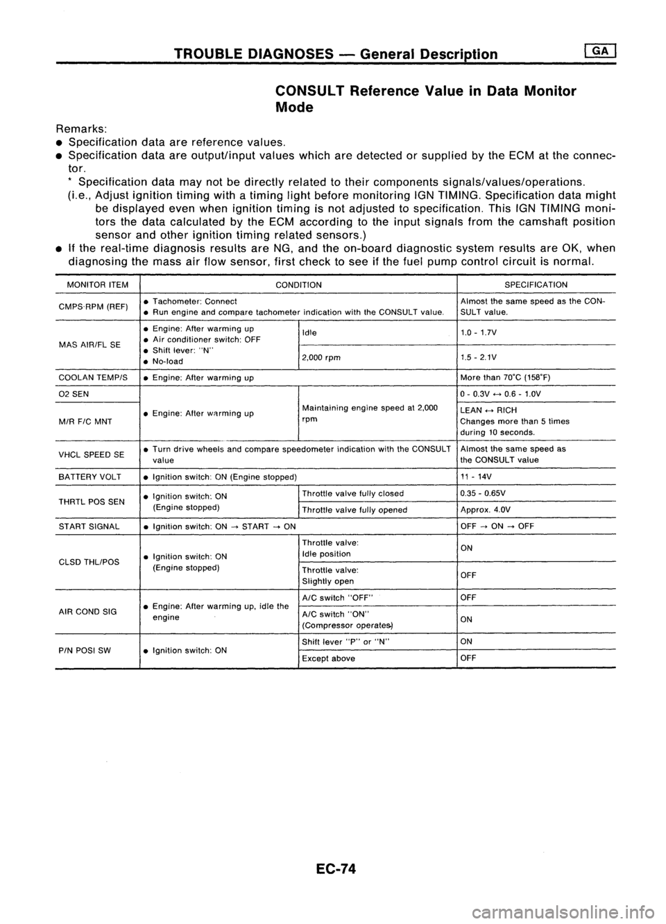
CONSULT ReferenceValueinData Monitor
Mode
Remarks:
• Specification dataarereference values.
• Specification dataareoutput/input valueswhicharedetected orsupplied bythe ECM atthe connec-
tor.
*
Specification datamaynotbedirectly relatedtotheir components signals/values/operations.
(Le., Adjust ignition timingwithatiming lightbefore monitoring IGNTIMING. Specification datamight
be displayed evenwhen ignition timingisnot adjusted tospecification. ThisIGNTIMING moni-
tors thedata calculated bythe ECM according tothe input signals fromthecamshaft position
sensor andother ignition timingrelated sensors.)
• Ifthe real-time diagnosis resultsareNG, and theon-board diagnostic systemresultsareOK, when
diagnosing themass airflow sensor, firstcheck tosee ifthe fuel pump control circuitisnormal.
MONITOR ITEM
CONDITION SPEC
IFICA TION
CMPS.RPM (REF)•
Tachometer: Connect Almostthesame speed asthe CON-
• Run engine andcompare tachometer indicationwiththeCONSULT value.SULT value.
• Engine: Afterwarming up
Idle 1.0
-1.7V
MAS AIRIFL SE •
Air conditioner switch:OFF
• Shift lever: "N"
• No-load 2,000
rpm 1.5
-2.1V
COOLAN TEMPIS •Engine: Afterwarming up More
than70°C (158°F)
02 SEN 0-
0.3V
<-+
0.6 -1.0V
• Engine: Afterwflrming up Maintaining
enginespeedat2,000
LEAN
<-+
RICH
MIR
FIC
MNT rpm
Changesmorethan5times
during 10seconds .
VHCL SPEED SE•
Turn drive wheels andcompare speedometer indicationwiththeCONSULT Almost
thesame speed as
value the
CONSULT value
SA TTERY VOLT •Ignition switch:ON(Engine stopped) 11
-14V
• Ignition switch:ON Throttle
valvefullyclosed 0.35
-0.65V
THRTL POSSEN
(Enginestopped)
Throttlevalvefullyopened Approx.
4.0V
ST ART SIGNAL •Ignition switch:ON
-->
START
-->
ON OFF
-->
ON
-->
OFF
Throttle valve:
ON
• Ignition switch:ON Idle
position
CLSD THLIPOS
(Enginestopped)
Throttlevalve:
OFF
Slightly open
AIC
switch "OFF" OFF
AIR COND SIG •
Engine: Afterwarming up,idle the
engine
AIC
switch "ON"
ON
(Compressor operate&)
Shift lever "P"or"N" ON
PIN POSI SW •Ignition switch:ON
Exceptabove OFF
EC-74
Page 798 of 1701
![NISSAN ALMERA N15 1995 Service Manual TROUBLEDIAGNOSES -General Description @K]
ECM Terminals andReference Value(Conl'd)
ECM INSPECTION TABLE-GA16DE forAustralia
Specification dataarereference valuesandaremeasured betweeneachterminal NISSAN ALMERA N15 1995 Service Manual TROUBLEDIAGNOSES -General Description @K]
ECM Terminals andReference Value(Conl'd)
ECM INSPECTION TABLE-GA16DE forAustralia
Specification dataarereference valuesandaremeasured betweeneachterminal](/manual-img/5/57349/w960_57349-797.png)
TROUBLEDIAGNOSES -General Description @K]
ECM Terminals andReference Value(Conl'd)
ECM INSPECTION TABLE-GA16DE forAustralia
Specification dataarereference valuesandaremeasured betweeneachterminal and
@
(ECCS ground).
TER- WIRE
MINAL ITEM
CONDITION DATA
NO. COLOR
[Efl9ineisrunning.
I
0.3-0.6V
L Idle speed
1
WIB
Ignitionsignal
I
Engine isrunning.
I
L Engine speedis2,000 rpm. Approximately
0.9V
2
GYIR
Ignition
check IEngine
isrunning.
I
Approximately12V
L Idle speed
3 LIB Tachometer [Engine
isrunning.
I
Approximately0.9V
L Idle speed
IEngine isrunning.
I
Ilgnition switch"OFF'.'
0-1V
4
WIG
ECCS
relay(Self-shut- L
For afew seconds afterturning ignition
off) switch
"OFF"
Ilgnition switch"OFF"
I
BATTERYVOLTAGE
L Afew seconds passedafterturning ignition
(11-14V)
switch "OFF"
Ilgnition switch"ON"
I
L For 5seconds afterturning ignition switch
0.07-0.20V
"ON"
8
BIP Fuel
pump relay I
Engine isrunning.
I
Ilgnition switch"ON"
I
BATTERYVOLTAGE
L More than5seconds afterturning ignition
(11-14V)
switch "ON"
10
BIW
ECCSground IEngine
isrunning.
I
Engineground
L Idle speed
IEngine isrunning.
I
BATTERYVOLTAGE
Cooling fanrelay ~Cooling fanisnot operating.
(11-14V).
13 LG
(Highspeed: For
AIT
Cooling
fanisoperating atlow speed.
models)
I
Engine isrunning.
I
L Cooling fanisoperating athigh speed. Approximately
OV
IEngine isrunning.
I
BATTERYVOLTAGE
Cooling fanrelay L
Cooling fanisnot operating. (11-14V)
14 LGIR
(Lowspeed)
I
Engine isrunning.
I
L_
Cooling fanisoperating. 0.07
-0.30V
I
Engine isrunning.
I
L Both
AIC
switch andblower switchare 0.08
-0.2V
15
Y
Air
conditioner relay "ON".
IEngine isrunning.
I
BATTERYVOLTAGE
LAIC switchis"OFF". (11
-14V)
EC-79
•
Page 802 of 1701
![NISSAN ALMERA N15 1995 Service Manual TROUBLEDIAGNOSES -General Description @K]
ECM Terminals andReference Value(Conl'd)
ECM INSPECTION TABLE-Except GA16DE forAustralia
Specification dataarereference valuesandaremeasured betweeneacht NISSAN ALMERA N15 1995 Service Manual TROUBLEDIAGNOSES -General Description @K]
ECM Terminals andReference Value(Conl'd)
ECM INSPECTION TABLE-Except GA16DE forAustralia
Specification dataarereference valuesandaremeasured betweeneacht](/manual-img/5/57349/w960_57349-801.png)
TROUBLEDIAGNOSES -General Description @K]
ECM Terminals andReference Value(Conl'd)
ECM INSPECTION TABLE-Except GA16DE forAustralia
Specification dataarereference valuesandaremeasured betweeneachterminal and
@
(ECCS ground).
TERMINAL WIRE
NO. COLOR ITEM
CONDITION DATA
IEngine isrunning.1
0.2-0.3V
L
Idle speed
1
WIB
Ignitionsignal
IEngineisru~
L
Engine speedis2,000 rpm. Approximately
0.7V
Tachometer IEngineisrunning.1
2 LIB
(Modelswithtachome-
L
Idle speed 0.7
-0.9V
ter)
3 GYIR
Ignitioncheck jEngine
isrunning.1
Approximately13V
L
Idle speed
Engine isrunning.'
I
Ignition switch"OFF"I
0-1V
ECCS relay(Self-shut-
L
For afew seconds afterturning ignition
4
WIG
off) switch
"OFF"
llgnition switch"OFF"I
BATTERYVOLTAGE
L
Afew seconds afterturning ignition
(11-14V)
switch "OFF"andthereafter
IEngine isrunning.1
BATTERYVOLTAGE
Cooling fanrelay (Low
L
Cooling fanisnot operating. (11-14V)
9 LGIR
speed) IEngineisrunning.1
L
Cooling fanisoperating. Approximately
OV
IEngine isrunning.1
BATTERYVOLTAGE
Cooling fanrelay (High
t
Cooling fanisnot operating.
(11-14V)
10 LG Cooling
fanisoperating atlow speed.
speed) IEngineisrunning.1
L
Cooling fanisoperating athigh speed. Approximately
OV
IEngine isrunning.1
L
Both
AIC
switch andblower fanswitch Approximately
OV
11 Yor
GAir
conditioner relay are
"ON".
IEngine isrunning.1
BATTERYVOLTAGE
LAIC
switchis"OFF". (11
-14V)
IEngine isrunning.1
BATTERYVOLTAGE
VTC solenoid valve
L
Idle speed (11
-14V)
12 YIR (GA
16DE engine mod-
IEngineisrunning.1
els except forEurope
and Israel)
L
Engine isracing quickly fromidleto4,000 Approximately
OV
rpm at1st position.
EC-83
•
Page 810 of 1701
TROUBLEDIAGNOSIS FORPOWER SUPPLY ~
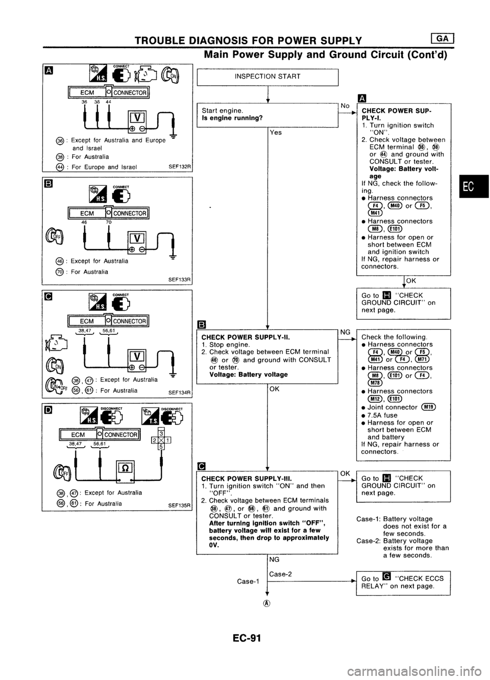
Main Power Supply andGround Circuit(Cont'd)
•
-!.OK
Go to
III
"CHECK
GROUND CIRCUIT" on
next page.
CHECK
POWER SUP-
PLY-I. 1. Turn ignition switch
"ON".
2. Check Yoltage between
ECM terminal
@,
@
or
@
and ground with
CONSULT ortester.
Voltage: Batteryvolt-
age
If NG, check thefollow-
ing .
• Harness connectors
GD,@orUD,
@
• Harness connectors
OO,@))
• Harness foropen or
short between ECM
and ignition switch
If NG, repair harness or
connectors.
Check thefollowing.
• Harness connectors
CID,
@O)ui)r
UD,
@or
F4,@
• Harness connectors
00, @))
or
Cill,
@
• Harness connectors
@,@))
• Joint connector
@
• 7.5A fuse
• Harness foropen or
short between ECM
and battery
If NG, repair harness or
connectors.
INSPECTION
START
Start engine.
Is engine running?
CHECK POWER SUPPLY-II.
1. Stop engine.
2. Check voltage between ECMterminal
~ or
@)
and ground withCONSULT
or tester.
Voltage: Batteryvoltage
OKYes
SEF134R
~i)
ECM
E[coNNECTORII
~;~~ ~i)
II
ECM
P!CONNECTORII
46 70
SEF133R
II
ECM
36 36
~85 ~r5
II
ECM
EJ
CONNECTOR
II
~53 1
~'.S~ ~
@:
Except forAustralia andEurope
-=
and Israel
@ :
For Australia
@ :
For Europe andIsrael SEF132R
@:
Except forAustralia
@ :
For Australia
~ @,@:
Except forAustralia
~FF
@,
@:
ForAustralia
@ ,
@: Except forAustralia
@ ,@:
ForAustralia
SEF135R
[!]
CHECK POWER SUPPLY-III.
1. Turn ignition switch"ON"andthen
"OFF".
2. Check Yoltage between ECMterminals
@,
@,
or
@,
i@
and ground with
CONSULT ortester.
After turning ignition switch"OFF",
battery voltage willexist forafew
seconds, thendrop toapproximately
av.
NG ~
Goto
III
"CHECK
GROUND CIRCUIT" on
next page.
Case-1: Batteryvoltage
does notexist fora
few seconds.
Case-2: Batteryvoltage
exists formore than
a few seconds.
Case-2
Case-1 Go
to[!1 "CHECK ECCS
RELAY" onnext page.
EC-91
Page 812 of 1701
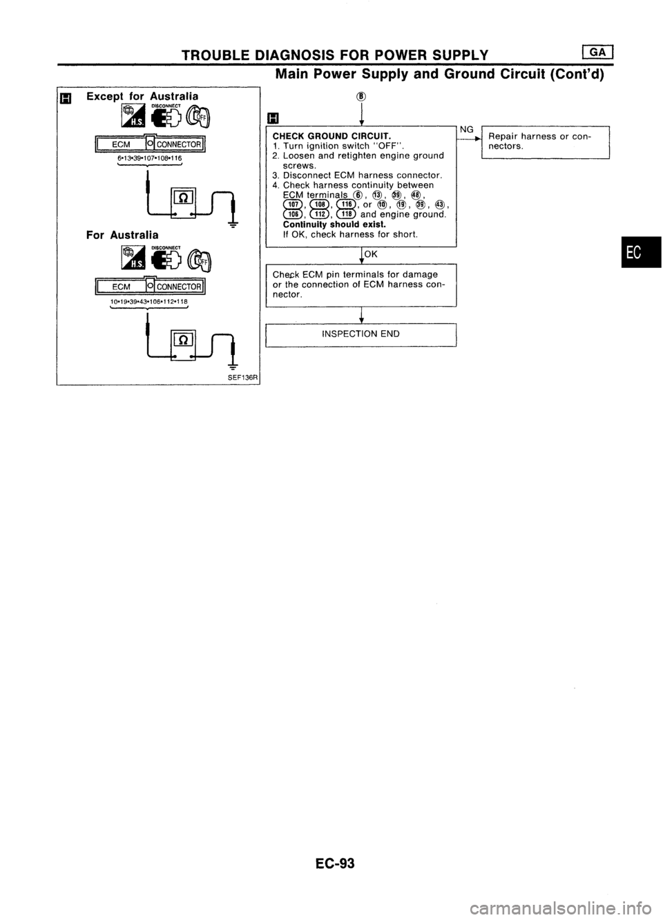
TROUBLEDIAGNOSIS FORPOWER SUPPLY
em
Main Power Supply andGround Circuit(Cont'd)
Except forAustralia
~i5~
II
ECM
B'
CONNECTOR
II
6-13-39-107-108-116
.
,
For Australia
~i5@a
II
ECM
B'
CONNECTOR
II
10-19-39-43-106-112-118
.
,
SEF136R CHECK
GROUND CIRCUIT.
1. Turn ignition switch"OFF".
2. Loosen andretighten engineground
screws.
3. Disconnect ECMharness connector.
4. Check harness continuity between
ECM terminals
@,
@,
@,@,
Gill, Gill,Gill,
or
@),
@,
@,
@,
GID, GID,
@
andengine ground.
Continuity shouldexist.
If OK, check harness forshort.
OK
Che~k ECMpinterminals fordamage
or the connection ofECM harness con-
nector.
INSPECTION END
EC-93
NG
Repair harness orcon-
nectors.
•
Page 813 of 1701
TROUBLEDIAGNOSIS FORDTC11
Light emitting
diode
Wave
forming circuit
Camshaft
PositionSensor(CMPS)
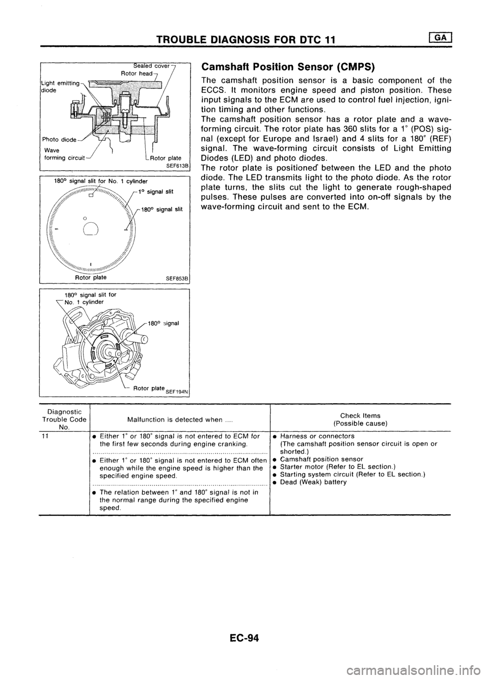
The camshaft positionsensorisabasic component ofthe
EGGS. Itmonitors enginespeedandpiston position. These
input signals tothe EGM areused tocontrol fuelinjection, igni-
tion timing andother functions.
The camshaft positionsensorhasarotor plate andawave-
forming circuit.Therotor plate has360slits fora1
0
(paS) sig-
nal (except forEurope andIsrael) and4slits fora180
0
(REF)
signal. Thewave-forming circuitconsists ofLight Emitting
Diodes (LED)andphoto diodes.
The rotor plate ispositioned' betweentheLED andthephoto
diode. TheLED transmits lighttothe photo diode. Asthe rotor
plate turns, theslits cutthe light togenerate rough-shaped
pulses. Thesepulses areconverted intoon-off signals bythe
wave-forming circuitandsent tothe EGM.
SEF653B
180
0
signal
Diagnostic
Trouble Code
No.
11
Malfunction
isdetected when....
• Either
l'
or 180' signal isnot entered toECM for
the first fewseconds duringengine cranking.
• Either
l'
or 180' signal isnot entered toECM often
enough whiletheengine speedishigher thanthe
specified enginespeed.
• The relation between
l'
and 180'signal isnot in
the normal rangeduring thespecified engine
speed.
EC-94
Check
Items
(Possible cause)
• Harness orconnectors
(The camshaft positionsensorcircuitisopen or
shorted.)
• Camshaft positionsensor
• Starter motor(Refer toEL section.)
• Starting systemcircuit(RefertoEL section.)
• Dead (Weak) battery
Page 818 of 1701
•
Repair harness orcon-
nectors.
Check
thefollowing.
• Harness foropen or
short between camshaft
position sensorand
ECCS relay
If NG, repair harness or
connectors .
NG
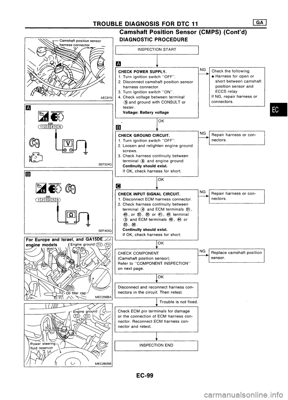
NG
CHECK
POWER SUPPLY.
1. Turn ignition switch"OFF".
2. Disconnect camshaftpositionsensor
harness connector.
3. Turn ignition switch"ON".
4. Check voltage between terminal
@
and ground withCONSULT or
tester.
Voltage: Batteryvoltage
CHECK GROUND CIRCUIT.
1. Turn ignition switch"OFF".
2. Loosen andretighten engineground
screws.
3. Check harness continuity between
terminal
@
and engine ground.
Continuity shouldexist.
If OK, check harness forshort.
AEC815
SEF524Q
TROUBLE
DIAGNOSIS FORDTC11 ~
Camshaft PositionSensor(CMPS) (Conl'd)
Camshaft positionsensor
DIAGNOSTIC PROCEDURE
harness connector
\ INSPECTIONSTART
Trouble isnot fixed.
~i5
@a
(i1'lmI51~ CHECK
INPUTSIGNAL CIRCUIT.
1. Disconnect ECMharness connector.
2. Check harness continuity between
terminal
@
and ECM terminals
@.
@),
or
@,
@
or
@, @
terminal
@
and ECM terminals
@),
@
or
@,@.
SEF463Q Continuityshouldexist.
If
OK, check harness forshort.
OK
CHECK COMPONENT
(Camshaft positionsensor).
Refer to"COMPONENT INSPECTION"
on next page.
OK
Disconnect andreconnect harnesscon-
nectors inthe circuit. Thenretest.
Check ECMpinterminals fordamage
or the connection ofECM harness con-
nector. Reconnect ECMharness con-
nector andretest.
INSPECTION END
NG
Repair
harness orcon-
nectors.
Replace camshaft position
sensor.
EC-99