Page 835 of 1701
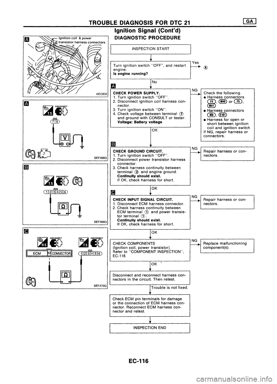
Repairharness orcon-
nectors.
Check
thefollowing.
• Harness connectors
QD,@orGD.
@
• Harness connectors
@.
• Harness foropen or
short between ignition
coil and ignition switch
If
NG, repair harness or
connectors.
Repair harness orcon-
nectors.
NG Yes
NG
NG
CHECK
GROUND CIRCUIT.
1. Turn ignition switch"OFF".
2. Disconnect powertransistor harness
connector.
3. Check harness continuity between
terminal
@
and engine ground.
Continuity shouldexist.
If OK, check harness forshort.
OK OK
INSPECTION
START
Turn ignition switch"OFF", andrestart
engine.
Is engine running?
No
CHECK POWER SUPPLV.
1. Turn ignition switch"OFF".
2. Disconnect ignitioncoilharness con-
nector.
3. Turn ignition switch"ON".
4. Check voltage between terminal
(J)
and ground withCONSULT ortester.
Voltage: Balteryvoltage
CHECK INPUTSIGNAL CIRCUIT.
1. Disconnect ECMharness connector.
2. Check harness continuity between
ECM terminal
G)
and power transis-
tor terminal
G).
Continuity shouldexist.
If
OK, check harness forshort.
AEC832
SEF468Q
TROUBLE
DIAGNOSIS FORDTC21
Ignition Signal(Cont'd)
DIAGNOSTIC PROCEDURE
SEF469Q
~15
@3
ill~
~85 ~85
II
ECM
~CONNECTORII
(tI2IffllsI6)
1 OK
CHECK COMPONENTS
(Ignition coil,power transistor).
Refer to"COMPONENT INSPECTION",
EC-118. NG
Replace malfunctioning
component(s).
OK •
Disconnect andreconnect harnesscon-
nectors inthe circuit. Thenretest.
SEF470Q
Troubleisnot fixed.
Check ECMpinterminals fordamage
or the connection ofECM harness con-
nector. Reconnect ECMharness con-
nector andretest.
INSPECTION END
EC-116
Page 836 of 1701
•
Repair
harness orcon-
nectors.
(;J
CHECK INPUTSIGNAL CIRCUIT. NG
1. Stop engine.
2. Disconnect ignitioncoilharness con-
nector.
3. Strip tapecovering resistoranddis-
connect theconnector.
4. Disconnect ECMharness connector.
5. Check harness continuity between
ignition coilterminal
@
and resistor
terminal
(!),
resistor terminal
@
and ECM terminal
@
or
@.
Continuity shouldexist.
If OK, check harness forshort.
TROUBLE
DIAGNOSIS FORDTC21
Ignition Signal(Cont'd)
@
~io
cffiJ
~i8
dIb
OK
~i5
1=1
=E=CM====!:E'
CONNECTOR
II
3
CHECK
COMPONENTS
(Resistor).
Refer to"COMPONENT INSPECTION"
on next page.
Disconnect andreconnect harnesscon-
nectors inthe circuit. Thenretest.
NG
Replace resistor.
Trouble isnot fixed.
@3)
CD:
For Australia
@ :Except forAustralia
SEF143R
Check
ECMpinterminals fordamage
or the connection ofECM harness con-
nector. Reconnect ECMharness con-
nector andretest.
INSPECTION END
EC-117
Page 838 of 1701
TROUBLEDIAGNOSIS FOROTC34
PIEZO-ELEMENT Malfunction isdetected when....
Diagnostic
Trouble Code
No. SEF598KKnock
Sensor (KS)
The knock sensor isattached tothe cylinder block.Itsenses
engine knocking usingapiezoelectric element.Aknocking
vibration fromthecylinder blockissensed asvibrational pres-
sure. Thispressure isconverted intoavoltage signalandsent
to the ECM.
CheckItems
(Possible Cause)
•
00
1)
2)
3)
34
•An excessively loworhigh voltage fromtheknock •Harness orconnectors
sensor isentered toECM. (Theknock sensor circuitisopen orshorted.)
• Knock sensor
DIAGNOSTIC TROUBLECODECONFIRMATION
PROCEDURE
rif\
1)Turn ignition switch"ON"andselect "DATA
\J!I)
MONITOR" modewithCONSULT.
2) Start engine andrunitfor atleast 5seconds atidle
speed.
---------- OR----------
Start engine andrunitfor atleast 5seconds atidle
speed.
Turn ignition switch"OFF", waitforatleast 5seconds
and then turn"ON".
Perform "Diagnostic TestMode II"(Self-diagnostic
results) withECM.
EC-119
Page 841 of 1701
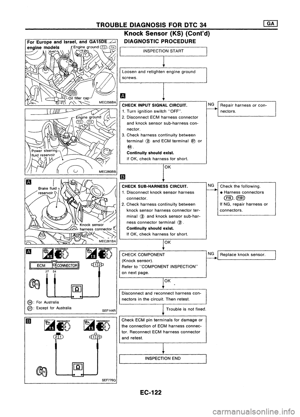
Replaceknocksensor.
NG
NG
Check thefollowing.
• Harness connectors
@,@
If NG, repair harness or
connectors.
r
OK
CHECK
SUB.HARNESS CIRCUIT.
1. Disconnect knocksensor harness
connector.
2. Check harness continuity between
knock sensor harness connector ter-
minal @and knock sensor sub-har-
ness connector terminal
@.
Continuity shouldexist.
If OK, check harness forshort.
CHECK COMPONENT
(Knock sensor).
Refer to"COMPONENT INSPECTION"
on next page.
Loosen
andretighten engineground
screws.
Fa
CHECK INPUTSIGNAL CIRCUIT. NG
Repair harness orcon-
1. Turn ignition switch"OFF".
--.
nectors.
2. Disconnect ECMharness connector
and knock sensor sub-harness con-
nector.
3. Check harness continuity between
terminal @and ECM terminal
@
or
@.
Continuity shouldexist.
If OK, check harness forshort.
TROUBLE
DIAGNOSIS FORDTC34
Knock Sensor (KS)(Conl'd)
DIAGNOSTIC PROCEDURE
For Europe andIsrael, andGA15DE.L..l
en~ine m\~~:e?, Is
Eng~eground
@'~@)
1 _
- \.Y
INSPECTIONSTART
J--
Fa
~i5
II
ECM
]9'CONNECTORII
27 54
,~\
C-/
Power steerin9\'
fluid reservoir /'\ /-:
.~~ :,c"",
OK
@:
ForAustralia
@:
Except forAustralia
SEF144RDisconnect
andreconnect harnesscon-
nectors inthe circuit. Thenretest.
Trouble isnot fixed.
Check ECMpinterminals fordamage or
the connection ofECM harness connec-
tor. Reconnect ECMharness connector
and retest.
INSPECTION END
SEF776Q EC.122
Page 843 of 1701
TROUBLEDIAGNOSIS FOROTC41
Intake AirTemperature Sensor(IATS)
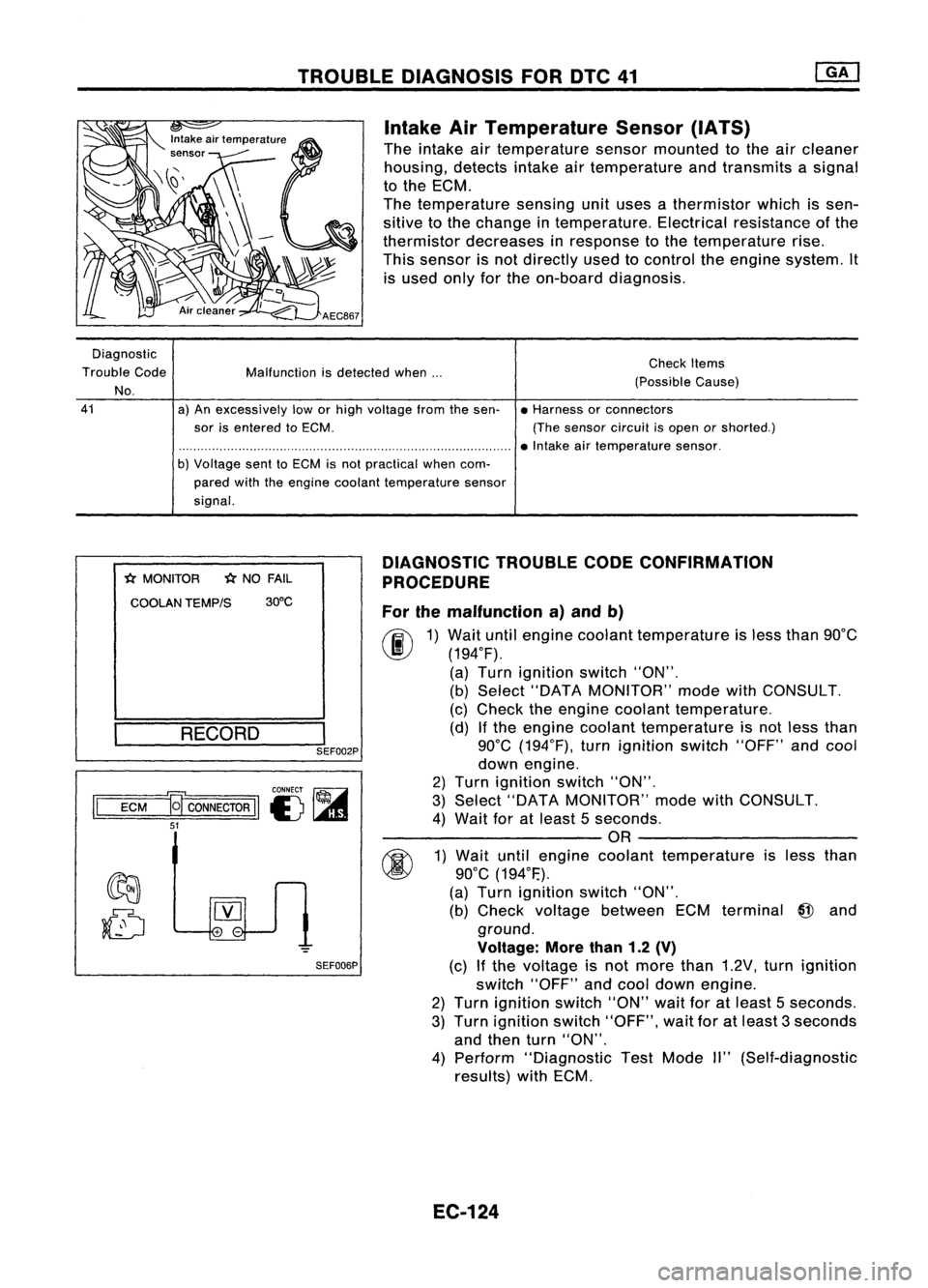
The intake airtemperature sensormounted tothe aircleaner
housing, detectsintakeairtemperature andtransmits asignal
to the ECM.
The temperature sensingunituses athermistor whichissen-
sitive tothe change intemperature. Electricalresistance ofthe
thermistor decreases inresponse tothe temperature rise.
This sensor isnot directly usedtocontrol theengine system. It
is used onlyforthe on-board diagnosis.
Diagnostic
Trouble Code
No.
41
Malfunction
isdetected when...
a) An excessively loworhigh voltage fromthesen-
sor isentered toECM.
b) Voltage senttoECM isnot practical whencom-
pared withtheengine coolant temperature sensor
signal. Check
Items
(Possible Cause)
• Harness orconnectors
(The sensor circuitisopen orshorted.)
• Intake airtemperature sensor.
*
MONITOR
*
NO FAIL
COOLAN TEMP/S 30°C
RECORD
I
SEF002P
CONNECT ~
II
ECM
a
CONNECTOR
II
I) ~
51
SEF006PDIAGNOSTIC
TROUBLECODECONFIRMATION
PROCEDURE
For themalfunction a)and b)
fF.I\
1)Wait untilengine coolant temperature isless than 90°C
~ (194°F).
(a) Turn ignition switch"ON".
(b) Select "DATA MONITOR" modewithCONSULT.
(c) Check theengine coolant temperature.
(d) Ifthe engine coolant temperature isnot less than
90°C (194°F), turnignition switch"OFF"andcool
down engine.
2) Turn ignition switch"ON".
3) Select "DATA MONITOR" modewithCONSULT.
4) Wait foratleast 5seconds.
---------OR ---------
~ 1)Wait untilengine coolant temperature isless than
~ 90°C(194°F.).
(a) Turn ignition switch"ON".
(b) Check voltage between ECMterminal
@
and
ground.
Voltage: Morethan1.2(V)
(c) Ifthe voltage isnot more than1.2V, turnignition
switch "OFF"andcool down engine.
2) Turn ignition switch"ON"waitforatleast 5seconds.
3) Turn ignition switch"OFF", waitforatleast 3seconds
and then turn"ON".
4) Perform "Diagnostic TestMode II"(Self-diagnostic
results) withECM.
EC-124
Page 845 of 1701
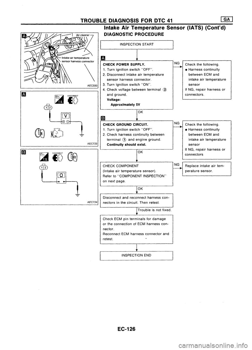
Checkthefollowing.
• Harness continuity
between ECMand
intake airtemperature
sensor
If NG, repair harness or
connectors.
NG
INSPECTION
START
CHECK POWER SUPPLY.
1. Turn ignition switch"OFF".
2. Disconnect intakeairtemperature
sensor harness connector.
3. Turn ignition switch"ON".
4. Check voltage between terminal @
and ground.
Voltage: Approximately SV
TROUBLE
DIAGNOSIS FORDTC41
rnJ
Intake AirTemperature Sensor(IATS)(Cont'd)
DIAGNOSTIC PROCEDURE
--
~
Intake airtemperature
'" '\ sensor harness connector
AEC550
~ DISCONNECT
ciili
10
AEC723
~i5 ~
dID
CHECK
GROUND CIRCUIT.
1. Turn ignition switch"OFF".
2. Check harness continuity between
terminal
G)
and engine ground.
Continuity shouldexist.
OK
CHECK COMPONENT
(Intake airtemperature sensor).
Refer to"COMPONENT INSPECTION"
on next page.
NG
NG
Check
thefollowing.
• Harness continuity
between ECMand
intake airtemperature
sensor
If NG, repair harness or
connectors
Replace intakeairtem-
perature sensor.
OK
Disconnect andreconnect harnesscon-
AEC724
nectorsinthe circuit. Thenretest.
Trouble isnot fixed.
Check ECMpinterminals fordamage
or the connection ofECM harness con-
nector.
Reconnect ECMharness connector and
retest.
INSPECTION END
EC-126
Page 850 of 1701
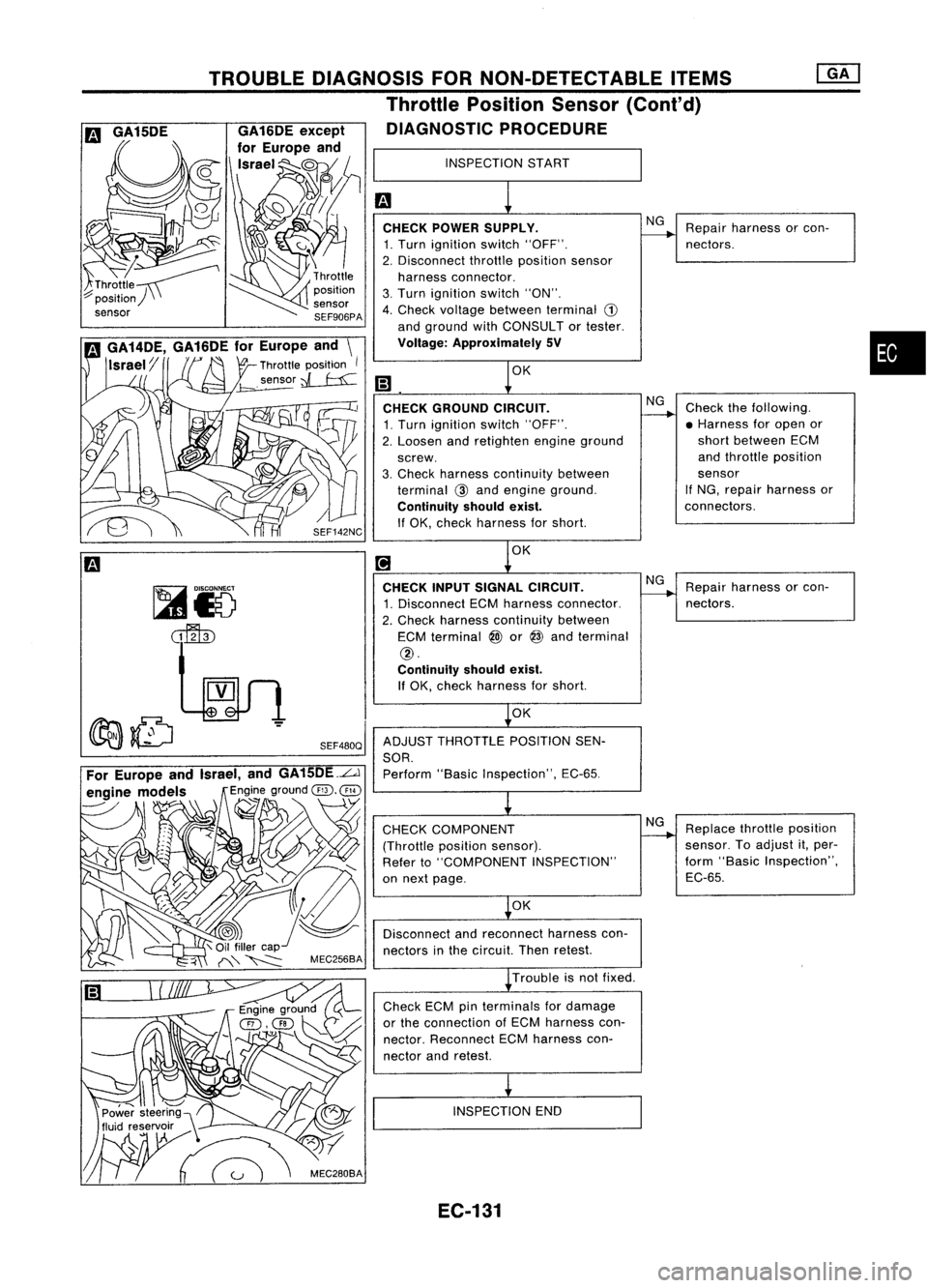
•
INSPECTION
START
m
1
CHECK POWER SUPPLY.
NG
Repair harness orcon-
------.
1. Turn ignition switch"OFF". nectors.
2. Disconnect throttleposition sensor
harness connector.
3. Turn ignition switch"ON".
4. Check voltage between terminal
CD
and ground withCONSULTor tester.
Voltage: Approximately SV
m
1
0K
CHECK GROUND CIRCUIT.
NG
Check thefollowing.
1. Turn ignition switch"OFF".
------.
•Harness foropen or
2. Loosen andretighten engineground short
between ECM
screw. and
throttle position
3. Check harness continuity between sensor
terminal
@
and engine ground. If
NG, repair harness or
Continuity shouldexist.
connectors.
If OK, check harness forshort.
[!J
1
0K
CHECK INPUTSIGNAL CIRCUIT.
NG
Repair harness orcon-
1. Disconnect ECMharness connector.
------.
nectors.
2. Check harness continuity between
ECM terminal
@)
or
@
and terminal
@.
Continuity shouldexist.
If OK, check harness forshort.
~OK
ADJUST THROTTLE POSITIONSEN-
SOR. Perform "BasicInspection", EC-65.
~
CHECK COMPONENT NG
Replace throttleposition
(Throttle positionsensor).
------.
sensor. Toadjust it,per-
Refer to"COMPONENT INSPECTION" form
"Basic Inspection",
on next page. EC-65.
~OK
Disconnect andreconnect harnesscon-
nectors inthe circuit. Thenretest.
~ Trouble isnot fixed.
Check ECMpinterminals fordamage
or the connection ofECM harness con-
nector. Reconnect ECMharness con-
nector andretest.
i
INSPECTION END
SEF480Q
TROUBLE
DIAGNOSIS FORNON-DETECTABLE ITEMS
Throttle Position Sensor(Cont'd)
DIAGNOSTIC PROCEDURE
,~\ C/
Power steering)\
~
m
GA15DE
EC-131
Page 859 of 1701
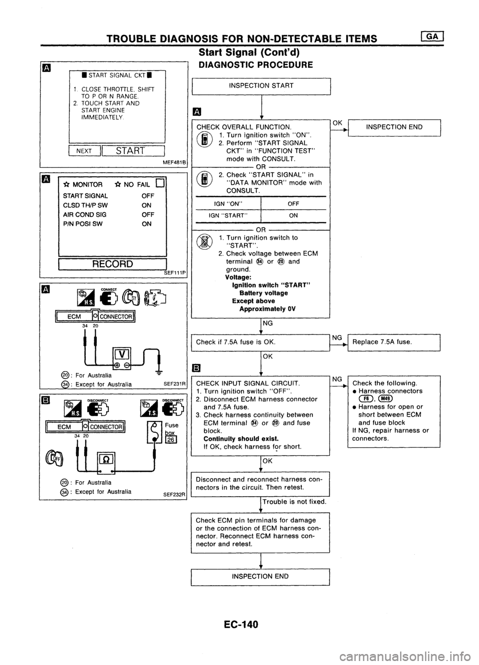
TROUBLEDIAGNOSIS FORNON-DETECTABLE ITEMS
Start Signal (Cont'd)
DIAGNOSTIC PROCEDURE
CHECK OVERALL FUNCTION.
00
1.
Turn ignition switch"ON".
I
II
2.
Perform "STARTSIGNAL
NEXT
START
CKT"
in"FUNCTION TEST"
MEF481B mode
withCONSULT.
OR
m
00
2.
Check "START SIGNAL" in
* MONITOR *
NO FAIL
0
"DATA
MONITOR" modewith
START SIGNAL CONSULT.
OFF
I
CLSDTH/PSW
ONIGN
"ON" OFF
AIR COND SIG OFF
IGN"START" ON
PIN POSI SW ON
II
•
START SIGNAL CKT.
CLOSE THROTTLE. SHIFT
TO POR NRANGE.
2. TOUCH STARTAND
START ENGINE
IMMEDIATELY.
~ __ RE_C_O_R_D_---,l
SEF111P
~I)~ID
ECM
B
CONNECTOR
II
34 20
INSPECTION
START
OR
1. Turn ignition switchto
"START".
2. Check voltage between ECM
terminal @or
@l
and
ground.
Voltage:
Ignition switch"START"
Battery voltage
Except above
Approximately OV
NG OK
INSPECTION END
II
@:
ForAustralia
34 :Except forAustralia
~Io
ECM
ET
CONNECTOR
II
34 20
@:
ForAustralia
@:
Except forAustralia SEF231R
SEF232R Check
if7.5A fuseisOK.
OK
CHECK INPUTSIGNAL CIRCUIT.
1. Turn ignition switch"OFF".
2. Disconnect ECMharness connector
and 7.5A fuse.
3. Check harness continuity between
ECM terminal @or
@l
and fuse
block.
Continuity shouldexist.
If OK, check harness f<;>rshort.
OK
Disconnect andreconnect harnesscon-
nectors inthe circuit. Thenretest.
Trouble isnot fixed.
Check ECMpinterminals fordamage
or the connection ofECM harness con-
nector. Reconnect ECMharness con-
nector andretest.
INSPECTION END
EC-140
NG
NG
Replace
7.5Afuse.
Check thefollowing.
• Harness connectors
(ID,@
• Harness foropen or
short between ECM
and fuse block
If NG, repair harness or
connectors.