1995 NISSAN ALMERA N15 check engine
[x] Cancel search: check enginePage 862 of 1701
•
INSPECTION END
Check thefollowing.
• Harness connectors
@,@or@,
@
• Harness connectors
@,CillD
• Harness foropen or
short between injector
and ignition switch
If NG, repair harness or
connectors.
OK
NG
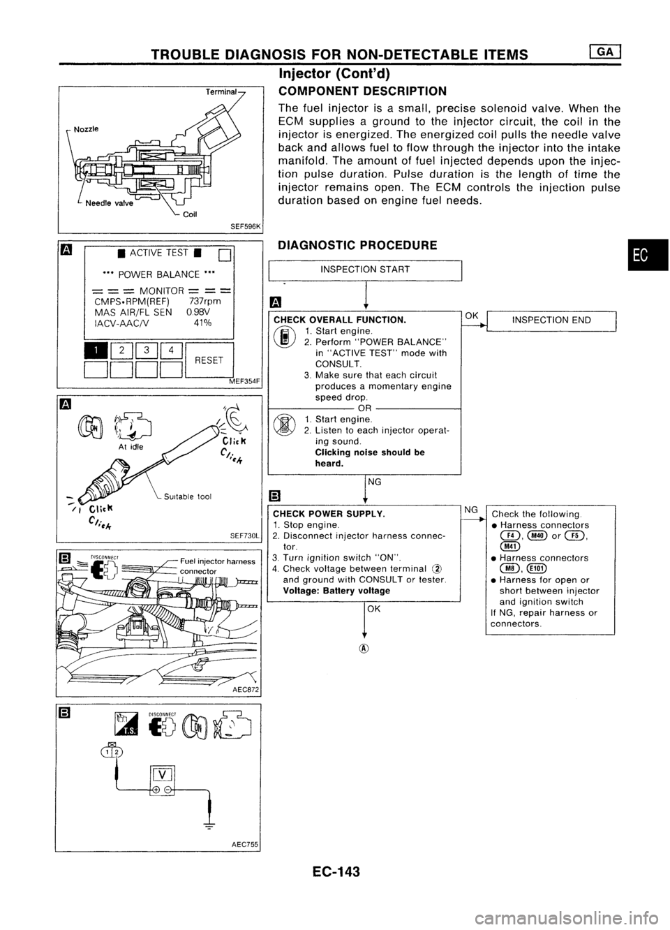
DIAGNOSTIC
PROCEDURE
INSPECTION START
CHECK OVERALL FUNCTION.
(F.I\
1.Start engine.
~ 2.Perform "POWER BALANCE"
in "ACTIVE TEST"modewith
CONSULT.
3. Make surethateach circuit
produces amomentary engine
speed drop.
OR
fff\
1.Start engine.
~ 2.Listen toeach injector operat-
ing sound.
Clicking noiseshould be
heard.
CHECK POWER SUPPLY.
1. Stop engine.
2. Disconnect injectorharness connec-
tor.
3. Turn ignition switch"ON".
4. Check voltage between terminal @
and ground withCONSULT ortester.
Voltage: Batteryvoltage
AEC872
SEF730L
/~~
Click
Ct.
'~.+
Fuel injector harness
connector
II
TROUBLE
DIAGNOSIS FORNON-DETECTABLE ITEMS
Injector (Cont'd)
COMPONENT DESCRIPTION
The fuel injector isasmall, precise solenoid valve.Whenthe
ECM supplies aground tothe injector circuit,thecoil
in
the
injector isenergized. Theenergized coilpulls theneedle valve
back andallows fueltoflow through theinjector intotheintake
manifold. Theamount offuel injected depends upontheinjec-
tion pulse duration. Pulseduration isthe length oftime the
injector remains open.TheECM controls theinjection pulse
duration basedonengine fuelneeds.
SEF596K
• ACTIVE TEST.
D
••• POWER BALANCE •••
= ==
MONITOR
=
==
CMPS.RPM(REF) 737rpm
MAS AIR/FL SEN098V
IACV-AAC/V 41%
110Q]Q]~
DDDDc:J
MEF354F
~7~
~ \)drJ
At idle
--
/ I
AEC755EC-143
Page 873 of 1701
Repairharness orcon-
nectors. INSPECTION
END
Check thefollowing.
• Harness connectors
QD,@orQD,
@
• 10A fuse
• Harness foropen or
short between IACV-AAC
valve andfuse
If NG, repair harness or
connectors.
NG OK
NG
OK
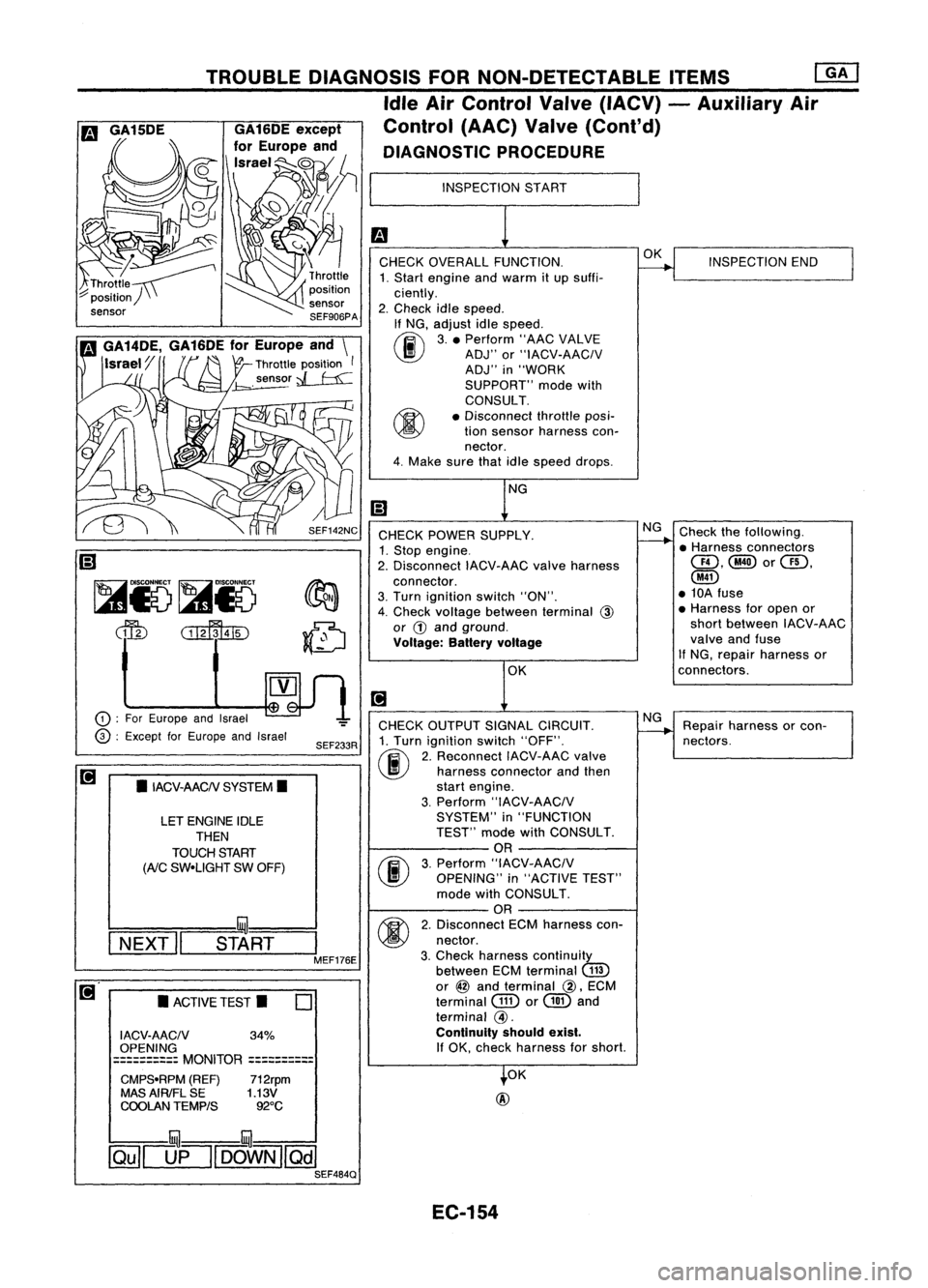
INSPECTION
START
CHECK OVERALL FUNCTION.
1. Start engine andwarm itup suffi-
ciently.
2. Check idlespeed.
If NG, adjust idlespeed.
~ 3.• Perform "AACVALVE
~ ADJ"or"IACV-AACIV
ADJ" in"WORK
SUPPORT" modewith
CONSULT.
• Disconnect throttleposi-
tion sensor harness con-
nector.
4. Make surethatidlespeed drops.
OK
@
CHECK
POWER SUPPLY.
1. Stop engine.
2. Disconnect IACV-AACvalveharness
connector.
3. Turn ignition switch"ON".
4. Check voltage between terminal
@
or
G)
and ground.
Voltage: Batteryvoltage
CHECK OUTPUT SIGNALCIRCUIT.
1. Turn ignition switch"OFF".
(ij\
2.Reconnect IACV-AACvalve
~ harnessconnector andthen
start engine.
3. Perform "IACV-AACIV
SYSTEM" in"FUNCTION
TEST" modewithCONSULT.
OR
(F.I\
3.Perform "IACV-AACIV
~ OPENING" in"ACTIVE TEST"
mode withCONSULT.
OR
M
2.Disconnect ECMharness con-
~ nectar.
3. Check harness continuity
between ECMterminal
(ill)
or
@
and terminal
@,
ECM
terminal
GID
or
@
and
terminal
@.
Continuity shouldexist.
If
OK, check harness forshort.
SEF233R
SEF142NC
o
•
ACTIVE TEST.
LET
ENGINE IDLE
THEN
TOUCH START
(AiC
SW-UGHT SWOFF)
•
IACV-AACN SYSTEM.
I ACV-AACN 34%
OPENING
==========
MONITOR
==========
CMPS-RPM (REF)712rpm
MAS AIRIFL SE 1.13V
COOLAN TEMPtS 92°C
TROUBLE
DIAGNOSIS FORNON-DETECTABLE ITEMS
ffiJ
Idle AirControl Valve(IACV) -Auxiliary Air
Control (AAC)Valve(Cont'd)
DIAGNOSTIC PROCEDURE
!:::=====mul===
I
NEXT" START
I
MEF176E
CD
:
For Europe andIsrael
@ :
Except forEurope andIsrael
~
Ii)
~i5~i5
dfu
CillffuID
illU--illU
~[]fl[OOWN][Qill SEF484Q
EC-154
Page 881 of 1701
Checkcooling fanlow
speed control circuit.
(Go to
I
PROCEDURE A
I.)
Check cooling fanhigh
speed control circuit.
(Go to
I
PROCEDURE B
I.)
NG
NG
OK
INSPECTION
START
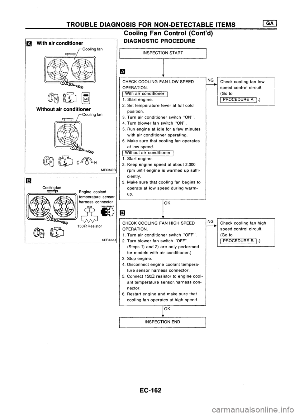
CHECK COOLING FANLOW SPEED
OPERATION.
I
With airconditioner
I
1. Start engine.
2. Set temperature leveratfull cold
position.
3. Turn airconditioner switch"ON".
4. Turn blower fanswitch "ON".
5. Run engine atidle forafew minutes
with airconditioner operating.
6. Make surethatcooling fanoperates
at low speed.
I
Without airconditioner
I
1. Start engine.
2. Keep engine speedatabout 2,000
rpm until engine iswarmed upsuffi-
ciently.
3. Make surethatcooling fanbegins to
operate atlow speed during warm-
up.
MEC340B
TROUBLE
DIAGNOSIS FORNON-DETECTABLE ITEMS
Cooling FanControl (Cant'd)
DIAGNOSTIC PROCEDURE
Cooling fan
Without
airconditioner
Coolingfan
Engine coolant
~ ~ ~a~~:;:t:a::;'~~'
~~ eN
lDoo
Q
CHECKCOOLING FANHIGH SPEED
150n
Resistor
~ ~ OPERATION.
~ ~ 1.Turn airconditioner switch"OFF".
SEF492Q
2.Turn blower fanswitch "OFF".
(Steps 1)and 2)are only performed
for models withairconditioner.)
3. Stop engine.
4. Disconnect enginecoolant tempera-
ture sensor harness connector.
5.
Connect
1500
resistor toengine cool-
ant temperature sensor.harness con-
nector.
6. Restart engineandmake surethat
cooling fanoperates athigh speed.
m
With airconditioner
Coolingfan
OK
INSPECTION END
EC-162
Page 882 of 1701
•
Check
thefollowing.
• 10A fuse
• 30A fusible link
• Harness foropen or
short between cooling
fan relay-1 andfuse
• Harness foropen or
short between cooling
fan relay-1 andbattery
If NG, repair harness or
connectors.
OK
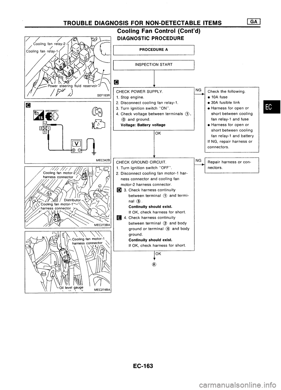
PROCEDURE
A
INSPECTION START
CHECK POWER SUPPLY. NG
1. Stop engine.
2. Disconnect coolingfanrelay-1.
3. Turn ignition switch"ON".
4. Check voltage between terminals
G),
@
and ground.
Voltage: Batteryvoltage
SEF193R
TROUBLE
DIAGNOSIS FORNON-DETECTABLE ITEMS
Cooling FanControl (Cont'd)
DIAGNOSTIC PROCEDURE
MEC342B
CHECKGROUND CIRCUIT.
1. Turn ignition switch"OFF".
2. Disconnect coolingfanmotor-1 har-
ness connector andcooling fan
motor-2 harness connector.
I!l
3.Check harness continuity
between terminal
CD
and termi-
nal
@.
Continuity shouldexist.
If OK, check harness forshort.
Ii
4.Check harness continuity
between terminal
@
and body
ground orterminal
@
and body
ground.
Continuity shouldexist.
If OK, check harness forshort.
OK
@
NG
Repair harness orcon-
nectors.
EC-163
Page 884 of 1701
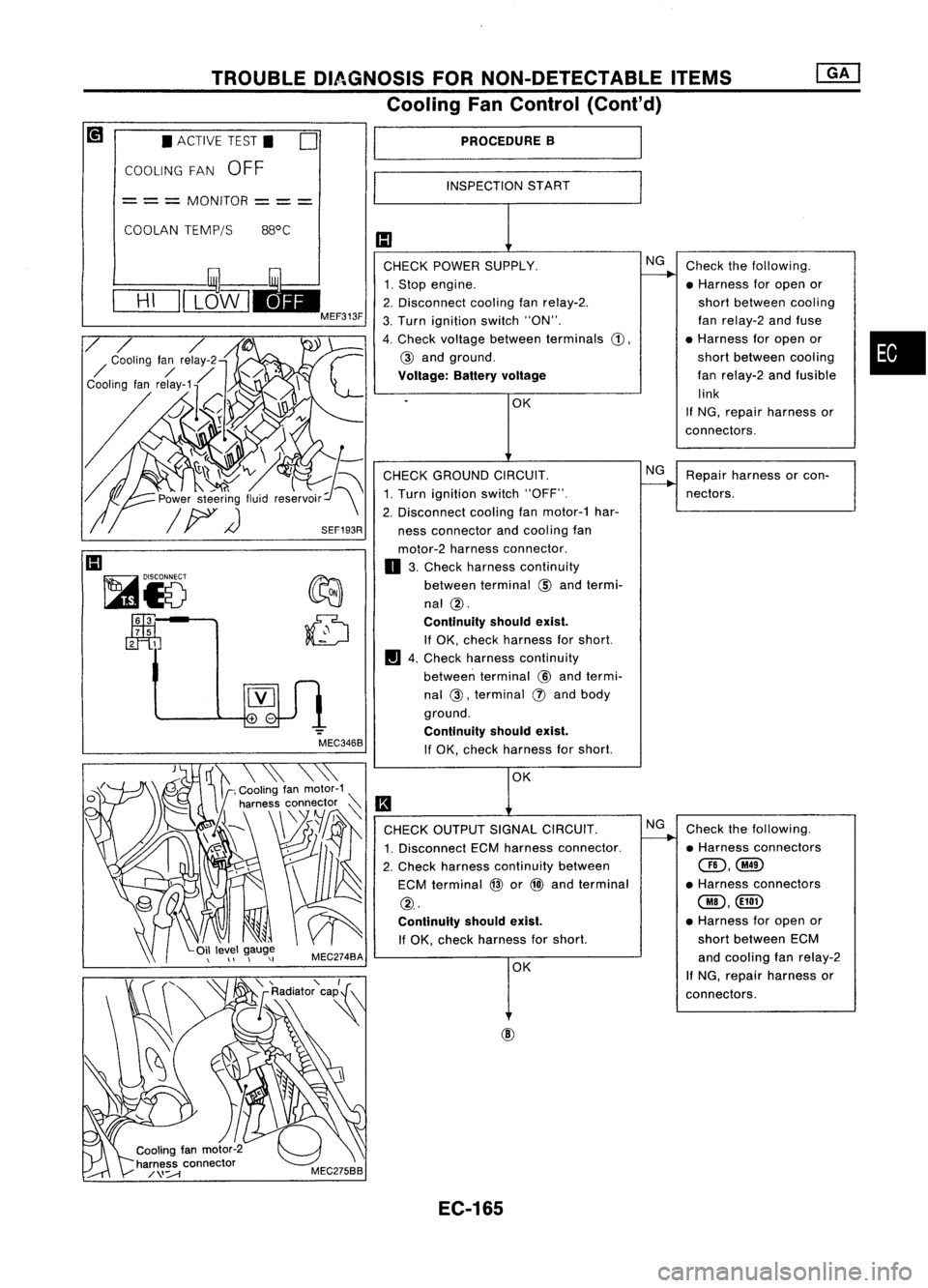
TROUBLEDIAGNOSIS FORNON-DETECTABLE ITEMS
Cooling FanControl (Cont'd)
•
PROCEDURE
B
INSPECTION START
1:1
CHECK POWER SUPPLY. NG
Check thefollowing.
----..
1. Stop engine. •Harness foropen or
2. Disconnect coolingfanrelay-2. short
between cooling
3. Turn ignition switch"ON". fan
relay-2 andfuse
4. Check voltage between terminals
G),
•
Harness foropen or
@
and ground. short
between cooling
Voltage: Batteryvoltage
fan
relay-2 andfusible
.
OK link
If
NG, repair harness or
connectors.
CHECK GROUND CIRCUIT. NG
Repair harness orcon-
1. Turn ignition switch"OFF".
----..
nectors.
2. Disconnect coolingfanmotor-1 har-
ness connector andcooling fan
motor-2 harness connector.
o
3.Check harness continuity
between terminal
@
and termi-
nal
@.
Continuity shouldexist.
If OK, check harness forshort.
II
4.Check harness continuity
between terminal
@
and termi-
nal
@,
terminal
(!)
and body
ground.
Continuity shouldexist.
If OK, check harness forshort.
OK
II
CHECK OUTPUT SIGNALCIRCUIT. NG
Check thefollowing.
1. Disconnect ECMharness connector.
----..
•Harness connectors
2. Check harness continuity between
@,@
ECM terminal
@
or
@l
and terminal •
Harness connectors
@.
@,@D
Continuity shouldexist.
•
Harness foropen or
If OK, check harness forshort. short
between ECM
OK and
cooling fanrelay-2
If
NG, repair harness or
connectors.
MEC346B
o
•
ACTIVE TEST.
COOLING FAN
OFF
COOLAN TEMP/S 88°C
=
= =
MONITOR
== =
1:1
~i5
~3
7 5
2 1
EC-165
Page 885 of 1701
TROUBLEDIAGNOSIS FORNON-DETECTABLE ITEMS
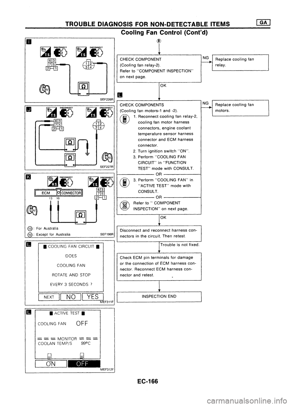
Cooling FanControl (Cont'd)
@
o
~i5
~-
m=m
CHECK
COMPONENT
(Cooling fanrelay-2).
Refer to"COMPONENT INSPECTION"
on next page.
NG
Replace coolingfan
relay.
OK
II
Replacecoolingfan
motors.
NG
OK
SEF226R
SEF227R
~i5
00
Jm1
3
7 5
2 1
CHECK
COMPONENTS
~ IDlsco~
(Coolingfanmotors-1 and-2).
I...s1
0~
1.Rec~nnect coolingfanrelay-2,
~ \J!}
coolingfanmotor harness
QW
connectors,enginecoolant
temperature sensorharness
connector andECM harness
connector.
2. Turn ignition switch"ON".
3. Perform "COOLING FAN
CIRCUIT" in"FUNCTION
TEST" modewithCONSULT.
OR
3. Perform "COOLING FAN"in
"ACTIVE TEST"modewith
CONSULT.
OR
~ Referto"COMPONENT
~ INSPECTION" onnext page.
~i5
:~
rn=m
~i5
ECM
El'CONNECTORII
13 10
II
@:
ForAustralia
@:
Except forAustralia SEF196R
Disconnect
andreconnect harnesscon-
nectors inthe circuit. Thenretest.
II
•COOLING FANCIRCUIT.
DOES
COOLING FAN
ROTATE ANDSTOP
Trouble
isnot fixed .
Check ECMpinterminals fordamage
or the connection ofECM harness con-
nector. Reconnect ECMharness con-
nector andretest.
EVERY 3SECONDS
7
NEXT
II
NO
II
YES
I
MEF311F
INSPECTION
END
II •
ACTIVE TEST.
COOLING FAN
OFF
=
= =
MONITOR
COOLAN TEMPjS
---
---
ggoC
CJ5_N_I~ MEF312F
EC-166
Page 890 of 1701

•
INSPECTION END
OK
The
power steering oilpressure switchisattached tothe power
steering high-pressure tubeanddetects apower steering load.
When apower steering loadisdetected,
it
signals theECM. The
ECM adjusts theIACV-AAC valvetoincrease theidle speed and
adjust forthe increased load.
INSPECTION START
OR
1. Start engine.
2. Check voltage between ECM
terminal
@
or
@
and ground.
Voltage: When steering wheelis
turned quickly.
Approximately OV
Except above
Approximately 5V
NG
DIAGNOSTIC
PROCEDURE
CHECK OVERALL FUNCTION.
fiii\
1.Turn ignition switch"ON".
~ 2.Perform "PW/STSIGNAL
CIRCUIT" in"FUNCTION
TEST" modewithCONSULT.
OR
(F.i\
1.Start engine.
~ 2.Check "PW/ST SIGNAL" in
"DATA MONITOR" modewith
CONSULT.
Steering isin neutral
position: OFF
Steering isturned:
ON
SEF591I
SEF235R
MEF023E
Power
steering oil___
pressure switch
-
~
to
TROUBLE
DIAGNOSIS FORNON-DETECTABLE ITEMS
@[]
Power Steering OilPressure Switch(Cont'd)
COMPONENT DESCRIPTION
RECORD
NEXT
II
START
•
PW/ST SIGNAL CIRCUIT.
HOLD STEERING WHEEL
IN AFULL
LOCKED
POSITION
THEN
TOUCH START
* MONITOR *NO FAIL
0
PW/ST SIGNAL OFF
@):
ForAustralia
@:
Except forAustralia
~i)~
II
ECM
Ef
CONNECTOR
II
43 25
EC-171
Page 891 of 1701
![NISSAN ALMERA N15 1995 Service Manual TROUBLEDIAGNOSIS FORNON-DETECTABLE ITEMS
@K]
Power Steering OilPressure Switch(Cont'd)
@:
ForAustralia
@:
Except forAustralia SEF176R
Repair
harness orcon-
nectors.
CHECK INPUTSIGNAL CIRCUIT. NISSAN ALMERA N15 1995 Service Manual TROUBLEDIAGNOSIS FORNON-DETECTABLE ITEMS
@K]
Power Steering OilPressure Switch(Cont'd)
@:
ForAustralia
@:
Except forAustralia SEF176R
Repair
harness orcon-
nectors.
CHECK INPUTSIGNAL CIRCUIT.](/manual-img/5/57349/w960_57349-890.png)
TROUBLEDIAGNOSIS FORNON-DETECTABLE ITEMS
@K]
Power Steering OilPressure Switch(Cont'd)
@:
ForAustralia
@:
Except forAustralia SEF176R
Repair
harness orcon-
nectors.
CHECK INPUTSIGNAL CIRCUIT. NG
Check thefollowing .
1. Disconnect ECMharness connector.
......---..
•Harness connectors
2. Check harness continuity between
aD,
(MID
ECM terminal
@
or
@
and terminal •
Harness connectors
G).
@,@or@,
Continuity shouldexist.
If
OK, check harness forshort. •
Harness foropen or
OK short
between ECMand
power steering oilpres-
sure switch
If NG, repair harness or
connectors.
CHECK COMPONENT NG
Replace powersteering
(Power steering oilpressure switch).
--...
oilpressure switch.
Refer to"COMPONENT INSPECTION"
below.
OK
Disconnect andreconnect harnesscon-
nectors inthe circuit. Thenretest.
Trouble isnot fixed.
Check ECMpinterminals fordamage or
the connection ofECM harness connec-
tor. Reconnect ECMharness connector
and retest.
@
1
CHECK GROUND CIRCUIT.
1. Turn ignition switch"OFF".
2. Disconnect powersteering oilpres-
sure switch harness connector.
3. Check harness continuity between
terminal
@
and engine ground.
Continuity shouldexist.
AEC760
IfOK, check harness forshort.
~i5
[i
c:ITb
~i5
ECM
Ef
CONNECTOR
II
43 25
II
INSPECTIONEND
Power steering oilpressure switch
1. Disconnect powersteering oilpressure switchharness con-
nector thenstart engine.
2. Check continuity betweenterminals
@.
[At
IV
ID
~ COMPONENT
INSPECTION
Conditions
Steering wheelisbeing turned
Steering wheelisnot being turned Continuity
Yes
No
AEC762
IfNG, replace powersteering oilpressure switch.
EC-172