Page 1019 of 1701
TROUBLEDIAGNOSIS FORDTC13 ~
Engine Coolant Temperature Sensor(ECTS)
(Cont'd)
COMPONENT INSPECTION
SEF152P Engine
coolant temperature sensor
Check resistance asshown inthe figure.
Temperature °C
(OF)
20 (68)
50 (122)
90 (194)
Resistance
kQ
2.1 -2.9
0.68 -1.00
0.236 -0.260
If NG, replace enginecoolant temperature sensor.
EC-300
Page 1038 of 1701
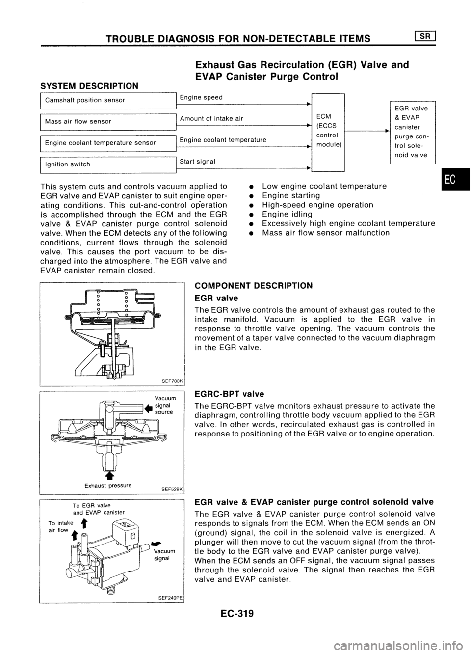
TROUBLEDIAGNOSIS FORNON-DETECTABLE ITEMS
Exhaust GasRecirculation (EGR)Valveand
EVAP Canister PurgeControl
SYSTEM DESCRIPTION
I
Camshaft positionsensor
I
Engine speed
EGRvalve
I
Mass
airflow sensor
I
Amount ofintake air ECM
&
EVAP
(ECCS canister
I
~Engine
coolanttemperature control
purgecon-
Engine coolant temperature sensor
module)trolsole-
I
noid
valve
Ignition switch
I
Start signal
I
This system cutsandcontrols vacuumappliedto
EGR valve andEVAP canister tosuit engine oper-
ating conditions. Thiscut-and-control operation
is accomplished throughtheECM andtheEGR
valve
&
EVAP canister purgecontrol solenoid
valve. WhentheECM detects anyofthe following
conditions, currentflowsthrough thesolenoid
valve. Thiscauses theport vacuum tobe dis-
charged intotheatmosphere. TheEGR valve and
EVAP canister remainclosed.
•
•
•
•
•
•
Low
engine coolant temperature
Engine starting
High-speed engineoperation
Engine idling
Excessively highengine coolant temperature
Mass airflow sensor malfunction
•
Exhaust pressure COMPONENT
DESCRIPTION
EGR valve
The EGR valve controls theamount ofexhaust gasrouted tothe
intake manifold. Vacuumisapplied tothe EGR valve in
response tothrottle valveopening. Thevacuum controls the
movement ofataper valve connected tothe vacuum diaphragm
in the EGR valve.
SEF783K EGRC-BPT valve
The EGRC-BPT valvemonitors exhaustpressure toactivate the
diaphragm, controllingthrottlebodyvacuum appliedtothe EGR
valve. Inother words, recirculated exhaustgasiscontrolled in
response topositioning ofthe EGR valve ortoengine operation.
SEF529K
~ Vacuumsignal
SEF240PE EGR
valve
&
EVAP canister purgecontrol solenoid valve
The EGR valve
&
EVAP canister purgecontrol solenoid valve
responds tosignals fromtheECM. When theECM sends anON
(ground) signal,thecoil inthe solenoid valveisenergized. A
plunger willthen move tocut the vacuum signal(fromthethrot-
tle body tothe EGR valve andEVAP canister purgevalve).
When theECM sends anOFF signal, thevacuum signalpasses
through thesolenoid valve.Thesignal thenreaches theEGR
valve andEVAP canister.
EC-319
Page 1054 of 1701
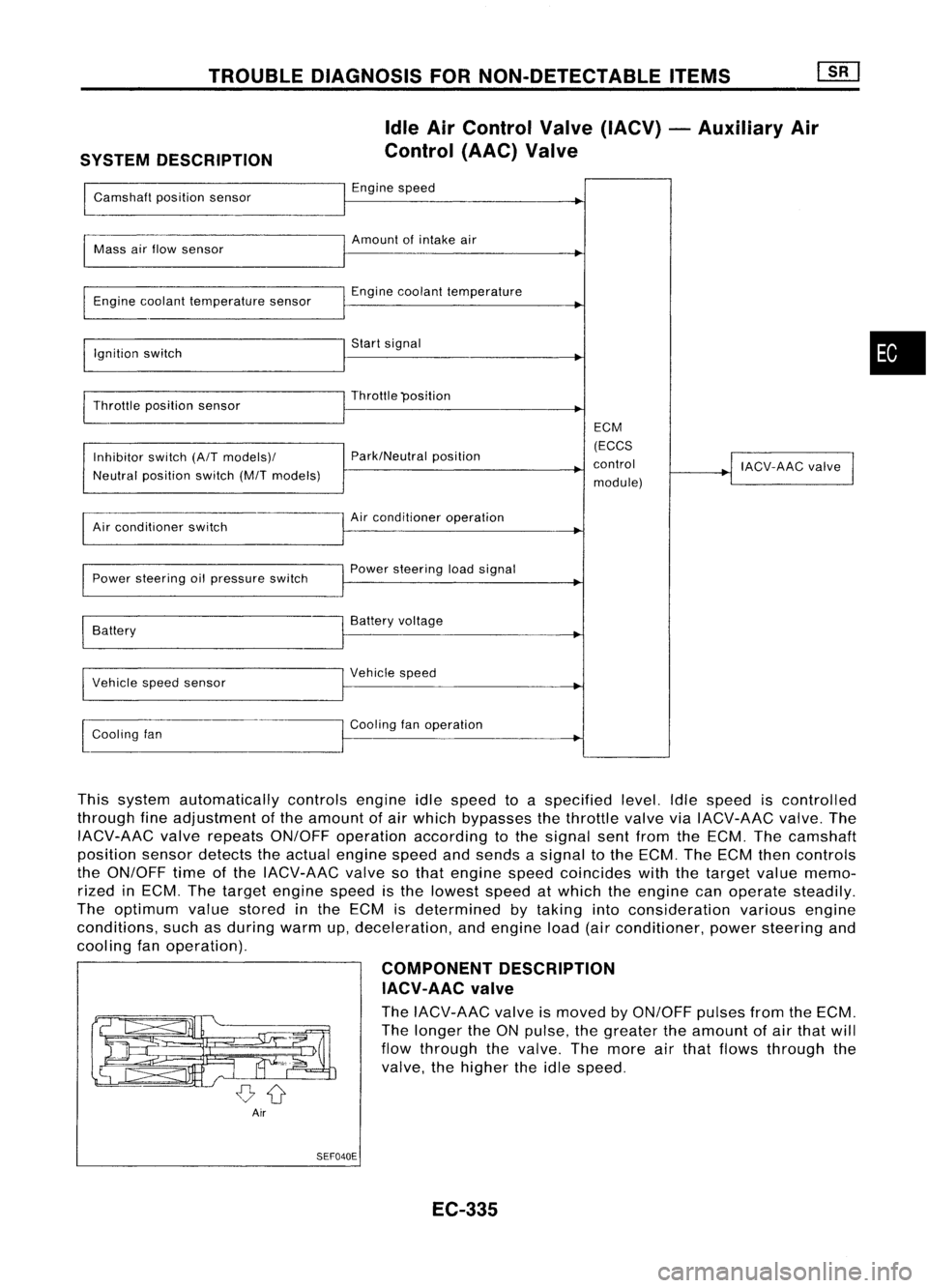
TROUBLEDIAGNOSIS FORNON-DETECTABLE ITEMS
SYSTEM DESCRIPTION Idle
AirControl Valve(IACV) -Auxiliary Air
Control (AAC)Valve
Camshaft positionsensor Engine
speed
~
I
Amount ofintake air
Mass airflow sensor
I
Engine coolant temperature sensor Engine
coolant temperature
I
Ignition switch Start
signal
I
Throttle position sensor Throttle
"position
I
ECM
Inhibitor switch(A/Tmodels)/ Park/Neutral
position (ECCS
control
!
IACV-AAC valve
I
Neutral position switch(M/Tmodels)
module)
Air conditioner switch Air
conditioner operation
Power steering oilpressure switch Power
steering loadsignal
I
Battery Battery
voltage
Vehicle speedsensor Vehicle
speed
I
l
Cooling fan Cooling
fanoperation
I
This system automatically controlsengineidlespeed toaspecified level.Idlespeed iscontrolled
through fineadjustment ofthe amount ofair which bypasses thethrottle valveviaIACV-AAC valve.The
IACV-AAC valverepeats ON/OFF operation according tothe signal sentfrom theECM. Thecamshaft
position sensordetects theactual engine speedandsends asignal tothe ECM. TheECM thencontrols
the ON/OFF timeofthe IACV-AAC valvesothat engine speedcoincides withthetarget valuememo-
rized inECM. Thetarget engine speedisthe lowest speedatwhich theengine canoperate steadily.
The optimum valuestored inthe ECM isdetermined bytaking intoconsideration variousengine
conditions, suchasduring warmup,deceleration, andengine load(airconditioner, powersteering and
cooling fanoperation).
COMPONENTDESCRIPTION
IACV-AAC valve
The IACV-AAC valveismoved byON/OFF pulsesfromtheECM.
The longer theONpulse, thegreater theamount ofair that will
flow through thevalve. Themore airthat flows through the
valve, thehigher theidle speed.
Air SEF040E
EC-335
•
Page 1062 of 1701
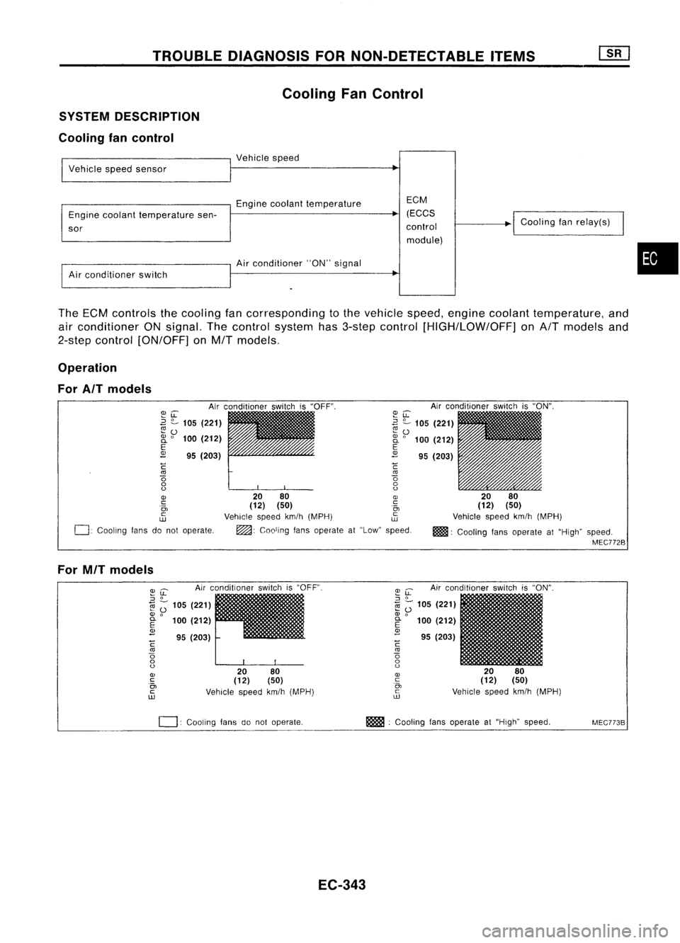
TROUBLEDIAGNOSIS FORNON-DETECTABLE ITEMS
Cooling FanControl
SYSTEM DESCRIPTION
Cooling fancontrol
I
Vehicle speedsensor
I
Vehicle speed
Engine coolant temperature EGM
Engine coolant temperature sen- (EGGS
~
sor control
module)
I
Air conditioner switch
I
Air conditio~er "ON"signal
I
Goaling fanrelay(s)
•
The ECM controls thecooling fancorresponding tothe vehicle speed,engine coolant temperature, and
air conditioner ONsignal. Thecontrol system has3-step control [HIGH/LOW/OFF] onA/T models and
2-step control [ON/OFF] onM/T models.
Operation
For AIT models
Airconditioner switchis"ON".
20 80
(12) (50)
Vehicle speedkm/h(MPH)
m!lll:
Cooling fansoperate at"High" speed.
MEC772B
~u:
~ ?-
105 (221)
~ 0
2i
0
100 (212)
E
2
95(203)
C
'"
o
o
o
20 80
OJ
(12) (50) .~
Vehicle speedkm/h(MPH) ~
~: Cooling fansoperate at"Low" speed.
~LL
.3
?-
105 (221)
~o
2i
0
100 (212)
E
2
95(203)
C
'"
o
o
o
OJ
c:
.0,
c
w
0:
Cooling fansdonot operate.
For MIT models
Airconditioner switchis"OFF".
2080
(12) (50)
Vehicle speedkm/h(MPH)
~
u:
Airconditioner switchis"ON".
::J
0
1il
Z;
105 (221)
OJ
0
E
100(212)
OJ
- 95(203)
C
'"
o
o
o
OJ
c
0,
c
ill
I
20 80
(12) (50)
Vehicle speedkm/h(MPH)
~u:
::J
0
1il ;-
105 (221)
OJ
0
~ 100(212)
<1>
- 95(203)
C
'"
o
o
o
OJ
c
.0,
c
ill
0:
COOling fansdonot operate. m
:Cooling fansoperate at"High" speed.
MEC773B
EC-343
Page 1068 of 1701
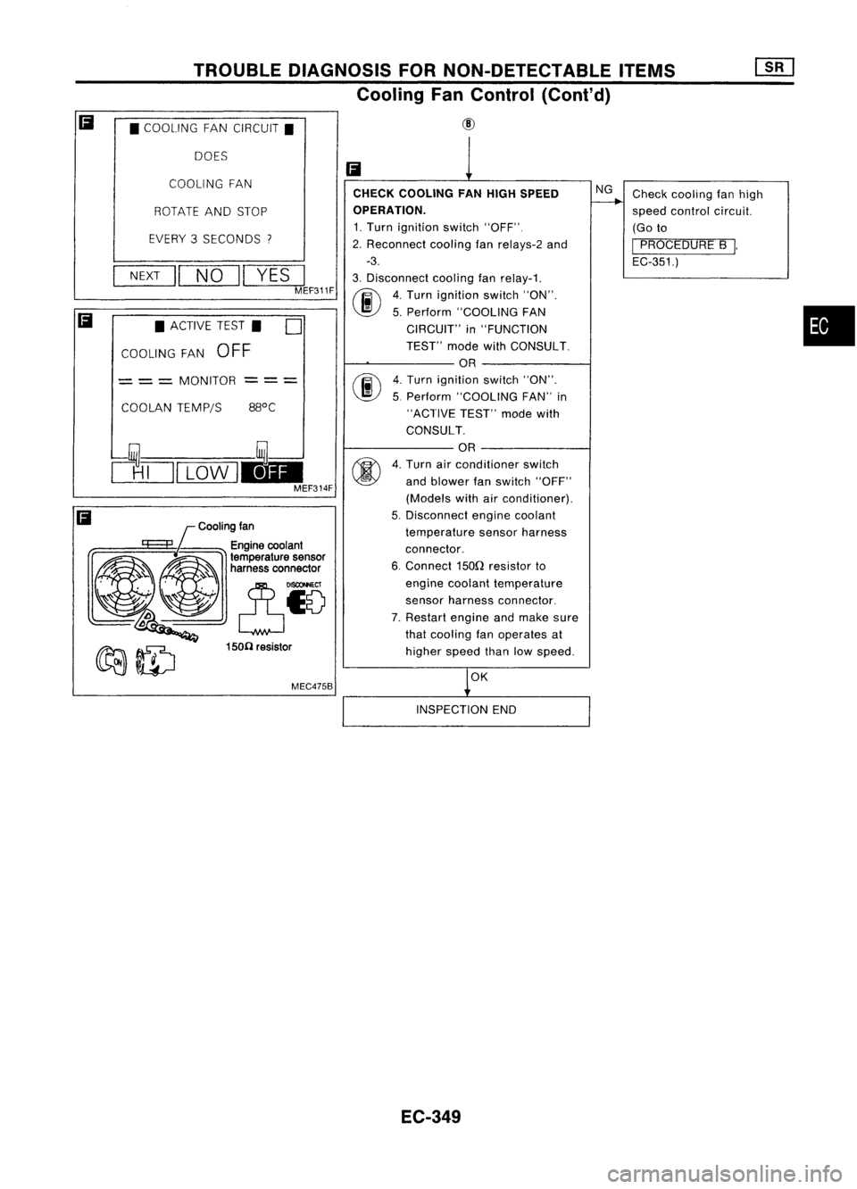
TROUBLEDIAGNOSIS FORNON-DETECTABLE ITEMS
Cooling FanControl (Cont'd)
• COOLING FANCIRCUIT.
DOES
Cooling fan
MEC475B
COOLING
FAN
•
Check
cooling fanhigh
speed control circuit.
(Go to
I
PROCEDURE B
I.
EC-351.)
NG
OK
CHECK
COOLING FANHIGH SPEED
OPERATION.
1. Turn ignition switch"OFF".
2. Reconnect coolingfanrelays-2 and
-3.
3. Disconnect coolingfanrelay-1.
(ij\
4.Turn ignition switch"ON".
~ 5.Perform "COOLING FAN
CIRCUIT" in"FUNCTION
TEST" modewithCONSULT.
OR
fiii\
4.Turn ignition switch"ON".
~ 5.Perform "COOLING FAN"in
"ACTIVE TEST"modewith
CONSULT.
OR
4. Turn airconditioner switch
and blower fanswitch "OFF"
(Models withairconditioner).
5. Disconnect enginecoolant
temperature sensorharness
connector.
6. Connect 150Qresistor to
engine coolant temperature
sensor harness connector.
7. Restart engineandmake sure
that cooling fanoperates at
higher speedthanlowspeed.
Ii
--- ---
150(1 resistor
ROTATE
ANDSTOP
EVERY 3SECONDS
"I
NEXT
II
NO
II
YES
I
MEF311F
COOLAN TEMP/S
•
ACTIVE TEST. D
COOLING FAN
OFF
= ==
MONITOR
clTJI
LOW
1.1-
MEF314F
Ii
Ii
INSPECTIONEND
EC-349
Page 1087 of 1701
TROUBLEDIAGNOSIS FORNON-DETECTABLE ITEMS~
Torque Converter ClutchSolenoid Valve(Cont'd)
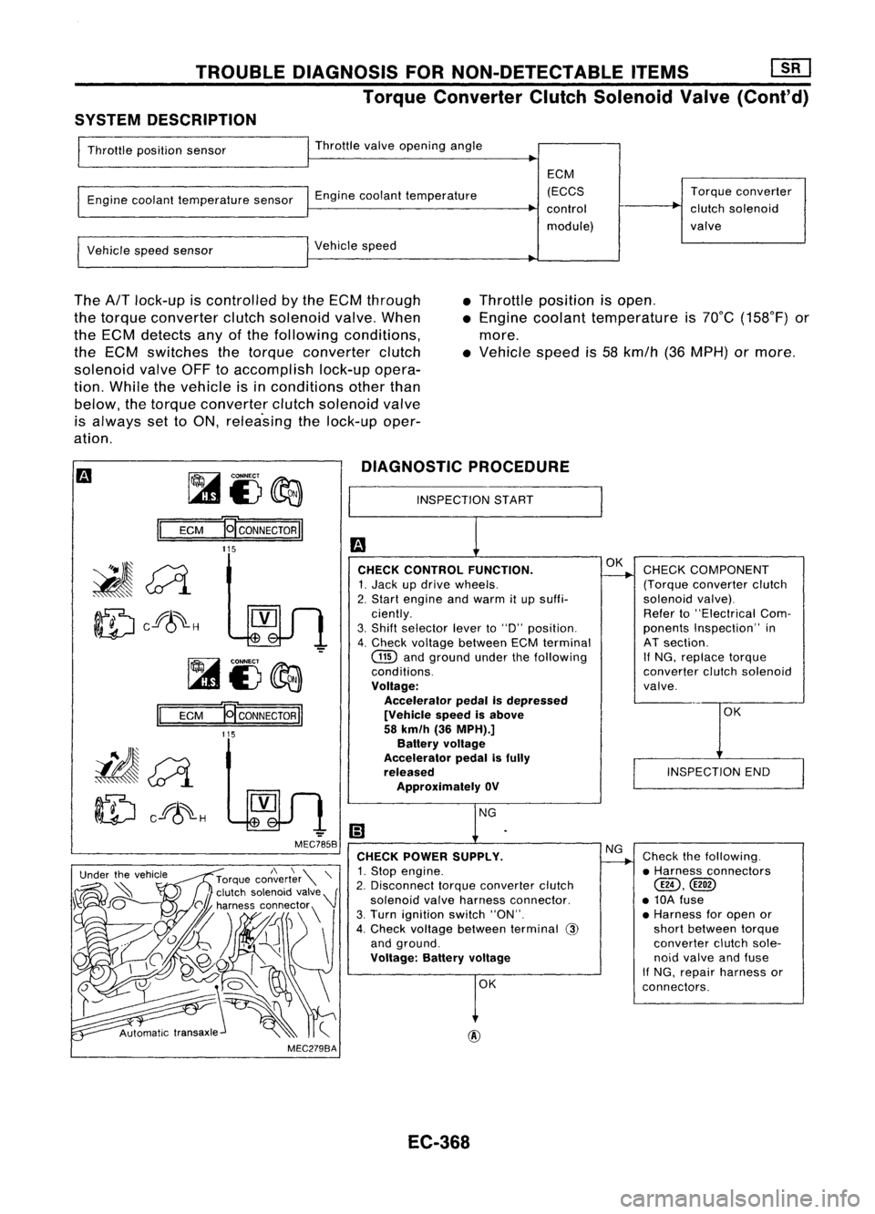
SYSTEM DESCRIPTION
Throttle position sensor Throttle
valveopening angle
Engine coolant temperature sensorEnginecoolant temperature ECM
(ECCS
control
module) Torque
converter
clutch solenoid
valve
Vehicle speedsensor Vehicle
speed
The
AfT
lock-up iscontrolled bythe ECM through
the torque converter clutchsolenoid valve.When
the ECM detects anyofthe following conditions,
the ECM switches thetorque converter clutch
solenoid valveOFFtoaccomplish lock-upopera-
tion. While thevehicle isinconditions otherthan
below, thetorque converter clutchsolenoid valve
is always settoON, relea'sing thelock-up oper-
ation. •
Throttle position isopen .
• Engine coolant temperature is70°C (158°F) or
more .
• Vehicle speedis58 kmfh (36MPH) ormore.
~i3~
II
ECM
E[CONNECTORII
DIAGNOSTIC
PROCEDURE
INSPECTION START
115
OK
INSPECTION END
CHECK
COMPONENT
(Torque converter clutch
solenoid valve).
Refer to"Electrical Com-
ponents Inspection" in
AT section.
If
NG, replace torque
converter clutchsolenoid
valve.
Check thefollowing.
• Harness connectors
@,
• 10A fuse
• Harness foropen or
short between torque
converter clutchsole-
noid valve andfuse
If NG, repair harness or
connectors.
NG
OK
OK
@
CHECK
CONTROL FUNCTION.
1. Jack updrive wheels.
2. Start engine andwarm itup suffi-
ciently.
3. Shift selector leverto"0" position.
4. Check voltage between ECMterminal
GID
andground underthefollowing
conditions.
Voltage: Accelerator pedalIsdepressed
[Vehicle speedisabove
58 km/h (36MPH).]
Battery voltage
Accelerator pedalisfully
released
Approximately OV
CHECK POWER SUPPLY.
1. Stop engine.
2. Disconnect torqueconverter clutch
solenoid valveharness connector.
3. Turn ignition switch"ON".
4. Check voltage between terminal
@
and ground.
Voltage: Batteryvoltage
-
MEC785B
MEC279BA
Ef
CONNECTOR
II
115
II
ECM
~~
ID
cf8~-H
EC-368
Page 1094 of 1701
VE-TVPEINJECTION PUMP ~
Adjustment (Cont'd)
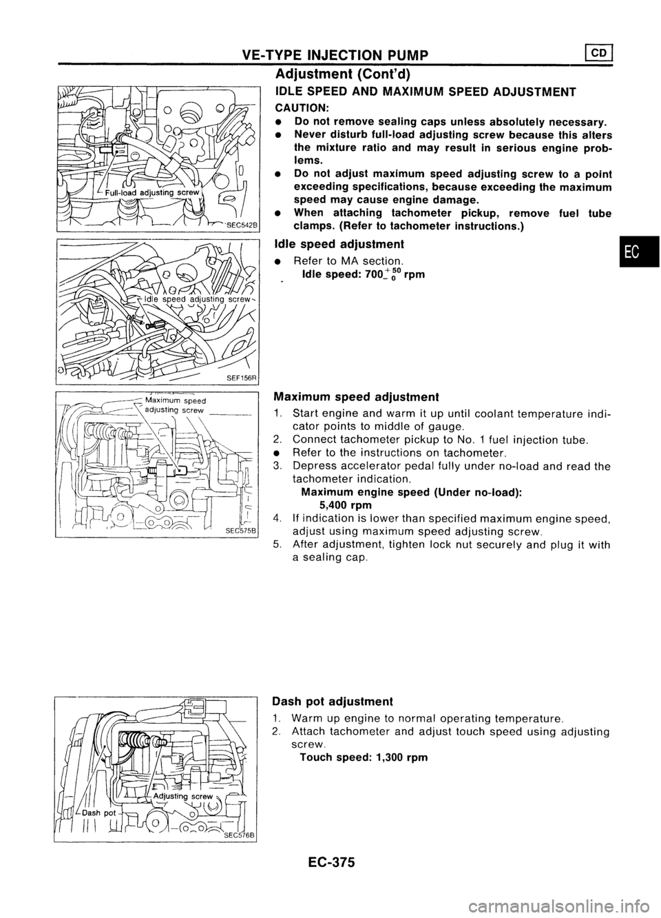
IDLE SPEED ANDMAXIMUM SPEEDADJUSTMENT
CAUTION:
• Donot remove sealingcapsunless absolutely necessary.
• Never disturb full-load adjusting screwbecause thisalters
the mixture ratioandmay result inserious engineprob-
lems.
• Donot adjust maximum speedadjusting screwtoapoint
exceeding specifications, becauseexceeding themaximum
speed maycause engine damage.
• When attaching tachometer pickup,remove fueltUbe
clamps. (Refertotachometer instructions.)
Idle speed adjustment •
• Refer toMA section.
Idle speed:
700~
~o
rpm
SEF156R Maximum speedadjustment
1. Start engine andwarm itup until coolant temperature indi-
cator points tomiddle ofgauge.
2. Connect tachometer pickuptoNO.1 fuelinjection tube.
• Refer tothe instructions ontachometer.
3. Depress accelerator pedalfullyunder no-load andread the
tachometer indication.
Maximum enginespeed(Under no-load):
5,400 rpm
4.
If
indication islower thanspecified maximum enginespeed,
adjust usingmaximum speedadjusting screw.
5. After adjustment, tightenlocknutsecurely andplug itwith
a sealing cap.
Dash potadjustment
1. Warm upengine tonormal operating temperature.
2. Attach tachometer andadjust touchspeed usingadjusting
screw.
Touch speed: 1,300rpm
EC-375
Page 1102 of 1701
relay-2ENGINE
ANDEMISSION CONTROLOVERALLSYSTEM
Component PartsLocation
Engine coolant
temperature sensor
Glowplugs
•
EC-383 SEF159R