Page 1117 of 1701
SEC5658Enginecoolant temperature sensor
Check engine coolant temperature sensorresistance.
Key-in switch
Check continuity betweenterminals ofkey-in switch connector.
11.5
5.6
3.7
1.2
Resistance
kfl
Continuity
No continuity
Continuity shouldexist.
Ignition
key
Not inserted
Inserted
Coolant
temp.°C('F)
-15 (5)
0(32)
10 (50)
40 (104)
TROUBLE
DIAGNOSES
Quick-glow System(Cont'd)
3. Install glowplugconnecting platesecurely.
Connecting
plate
Spring washer
~GIOwnut
Glow harness
Alternator
Refer to"CHARGING SYSTEM"inEL section.
EC-398
Page 1118 of 1701

SYSTEMDESCRIPTION TROUBLE
DIAGNOSES
Partial LoadAdvance (PLA)Control
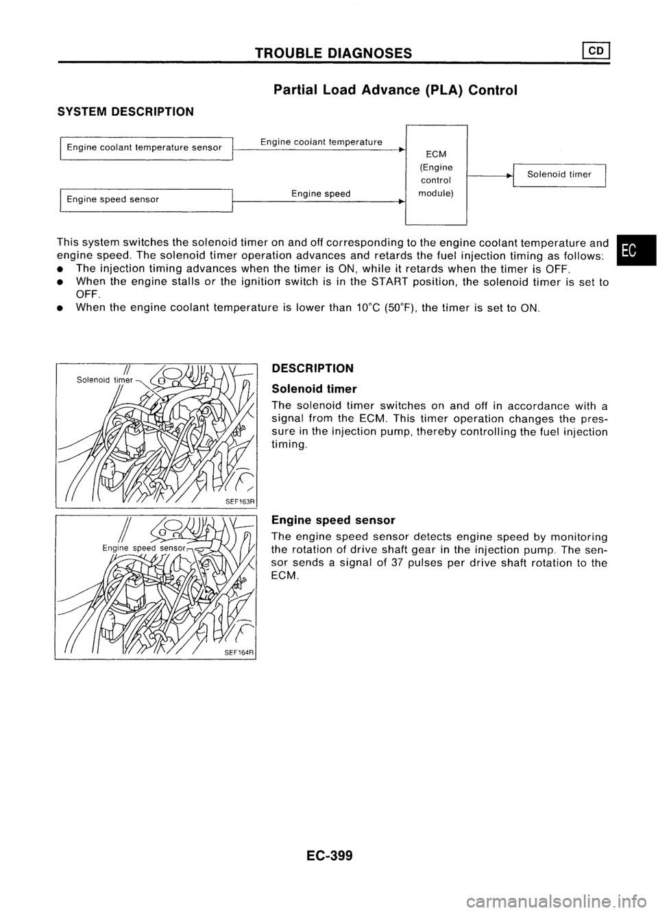
This system switches thesolenoid timeronand offcorresponding tothe engine coolant temperature and
engine speed.Thesolenoid timeroperation advancesandretards thefuel injection timingasfollows:
• The injection timingadvances whenthetimer isON, while itretards whenthetimer isOFF.
• When theengine stallsorthe ignition switchisin the START position, thesolenoid timerisset to
OFF.
• When theengine coolant temperature islower than10°C(50°F), thetimer isset toON.
Engine
coolant temperature sensor
Engine speedsensor Engine
coolant temperature
Engine speed
ECM
(Engine control
module) Solenoid
timer
•
DESCRIPTION
Solenoid timer
The solenoid timerswitches onand offinaccordance witha
signal fromtheECM. Thistimer operation changesthepres-
sure inthe injection pump,thereby controlling thefuel injection
timing.
Engine speedsensor
The engine speedsensor detects enginespeedbymonitoring
the rotation ofdrive shaftgearinthe injection pump.Thesen-
sor sends asignal of37 pulses perdrive shaftrotation tothe
ECM.
EC-399
Page 1119 of 1701
TROUBLEDIAGNOSES ~
Partial LoadAdvance (PLA)Control (Cont'd)
LHD models
EC-PLA-01
~~~~K RefertoEL-POWER.
(JIB)
PLR REVGND-S GND-S
11~81 ~
/12.3
11
13.61
Y L!Y B/W B/W
I
I
f-
t
_I
t
Y ~ L!Y B!W
IrlsJ~ -
M.-B -
~I&~ ---
~r;]ID1
'T'
(E101)
L:jf'
"T'
Y L!Y B!W
1c!J~ ~
~cL~ ---
~c!J1
<=j=
(E231)
=r' =r'
Y L!Y B!W
!
L~Y B~Wt
rrh
m m
ECM
(ENGINECONTROL
MODULE)
@
TW
~
G!B
1
Toengine coolant
._--~. temperature sensor
(Refer toEC-COOL!F.)
II
N•4
1
B/Y
I
B/Y
Iffsn
START
IN;91
BR
I
BR
~
IGN
SOLENOID
TIMER ENGINE
SPEED
SENSOR INJECTION
PUMP
(E214)
~~
~ GY
~
(E214)
\ill)
GY
Refer
tolast page
(Foldout page).
HEC090
EC-400
Page 1120 of 1701
TROUBLEDIAGNOSES ~
Partial LoadAdvance (PLA)Control (Cont'd)
RHO models
EC-PLA-02
FUSE RefertoEL-POWER.
BLOCK
(JIB)
~
PLR REVGND-S GND-S
11~BI ~
11
2•3113.,61
Y L/Y B/wB/W
I
I
f-
t-,t
Y ~ L/Y B/W
I$t _M~-
~t~ -- -
~$I
~
Y L/Y B/W
4r=~~t---~
Y L/Y B/W
!
L~Y B~Wt
m mrn
ECM
(ENGINE
CONTROL
MODULE)
~
•
TW
~
G/B
I
Toengine coolant
.......... ~.temperature sensor
(Refer toEC-COOL/F.)
IN.41
B/Y
I
B/Y
Wail
START
IN;91
BR
I
BR
~
IGN
SOLENOID
TIMER ENGINE
SPEED
SENSOR INJECTION
PUMP
(E214)
Refertolast page
(Foldout page).
~(E203)
rn:rn:tIlID
GY
M\
(~!4)
t:]lV
GY
HECC91
EC-401
Page 1121 of 1701

TROUBLEDIAGNOSES ~
Partial LoadAdvance (PLA)Control (Cont'd)
II
~i5
D~CONNECTORII
lOB
~i5
ECM
M
CONNECTOR
II
10B
SEF040Q
SEF949P
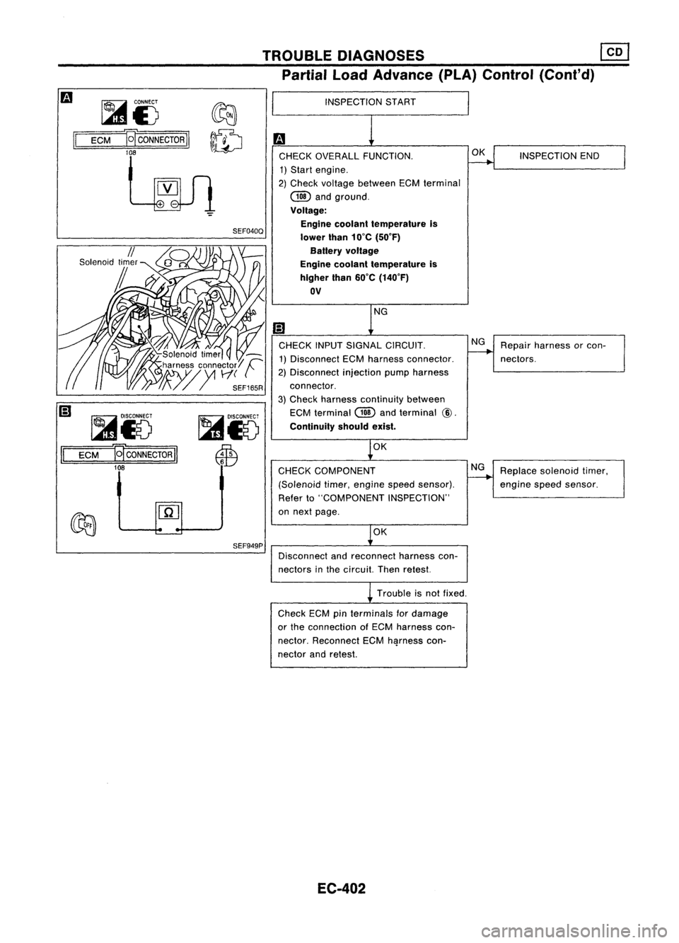
INSPECTION
START
CHECK OVERALL FUNCTION.
1) Start engine.
2) Check voltage between ECMterminal
COO
andground.
Voltage: Engine coolant temperature is
lower than10'C (50'F)
Battery voltage
Engine coolant temperature is
higher than60'C (140'F)
OV
CHECK INPUTSIGNAL CIRCUIT.
1) Disconnect ECMharness connector.
2) Disconnect injectionpumpharness
connector.
3) Check harness continuity between
ECM terminal
COO
andterminal
@.
Continuity shouldexist.
OK
CHECK COMPONENT
(Solenoid timer,engine speedsensor).
Refer to"COMPONENT INSPECTION"
on next page.
OK
Disconnect andreconnect harnesscon-
nectors inthe circuit. Thenretest.
Trouble isnot fixed.
Check ECMpin
terminals
fordamage
or the connection ofECM harness con-
nector. Reconnect ECMh~rness con-
nector andretest.
EC-402 OK
NG
NG
INSPECTION
END
Repair harness orcon-
nectors.
Replace solenoid timer,
engine
speedsensor.
Page 1123 of 1701
TROUBLEDIAGNOSES
Cooling FanControl
SYSTEM DESCRIPTION
Vehicle speedsensor Vehicle
speed
Engine coolant temperature sensorEngine
coolant temperature
ECM
(Engine
control module) Cooling
fan
relay(s)
Air conditioner switch Air
conditioner "ON"signal
The ECM controls thecooling fancorresponding tothe vehicle speed,engine coolant temperature, air
conditioner systempressure andairconditioner ONsignal. Thecontrol system has3-step control
[HIGH/LOW/OFF].
Operation
SEF953P
20
80
(12) (50)
Vehicle speedkmfh(MPH)
~ :Cooling fansoperate at"High" speed.
Air
conditioner switchIs"ON".
100 (212)
95 (203)
90 (194)
~LL
:J
0
eZ;
~o
E
2
C
'"
'0
o
U
Q>
c
'5>
c
w
Air
conditioner switchIs"OFF".
100 (212)
95 (203)
90 (194)
Q>
-
... LL
:J
0
~~
~o
E
2
c
'"
'0
o
U
Q>
c
'5>
c:
w 20
80
(12) (50)
Vehicle speedkmfh(MPH)
o :
Cooling fansdonot operate.
1222l:
Cooling fansoperate at"Low" speed.
EC-404
Page 1125 of 1701
TROUBLEDIAGNOSES
Cooling FanControl (Cont'd)
EC-COOL/F-02
LHDmodels
RHO models
(6):
(B):
I
EeM
(ENGINE
CONTROLMODULE)
@
S/W ~
IciJl
S/W
I
S/W
I~I@QD
;,:@
o
I
iTlJ
S/W S/W
1l@1
100'
GND-S GND-S
L
iJ
ENGINE COOLANT
_ TEMPERATURE
SENSOR
~
lLj:U
S/W
I
~ L
:>
GIS ~
S/W
d!b:. ~ d!b:.
Icpt
(ES-)-
-1~1
GIS
S/W
I I
GIS
t'ETr\'i\
S/W
db ~
,.,.b
1~~-M8--~
GIS
@
S/W
t
GIS
I@I
TW
GIS
It
o
(E203) ~
~11lJ1
GIS
I
@QD~
<:BID
I~I
GIS
t
o
~~
@GY
~(E203)
rnmz:mI
GY
~~
~GY
Refer
tolast page
(Foldout page).
HEC093
EC-406
Page 1127 of 1701
TROUBLEDIAGNOSES
Cooling FanControl (Cont'd)
Checkcooling fanlow
speed control circuit.
(Go to
I
PROCEDURE C
P
Check cooling fanhigh
speed control circuit.
(Go to
I
PROCEDURE D
I.)
NG
NG
INSPECTION
START
OK
CHECK COOLING FANHIGH SPEED
OPERATION. 1) Turn ignition switch"OFF".
2) Reconnect coolingfanrelay-2 and
cooling fanrelay-3.
3) Turn ignition switch"ON".
4) Make surethatcooling fanoperates
at high speed.
CHECK
COOLING FANLOW SPEED
OPERATION. 1) Turn ignition switch"OFF".
2) Disconnect enginecoolant tempera-
ture sensor connector.
SEF168R
3)Disconnect coolingfanrelays 1,2
and 3.
4) Turn ignition switch"ON".
5) Reconnect coolingfanrelay 1.
6) Make surethatcooling fanoperates
at low speed.
SEC163BA OK
INSPECTION END
EC-408