Page 1227 of 1701
CYLINDERBLOCK
CAUTION:
• When installing slidingparts(bearings, pistons,etc.),lubri-
cate contacting surfaceswithnewengine oil.
• Place removed partssuchasbearings andbearing capsin
their proper orderanddirection.
• When installing connecting rodnuts, andmain bearing cap
bolts, apply newengine oiltothreads andseating surfaces.
Disassembly
PISTON ANDCRANKSHAFT
1. Place engine onawork stand.
2. Drain coolant andoil.
3. Remove timingchain.
Refer to"Removal" in"TIMING CHAIN"(EM-20).
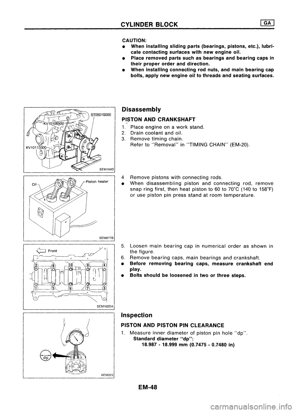
4 Remove pistonswithconnecting rods.
• When disassembling pistonandconnecting rod,remove
snap ringfirst, thenheat piston to60 to70°C (140to158°F)
or use piston pinpress stand atroom temperature.
5. Loosen mainbearing capinnumerical orderasshown in
the figure.
6. Remove bearingcaps,mainbearings andcrankshaft.
• Before removing bearingcaps,measure crankshaft end
play.
• Bolts should beloosened intwo orthree steps.
AEM023 Inspection
PISTON ANDPISTON PINCLEARANCE
1. Measure innerdiameter ofpiston pinhole "dp".
Standard diameter
"dp":
18.987 -18.999
mm
(0.7475 -0.7480
in)
EM-48
Page 1238 of 1701
OUTERCOMPONENT PARTS
•
SEM231F
SEC.
130-140-150-210-211-221
~ __to:J
13•16 (1.3 -1.6, 9.12)
to:J
16•21 (1.6. 2.1,12. 15)
to:J
20•29
(2.0 •3.0,
14 .22)
to:J
41-52 (4.2 -5.3, 30-38)
~---- D_?
. 'J ~
~~~ 0
-t::;-.....~ /,
0
to:J
21-26 ./"
(2.1. 2.7, ,./"~/'
12 -1~)
fs\
19-~~7
~ to:J
16•21
Q
to:J
18. 21 ,
to:J
45_60 (1.6-2.1, 0
Ii]
6.3 _8.3
(1.8 •2.1, (4.6•6.1, 12•15)
1
(0.64•0.85,
to:J
16•19 13-15)
to:J
16•21 33•44)
(1.6 -1.9, (1.6-2.1,
to:J
16•21
12 -14)
12•15)
t"J
16•,.
f"-~
t"J
15•21
r::!
*
H
...----4lJ
~~'. '1~
J
r \~ ~~'..,:;
1,
~Q.
/¥i-;:
--'Il
1il3.7 -5.0
J~
--A)
to:J
16-21
~11V>/
(0.38 _0.51, A~ - (1.6.2.1,12•15)\...,//
~to:J
20.29(2.0-3.0, 14-22)
33.0 •44.3)
Y
&'/-
:f~l
to:J
20•26 (2.0 •2.7, 14-20)
to:J :
N'm (kg-m, fl-Ib)
to:J
16-21 (1.6 -2.1, 12-15)~/
Ii] :
N'm (kg-m, in-Ib) •
~ :Apply
liquidgasket.
*:
Refer toLC section
("Thermostat", "ENGINECOOLING SYSTEM").
G)
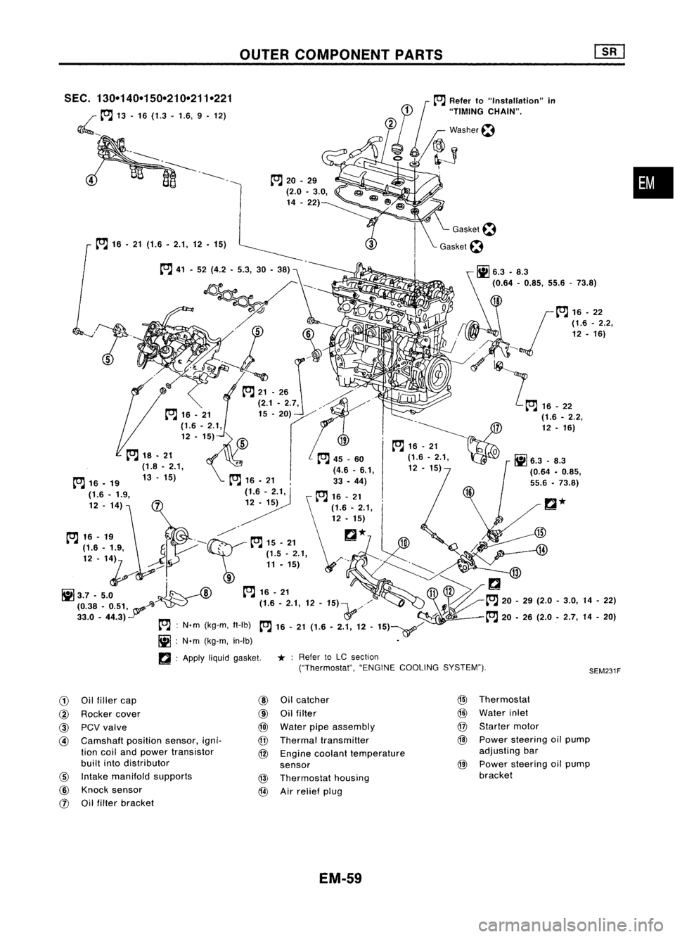
Oilfiller cap
@
Oilcatcher
@
Thermostat
@
Rocker cover
@
Oilfilter
@
Water inlet
@
PCVvalve
@
Water pipeassembly
@
Starter motor
@
Camshaft
positionsensor,igni-
@
Thermal transmitter
@
Power steering oilpump
tion coiland power transistor
@
Engine coolant temperature adjusting
bar
built intodistributor
sensor
@
Power
steering oilpump
@
Intake manifold supports
@
Thermostat housing bracket
@
Knock sensor
@
Airrelief plug
rJ)
Oilfilter bracket
EM-59
Page 1248 of 1701
TIMINGCHAIN
CAUTION:
• After removing timingchain,donot turn crankshaft and
camshaft separately, orvalves willstrike piston heads.
• When installing rockerarms,camshafts, chaintensioner, oil
seals, orother sliding parts,lubricate contacting surfaces
with newengine oil.
• Apply newengine oiltobolt threads andseat surfaces when•
installing cylinderhead,camshaft sprockets, crankshaft
pulley, andcamshaft brackets.
Removal
1. Release fuelpressure.
Refer to"Releasing FuelPressure" inEC section.
2. Remove engineundercovers.
3. Remove frontRHwheel andengine sidecover.
4. Drain coolant byremoving cylinderblockdrainplugand
radiator draincock.
5. Remove radiator.
6. Remove airduct tointake manifold.
7. Remove drivebeltsandwater pumppulley.
8. Remove alternator andpower steering oilpump.
9. Remove vacuumhoses,fuelhoses, wires,harness, connec-
tors andsoon.
10. Remove allspark plugs.
11. Remove rockercoverandoilseparator.
12. Remove intakemanifold supports.
EM-69
Page 1260 of 1701
Unit:mm(in)
10
(0.39)
n'
Engine front
1+ .,..I
3 (0.12) ~LiqUid
gasket
SEM366D TIMING
CHAIN
Installation (Cont'd)
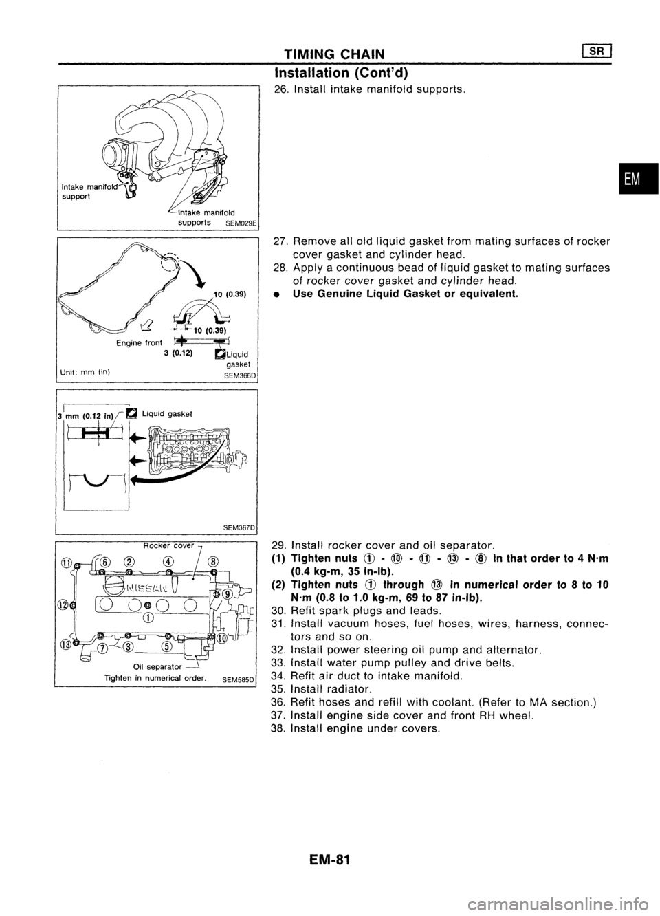
26. Install intakemanifold supports.
27. Remove allold liquid gasket frommating surfaces ofrocker
cover gasket andcylinder head.
28. Apply acontinuous beadofliquid gasket tomating surfaces
of rocker covergasket andcylinder head.
• Use Genuine LiquidGasket orequivalent.
•
3
1
mm (0.12
In)r~
liquidgasket
tJ$j
SEM367D
@
8l"-L~~[c,.l~
Q
[0 O@O 0
CD
Oil separator
Tighten innumerical order.
SEM585D
29.
Install rocker coverandoilseparator.
(1) Tighten nuts
C!J-
@l -
@ -@ -
cID
inthat order to4N'm
(0.4 kg-m, 35in-Ib).
(2) Tighten nuts
d)
through @innumerical orderto8to 10
N'm (0.8to1.0 kg-m, 69to87 in-Ib).
30. Refit spark plugsandleads.
31. Install vacuum hoses,fuelhoses, wires,harness, connec-
tors andsoon.
32. Install power steering oilpump andalternator.
33. Install waterpumppulley anddrive belts.
34. Refit airduct tointake manifold.
35. Install radiator.
36. Refit hoses andrefill withcoolant. (RefertoMA section.)
37. Install engine sidecover andfront RHwheel.
38. Install engine undercovers.
EM-81
Page 1278 of 1701
SEM092DENGINE
REMOVAL
WARNING:
• Situate vehicle onaflat and solid surface.
• Place chocks atfront andback ofrear wheels.
• Donot remove engineuntilexhaust systemhascompletely
cooled off.
Otherwise, youmay burn yourself and/orfiremay break out
in fuel line.
• For safety during subsequent steps,thetension ofwires
should beslackened againsttheengine.
• Before disconnecting fuelhose, release fuelpressure from
fuel line.
Refer to"Releasing FuelPressure" inEC section.
• Besure tohoist engine andtransaxle inasafe manner.
• For engines notequipped withengine slingers, attach
proper slingers andbolts described inPARTS CATALOG.
CAUTION:
• When liftingengine, becareful nottostrike adjacent parts,
especially thefollowing: Accelerator wirecasing, brake
lines, andbrake master cylinder.
• Inhoisting theengine, alwaysuseengine slingers inasafe
manner.
Removal
1. Remove engineundercoverandhood.
2. Drain coolant frombothcylinder block,andradiator.
3. Drain engine oilfrom drain plugofoil pan.
4. Remove vacuumhoses,fuelhoses, wires,harness andcon-
nectors andsoon.
5. Remove exhausttubes,balljoints anddrive shafts.
6. Remove radiatorandfans.
7. Remove drivebelts.
8. Remove alternator, compressor andpower steering oil
pump fromengine.
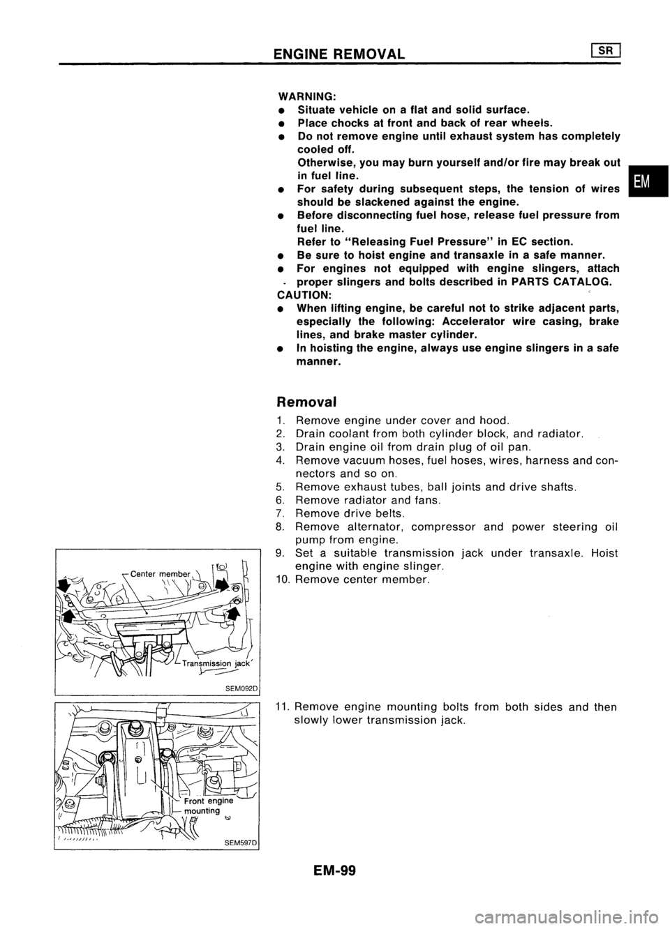
9. Set asuitable transmission jackunder transaxle. Hoist
engine withengine slinger.
10. Remove centermember.
11. Remove enginemounting boltsfrombothsides andthen
slowly lowertransmission jack.
EM-99
•
Page 1299 of 1701
TIMINGBELT
Camshaft TimingBelt
CAUTION:
a. Donot bend ortwist timing belt.
b. After removing timingbelt,donot turn crankshaft andcamshaft separately becausevalveswillstrike
piston heads.
c. Ensure thattiming belt,camshaft sprocket,crankshaft sprocketandbelttensioner areclean andfree
from oiland water.
~: N.m(kg-m, in-Ib)
A:
N.m(kg-m, ft-Ib)
L :Locking sealant
C"O
Front camshaft sprocket
@
Idler
@
Belttensioner
@
Crankshaft sprocket
@
Beltcover lower
@
Beltcover center (Engine
mounting bracket)
(1)
Timing belt
@)
~5 {O.'-0.5, "-
43'
SEM046FA
@
Beltcover upper
@
Gasket
@)
Front camshaft sprocketplate
REMOVAL
1. Drain engine coolant fromradiator.
2. Remove upperradiator hoseandupper beltcover.
3. Remove waterpumppulley.
EM-120
Page 1301 of 1701
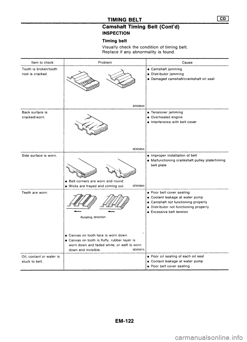
TIMINGBELT
Camshaft TimingBelt(Cont'd)
INSPECTION
Timing belt
Visually checkthecondition oftiming belt.
Replace ifany abnormality isfound.
Item tocheck
Tooth isbroken/tooth
root iscracked.
Back surface is
cracked/worn. Problem
SEM394A
SEM395A
Cause
• Camshaft jamming
• Distributor jamming
• Damaged camshaft/crankshaft oilseal
• Tensioner jamming
• Overhe
ed
engine
• Interference withbeltcover
Side surface isworn. •
Improper installation ofbelt
• Malfunctioning crankshaftpulleyplate/timing
belt plate
• Belt corners areworn andround.
• Wicks arefrayed andcoming out.
SEM396A
Teeth areworn.
-
Rotating direction
-
•
Poor belt
cover
sealing
• Coolant leakageatwater pump
• Camshaft notfunctioning properly
• Distributor notfunctioning properly
• Excessive belttension
Oil, coolant orwater is
stuck tobelt.
•
Canvas
ontooth faceisworn down.
• Canvas
ontooth isfluffy, rubber layeris
worn down andfaded white, orweft isworn
down andinvisible.
SEM397A
EM-122
•
Poor oilsealing ofeach oilseal
• Coolant leakageatwater pump
• Poor belt
cover
sealing
Page 1308 of 1701
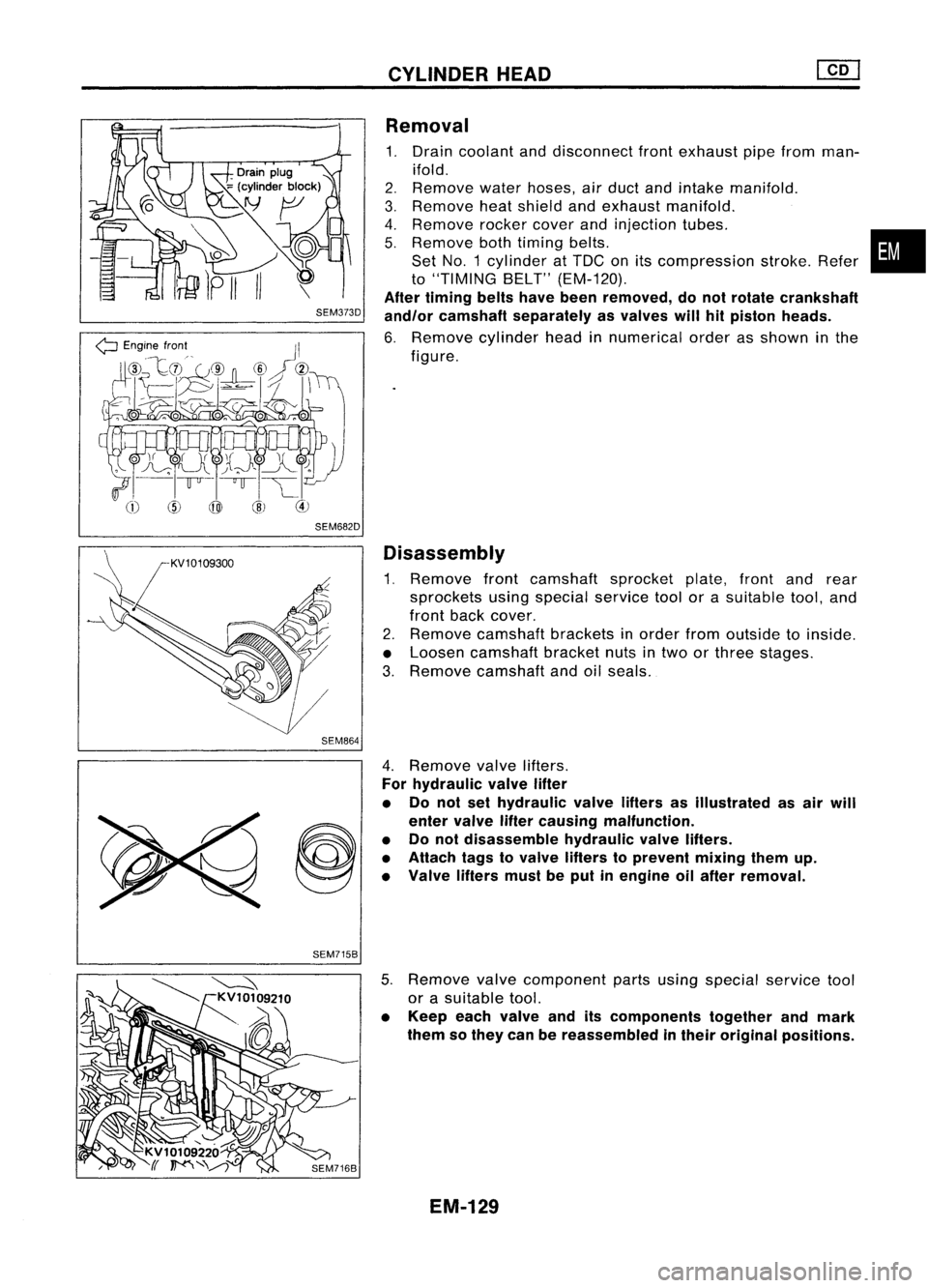
SEM373D
SEM682D SEM864
CYLINDER
HEAD
Removal
1. Drain coolant anddisconnect frontexhaust pipefrom man-
ifold.
2. Remove
waterhoses, airduct andintake manifold.
3. Remove
heatshield andexhaust manifold.
4. Remove
rocker
cover
andinjection tubes.
5. Remove
bothtiming belts.
Set NO.1 cylinder atTDC onitscompression stroke.Refer
to
"TIMING BELT"(EM-120).
After timing beltshavebeen removed, donot rotate crankshaft
and/or camshaft separately asvalves willhitpiston heads.
6. Remove
cylinderheadinnumerical orderasshown inthe
figure.
Disassembly
1. Remove frontcamshaft sprocketplate,frontandrear
sprockets usingspecial
service
toolorasuitable tool,and
front back
cover.
2. Remove
camshaft bracketsinorder fromoutside toinside.
• Loosen camshaft bracketnutsintwo orthree stages.
3. Remove
camshaft andoilseals.
•
SEM715B 4.
Remove valve
lifters.
For hydraulic valvelifter
• Do not sethydraulic valvelifters asillustrated asair will
enter valve liftercausing malfunction.
• Donot disassemble hydraulicvalvelifters.
• Attach tagstovalve lifters toprevent mixingthemup.
• Valve liftersmustbeput inengine oilafter removal.
5. Remove
valve
component partsusing special
service
tool
or asuitable tool.
• Keep eachvalve anditscomponents togetherandmark
them sothey canbereassembled intheir original positions.
EM-129