Page 1132 of 1701
TROUBLEDIAGNOSES
Air Conditioner CutControl
SYSTEM DESCRIPTION
The airconditioner isturned offunder thefollowing conditions:
RHO models .
• Engine coolant temperature ishigher than
grC
(20rF)
LHD models
• Engine coolant temperature ishigher than105°C (221°F)
For trouble diagnoses, referto"TROUBLE DIAGNOSES" inHA section.
Air
conditioner switch
Engine coolant temperature sensor
A/C
ONsignal
Engine coolant temperature
ECM
(Engine
control module) Air
condi-
tioner relay
•
EC-413
Page 1136 of 1701

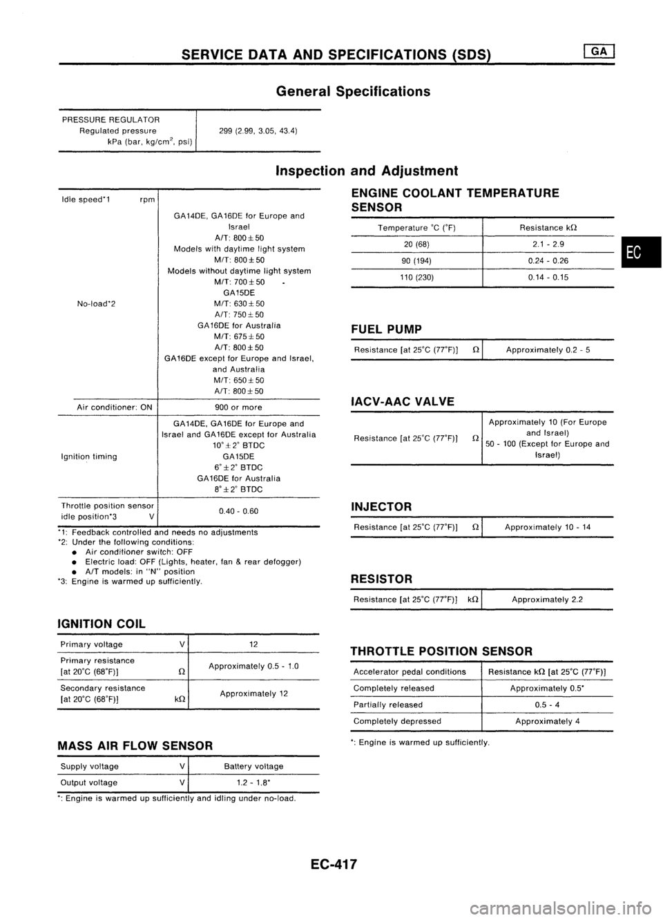
SERVICEDATAANDSPECIFICATIONS (SOS)
General Specifications
PRESSURE REGULATOR
Regulated pressure
kPa (bar, kg/cm
2,
psi) 299
(2.99, 3.05,43.4)
Idle speed'1
rpm
Inspection
andAdjustment
ENGINE COOLANT TEMPERATURE
SENSOR
Temperature
'c
('F) Resistancekn
20 (68) 2.1
-2.9
•
90
(194) 0.24-0.26
110 (230) 0.14-0.15
No-load'2
Air conditioner: ONGA
14DE, GA16DE forEurope and
Israel
AIT: 800:1:50
Models withdaytime lightsystem
MIT: 800:1:50
Models withoutdaytime lightsystem
M/T: 700:1:50
GA15DE
M/T: 630:1: 50
A/T: 750:1: 50
GA 16DE forAustralia
M/T: 675:1: 50
A/T: 800:1:50
GA16DE exceptforEurope andIsrael,
and Australia
M/T: 650:1:50
A/T: 800:1: 50
900 ormore
FUEL
PUMP
Resistance [at25'C (77'F)] n
IACV-AAC VALVE
Approximately
0.2-5
Ignition timing GA
14DE, GA16DE forEurope and
Israel andGA16DE except forAustralia
10':1:2' BTDC
GA15DE
6':1:2' BTDC
GA16DE forAustralia
8':1:2' BTDC Resistance
[at25'C (77'F)) Approximately
10(For Europe
n andIsrael)
50 -100 (Except forEurope and
Israel)
0.40. 0.60
Throttle
position sensor
idle position'3 V
'1: Feedback controlled andneeds noadjustments
'2: Under thefollowing conditions:
• Air conditioner switch:OFF
• Electric load:OFF(Lights, heater,fan
&
rear defogger)
• A/T models: in"N" position
'3: Engine iswarmed upSUfficiently.
IGNITION COIL INJECTOR
Resistance [at25'C (77'F)) n
RESISTOR
Resistance [at25'C (77'F)] kn Approximately
10.14
Approximately 2.2
THROTTLE POSITIONSENSOR
Primary
voltage
Primary resistance
[at 20'C (68'F)]
Secondary resistance
[at 20'C (68'F)]
V
n
kn
12
Approximately 0.5-1.0
Approximately 12 Accelerator
pedalconditions
Completely released
Partially released
Completely depressed Resistance
kn[at25'C (77'F))
Approximately 0.5'
0.5 -4
Approximately 4
MASS AIRFLOW SENSOR
':
Engine iswarmed upsufficiently.
Supply voltage
Output voltage
V
V
Battery
voltage
1.2 -1.8'
': Engine iswarmed upSUfficiently andidling under no-load.
EC-417
Page 1137 of 1701

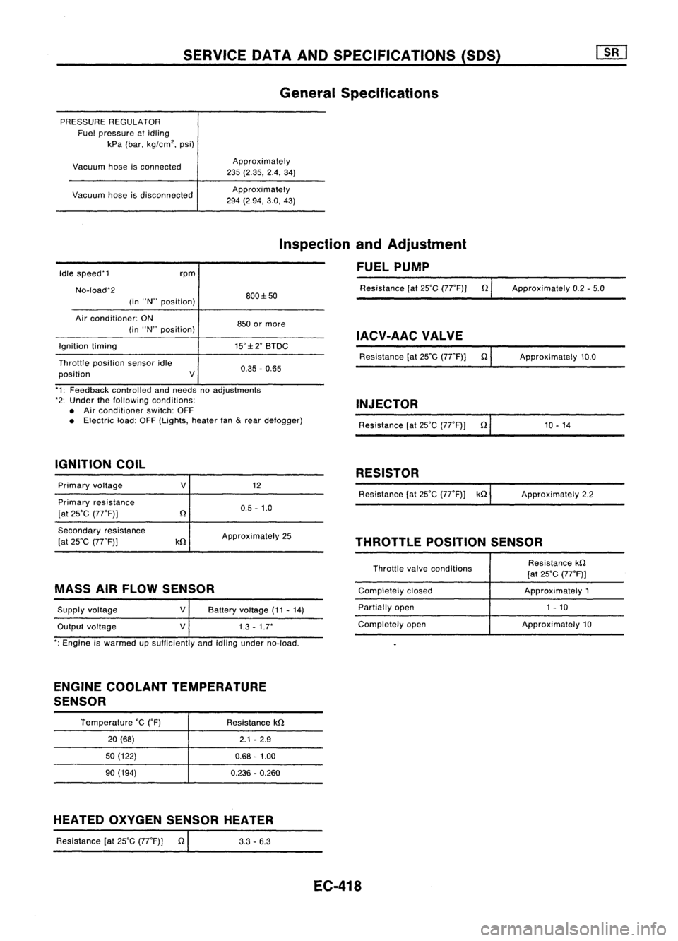
SERVICEDATAANDSPECIFICATIONS (SOS)
General Specifications
PRESSURE REGULATOR
Fuel pressure atidling
kPa (bar, kg/cm
2,
psi)
Vacuum hoseisconnected
Vacuum hoseisdisconnected Approximately
235 (2.35. 2.4.34)
Approxi mately
294 (2.94, 3.0,43)
Idle speed'1
No-load'2 rpm
(in "N" position) 800:1:50
Inspection
andAdjustment
FUEL PUMP
Resistance [at25'C (77'F)] n
Approximately 0.2-5.0
Air conditioner: ON
(in "N" position)
Ignition timing
Throttle position sensoridle
position V850
ormore
IACV-AACVALVE
15':1:2' BTDC
Resistance[at25'C (77'F)] n
0.35 -0.65 Approximately
10.0
'1: Feedback controlled andneeds noadjustments
'2: Under thefollowing conditions:
• Air conditioner switch:OFF
• Electric load:OFF(Lights, heaterfan
&
rear defogger)
IGNITION COIL INJECTOR
Resistance [at25'C (77'F)) n'
1_0_-_1_4 _
RESISTOR
Primary voltage
Primary resistance
[at 25'C (77'F))
V
12
0.5 -1.0 Resistance
[at25'C (77'F)) kn ApproXimately 2.2
Secondary resistance
[at 25'C (77'F))
kn
Approximately
25
THROTTLEPOSITIONSENSOR
MASS AIRFLOW SENSOR
Supply voltage
Output voltage
V
V
Battery
voltage (11-14)
1.3 -1.7'
Throttle
valveconditions
Completely closed
Partially open
Completely open Resistance
kn
[at 25'C (77'F)]
Approximately 1
1 - 10
Approximately 10
': Engine iswarmed upsufficiently andidling under no-load.
ENGINE COOLANT TEMPERATURE
SENSOR
Temperature
'c
('F)
20 (68)
50 (122)
90 (194) Resistance
kn
2.1-2.9
0.68 -1.00
0.236 -0.260
HEATED OXYGEN SENSOR HEATER
Resistance [at25'C (77'F)] n
I
3.3-6.3
EC-418
Page 1140 of 1701
Inner
side
SEM164F PRECAUTION
LIQUID GASKET APPLICATION PROCEDURE
a. Use ascraper toremove alltraces ofold liquid gasket from
mating surfaces andgrooves. Also,completely cleananyoil
from these areas.
b. Apply acontinuous beadofliquid gasket tomating surfaces.
(Use Genuine LiquidGasket orequivalent.)
• For oilpan, besure liquid gasket diameter is4.0 to5.0
mm (0.157 to0.197 in)for SRengine and3.5to4.5 mm
(0.138 to0.177 in)except forSRengine.
• For areas except oilpan, besure liquid gasket diameter
is 2.0 to3.0 mm (0.079 to0.118 in).
c. Apply liquidgasket toinner sealing surface aroundhole
perimeter area.
(Assembly shouldbedone within 5minutes aftercoating.)
d. Wait atleast 30minutes beforerefilling engineoiland
engine coolant.
LC-2
Page 1151 of 1701
ENGINECOOLING SYSTEM
IiJ
6.28 -8.34 (0.641 -0.851, 55.6-73.8)
SEC.
210 Water
Pump
~ 6.28 -8.34 (0.641 -0.851, 55.6-73.8)
WaterpumppUlley
l
~Liquid gasket
~ N.m(kg-m, in-Ib)
SLC989AB
•
CAUTION:
• When removing waterpumpassembly, becareful nottoget
coolant ontiming chain.
• Water pumpcannot bedisassembled andshould be
replaced asaunit.
• After installing waterpump, connect hoseandclamp
securely, thencheck forleaks using radiator captester.
REMOVAL
1. Drain coolant fromradiator andcylinder block.
2. Remove drivebeltsforcompressor, powersteering pump
and alternator.
3. Remove waterpumppulley.
4. Remove waterpump.
INSPECTION
1. Check bodyassembly forrust orcorrosion.
2. Check forrough operation duetoexcessive endplay.
SLC162A LC-13
Page 1154 of 1701
SEC.214
10
~ :N.m (kg-m, in-Ib)
ENGINE
COOLING SYSTEM
Radiator
~~ 3.7.5.0(0.38-0.51, 33.0•44.3)
~~ 3.8.4.5 (0.39 •0.46, 33.9.39.9)
. I
L!
\[jj
3.'-4.5 (0.39 -0.45,3>' -39.')
~,,~ 'fl
'~~WI-
1
I
--
5'\
,
),
"~
" It, -~ ~,.../ "---./"-- ~~
n.- /
i ~
r~ ~ ~'".~
i
@
'0)"
I
I
Jl~J)
1~~
6.86 •
~ "" <>!.
0
(0.70,60.7)
",,~~@
SLC991AB
G)
Reservoir tank
@
Reservoir tankbracket
@
Radiator cap
@
Mounting bracket
@
Upper hose
@
Washer
(J)
Drain plug
@
Mounting rubber
@
Oilcooler hose(AfTmodels)
@l
Radiator
@
Lower hose
@
Cooling fan
@
Cooling fanmotor
Cooling fancontrol system
• Cooling fansarecontrolled bythe ECM. Fordetails, referto
EC section ("Cooling FanControl", "TROUBLE DIAG-
NOSES").
Refilling enginecoolant
• For details onrefilling enginecoolant, refertoMA section
("REFILLING ENGINECOOLANT", "ChangingEngine
Coolant").
LC-16
Page 1160 of 1701

A16-21
N.m ~/
(1.6 •2.1 kg-m,
12 -15
ft.lb)
ENGINE
COOLING SYSTEM
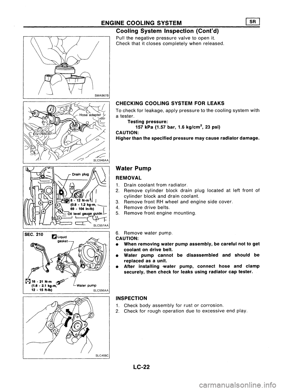
Cooling SystemInspection (Cont'd)
Pull thenegative pressure valvetoopen it.
Check thatitcloses completely whenreleased.
CHECKING COOLINGSYSTEMFORLEAKS
To check forleakage, applypressure tothe cooling systemwith
a tester.
Testing pressure:
157 kPa (1.57 bar,1.6kg/cm
2,
23psi)
CAUTION:
Higher thanthespecified pressuremaycause radiator damage.
Water Pump
REMOVAL
1. Drain coolant fromradiator.
2. Remove cylinderblockdrain pluglocated atleft front of
cylinder blockanddrain coolant.
3. Remove frontRHwheel andengine sidecover.
4. Remove drivebelts.
5. Remove frontengine mounting.
6. Remove waterpump.
CAUTION:
• When removing waterpumpassembly, becareful nottoget
coolant ondrive belt.
• Water pumpcannot bedisassembled andshould be
replaced asaunit.
• After installing -waterpump, connect hoseandclamp
securely, thencheck forleaks using radiator captester.
INSPECTION
1. Check bodyassembly forrust orcorrosion.
2. Check forrough operation duetoexcessive endplay.
SLC408C LC-22
Page 1162 of 1701

ENGINECOOLING SYSTEM ~
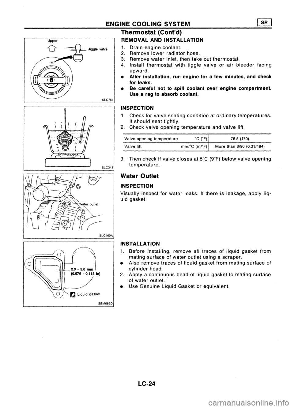
Thermostat
(Cont'd)
Upper REMOVALANDINSTAllATION
;::g=
Jigglevalve
1.Drain engine coolant.
2. Remove lowerradiator hose.
3. Remove waterinlet,thentake outthermostat.
4. Install thermostat withjiggle valveorair bleeder facing
upward.
• After installation, runengine forafew minutes, andcheck
for leaks.
• Becareful nottospill coolant overengine compartment.
Use arag toabsorb coolant.
SLC767
INSPECTION
1. Check forvalve seating condition atordinary temperatures.
It
should seattightly.
2. Check valveopening temperature andvalve lift.
Valve opening temperature
°c
(OF) 76.5(170)
Valve lift mmrC(inrF) Morethan
8/90(0.31/194)
3. Then check ifvalve closes at5°C (9°F) below valveopening
temperature.
Water Outlet
INSPECTION
Visually inspectforwater leaks.
If
there isleakage, applyliq-
uid gasket.
SLC460A INSTAllATION
1. Before installing, removealltraces ofliquid gasket from
mating surface ofwater outlet usingascraper.
• Also remove tracesofliquid gasket frommating surface of
cylinder head.
2. Apply acontinuous beadofliquid gasket tomating surface
of water outlet. .
• Use Genuine LiquidGasket orequivalent.
~ Liquid gasket
SEM086D
LC-24