1995 NISSAN ALMERA N15 engine coolant
[x] Cancel search: engine coolantPage 989 of 1701
TROUBLEDIAGNOSIS -General Description
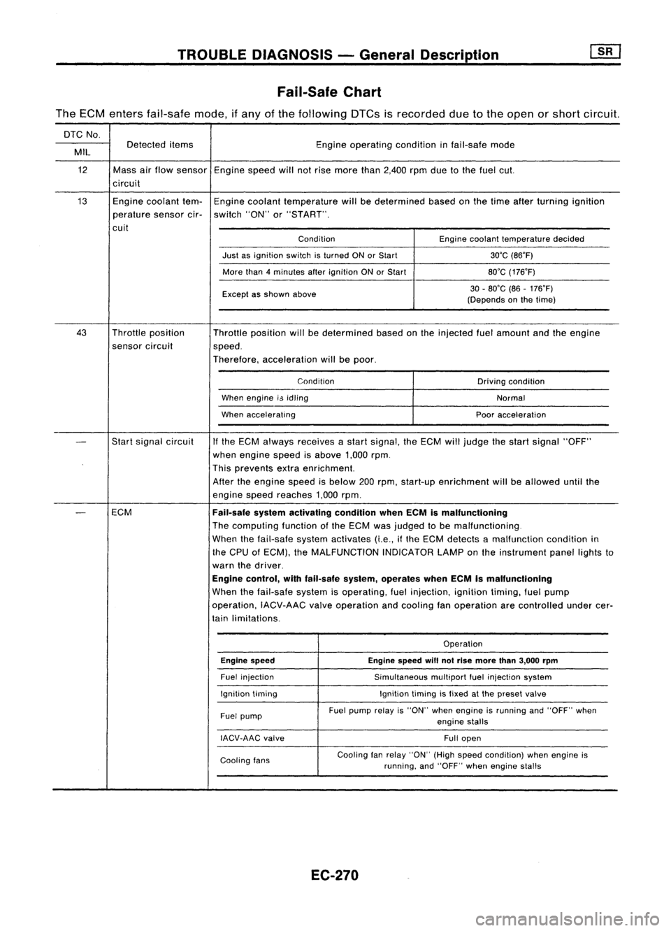
Fail-Safe Chart
The ECM enters fail-safe mode,ifany ofthe following DTCsisrecorded duetothe open orshort circuit.
DTC No.
Detected items Engineoperating conditioninfail-safe mode
MIL
12 Massairflow sensor Enginespeedwillnotrise more than2,400 rpmduetothe fuel cut.
circuit
13 Enginecoolant tem-Engine coolant temperature willbedetermined basedonthe time after turning ignition
perature sensorcir-switch "ON"or"START".
cuit ConditionEnginecoolant temperature decided
Just asignition switchisturned ONorStart 30'C(86'F)
More than4minutes afterignition ONorStart 80'C(176'F)
Except asshown above 30
-80'C (86-176'F)
(Depends onthe time)
43 Throttle position
Throttleposition willbedetermined basedonthe injected fuelamount andtheengine
sensor circuit
speed.
Therefore, acceleration willbepoor.
Condition Drivingcondition
When engine i$idling
Normal
When accelerating Pooracceleration
-
Start
signal circuit
If
the ECM always receives astart signal, theECM willjudge thestart signal "OFF"
when engine speedisabove 1,000rpm.
This prevents extraenrichment.
After theengine speedisbelow 200rpm, start-up enrichment willbeallowed untilthe
engine speedreaches 1,000rpm.
-
ECM
Fail-safesystemactivating conditionwhenECMismalfunctioning
The computing functionofthe ECM wasjudged tobe malfunctioning.
When thefail-safe systemactivates (i.e.,ifthe ECM detects amalfunction conditionin
the CPU ofECM), theMALFUNCTION INDICATORLAMPonthe instrument panellightsto
warn thedriver.
Engine control, withfail-safe system,operates whenECMismalfunctioning
When thefail-safe systemisoperating, fuelinjection, ignitiontiming,fuelpump
operation, IACV-AACvalveoperation andcooling fanoperation arecontrolled undercer-
tain limitations.
Operation
Engine speed Enginespeedwillnotrise more than3,000 rpm
Fuel injection
Simultaneousmultiportfuelinjection system
Ignition timing Ignitiontimingisfixed atthe preset valve
Fuel pump Fuel
pump relayis"ON" whenengine isrunning and"OFF" when
engine stalls
IACV-AAC valve
Fullopen
Cooling fans Cooling
fanrelay "ON" (Highspeed condition) whenengine is
running, and"OFF" whenengine stalls
EC-270
Page 994 of 1701
TROUBLEDIAGNOSIS -General Description
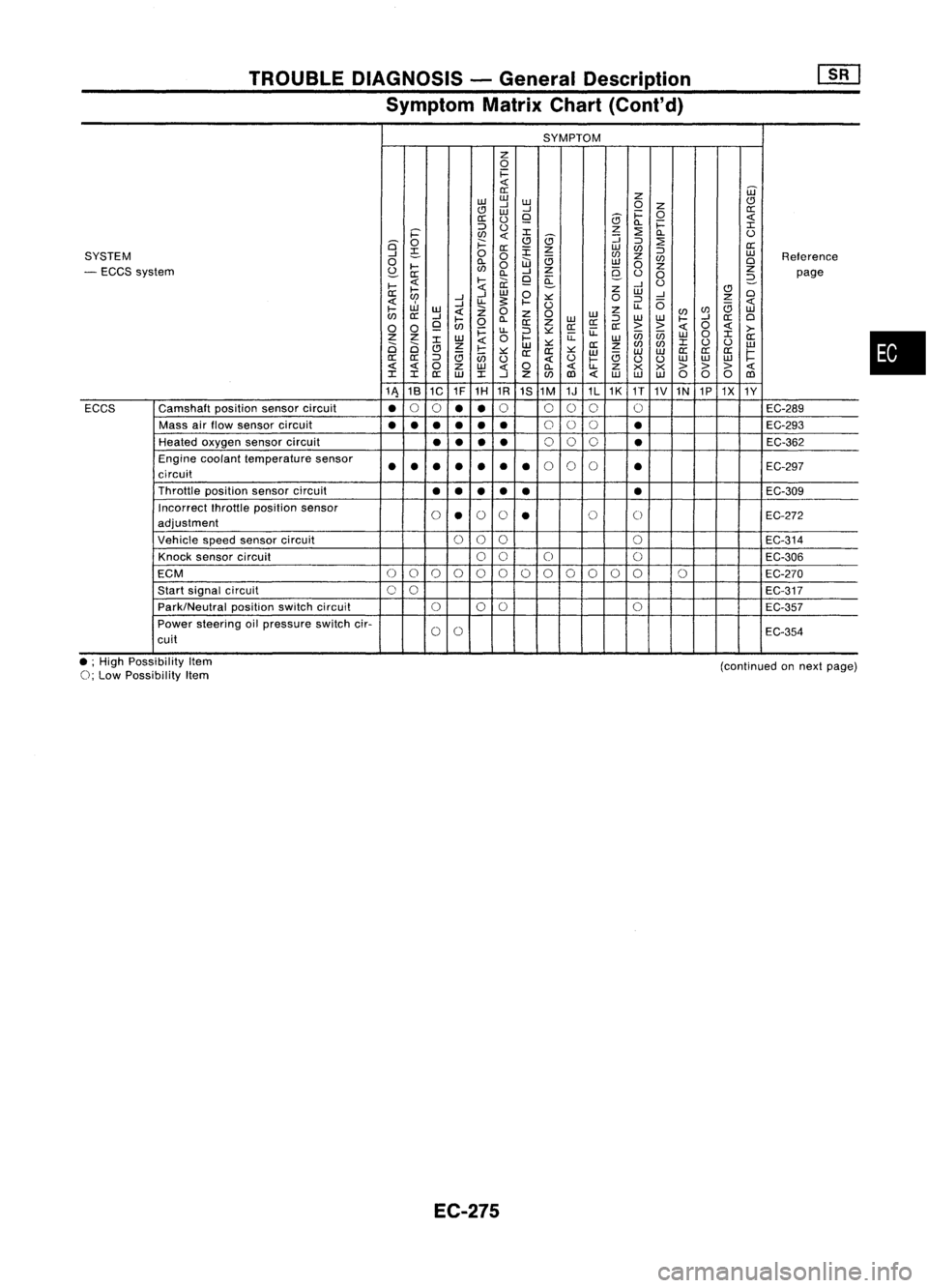
Symptom MatrixChart(Cont'd)
SYMPTOM
z
0
1=
0::
Z
W
w w
CJ
..J
W
0
Z
CJ
W
..J
1=
0
0::
0::
()
9
5
Q.
1=
::::>
()
z
:2
I
i='
en
I
5
::;
Q.
()
is'
0
;:::
CJ
::::>
:2
0::
~
0::
:r:
z
w
en
::::>
SYSTEM
..J
0
0
en
z
w
Reference
0
Q.
W
e;
w
en
0
- ECCS system
~
....
en
0
..J
Z
9-
0
z
Z
0::
Q.
9
a:
()
0
2-
page
....
....
ii:
..J
U
....
Z
CJ
0::
..J
W
0
W
..J
0
en
..J
u-
s:
.... ::.:::
0
::::>
0
z
W
..J
U
u-
e;
....
w
Z
0
z
0
w
z
(/)
en
w
en
0::
..J
....
Q.
W
::::>
w
w
....
..J
0::
0
0 0
9
en
0
0::
Z
0::0::
0::
>>
0
>-
~
u-
::::>::.:::
u:
enen
0
I
Z Z
W
0
....
u:
w
W
0::
2i 2i
I
Z
W
::.:::
0::
z
en
(/)
I
()
()
w
CJ
e;
....
::.:::
0:: 0::
::.:::
w w
W
0::
0::
0::
1=
0::
0::
::::>
en
()
()
....
e;
uu
w
w
w
0
Z
w
0
Q.
u-
Z
x x
> >>
I I
0::
W
I
..J
Z
(/)
1Il
w
w w
000
1Il
11\ 18
1C 1F
1H 1R
1S1M 1J1L1K
1T
1V1N 1P1X
1Y
ECCS Camshaft
positionsensorcircuit
•
0
0
••
0
000 0
EC-289
Mass airflow sensor circuit
•••
•••
0
00
•
EC-293
Heated oxygen sensorcircuit
••
••
0
00
•
EC-362
Engine coolant temperature sensor
••• ••
•
•
0
0
0
•
EC-297
circuit
Throttle positionsensorcircuit
••
••
• •
EC-309
Incorrect fhrottleposition sensor
0
•
0
0
•
0
0
EC-272
adjustment
Vehicle speedsensor circuit
000
0
EC-314
Knock sensor circuit
00
0 0
EC-306
ECM
0
0
0
0
00000
0
00 0
EC-270
Start signal circuit
00
EC-317
Park/Neutral positionswitchcircuit
000
0
EC-357
Power steering oilpressure switchcir-
0
0
EC-354
cuit
•
• ;High Possibility Item
0;
Low Possibility Item
EC-275
(continued
onnext page)
Page 995 of 1701
TROUBLEDIAGNOSIS -General Descrip_tio_n
1s_R_1
Symptom MatrixChart(Cont'd)
SYMPTOM
z
0
i=
«
W
a:
z
w
w
w
CJ
CJ
....J
....J
0
Z
a:
w
i=
0
a:
(.)
9
8
«
0.. i=
:I:
::J
(.)
z
:2
i='
en
«
:I:
8
:J
0..
(.)
Q
0
f:::.
CJ
:J
:2
a:
a:
:E
z
w
en
SYSTEM
....J
~
0
0
en
z
:J
w
Reference
0
0..
W
a
w
en
Cl
- Engine mechanical
&
other
I-
en
0
z
0
z
z
S:?-
a: 0..
....J
e-
(.)
0
page
I-
«
l-
ii.
9
~
....J
(.)
2-
a:
~
«
w
0
z
w
CJ
Cl
....J ....J
:.:::
0
:J
....J
Z
«
....J
u.
~
I-
(.)
u..
0
a
«
I-
w
«
Z
0
z
enen
w
en
a:
....J
I-
0..
Z
0
WW
:J
W
W
I-
....J
a:
Cl
0 0
9
en
0
a:
z
a:a:
a:
> >
«
0
«
>-
i=
u..
:J
:.:::
ii:
enen
0
:I:
Z Z
W
0
l-
ii:
w w
a:
Ci Ci
:I:
Z
«
w
:.:::
a:
z
en
en
:I:
(.)
(.)
w
CJ
a
I-
:.:::
a:a:
:.:::
w
a
w
w
a:
a:a:
~
a:
a:
:J
en
(.)
«
(.)
I-
(.)
(.)
w
w
w
« «
0
z
w
«
0
0..
«
u..
Z
x x
>>>
«
:I: :I:
a:
w
:I:
....J
Z
en
(l)
«
w w
w
00 0
(l)
1A 1B
1C 1F1H
1R 1S
1M 1J1L1K
1T
1V
1N
1P1X 1Y
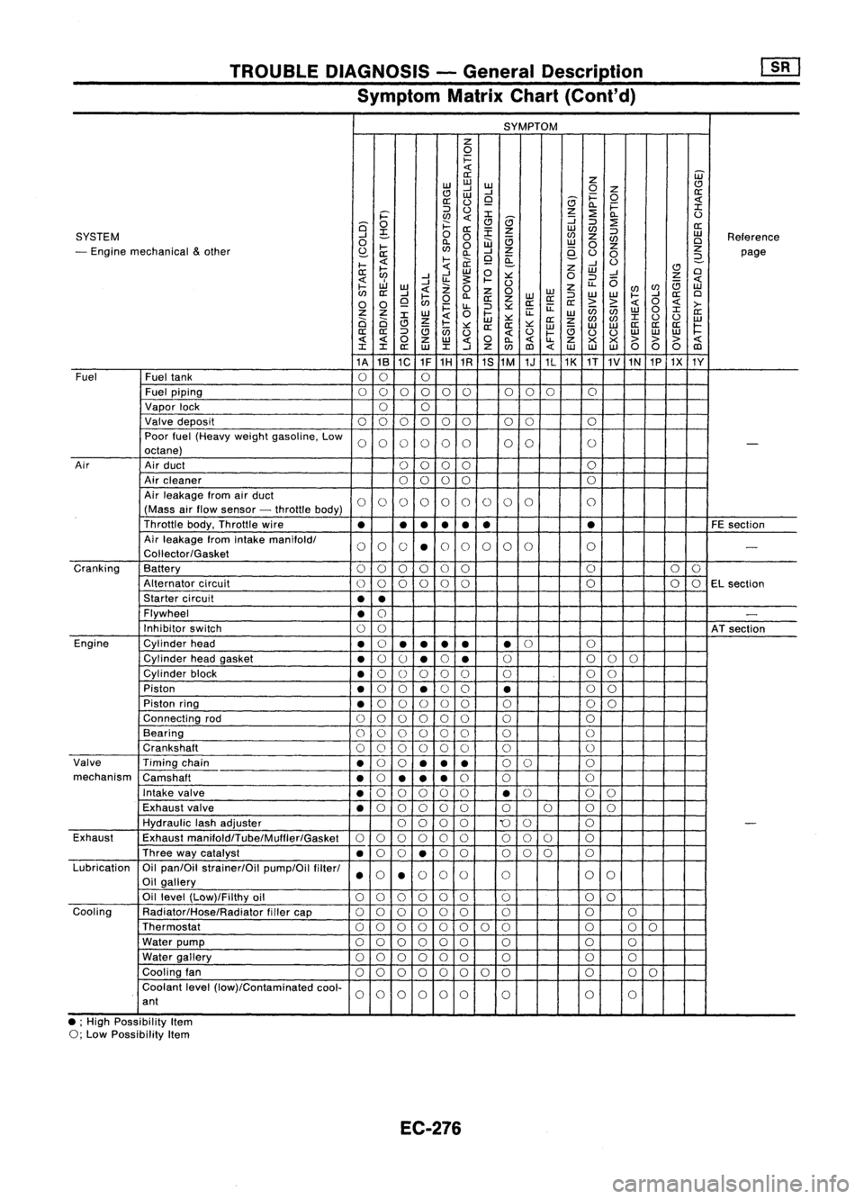
Fuel Fueltank
00 0
Fuel piping
00 0000 000
0
Vapor lock
00
Valve deposit
000 000 00 0
Poor fuel(Heavy weightgasoline. Low
0000 00 00
0
-
octane)
Air Airduct
00 00 0
Air cleaner
0
0
00 0
Air leakage fromairduct
00 00 00 0
0 0
0
(Mass airflow sensor -throttle body)
Throttle body.Throttle wire
•
•
•
•
• •
•
FE
section
Air leakage fromintake
manifoldl
00 0
•
0
0 0
00 0
-
Coliector/Gasket
Cranking Battery
0
0
00 0
0 0
0
0
Alternator circuit
00
00
0
0 0
00
EL
section
Starter circuit
••
Flywheel
•
0
-
Inhibitor switch
00
ATsection
Engine Cylinderhead
•
0
•
•
••
•
0
0
Cylinder headgasket
•
0
()
•
0
•
0
0
00
Cylinder block
•
0
()
0 00 0 00
Piston
•
0
0
•
0
0
•
0
0
Piston ring
•
0
00 0
0 0 00
Connecting rod
00 00
00 0 0
Bearing
000 000 0
0
Crankshaft
00
0 0
0
0 0
0
Valve Timingchain
•
0
0
••
•
0
0 0
mechanism Camshaft
•
0
•• •
0
0 0
Intake valve
•
0
00 0
0
•
0
0
0
Exhaust valve
•
0
00 00 0000
Hydraulic lashadjuster
0000
'0
0 0
-
Exhaust Exhaust
manifoldlTube/Mulfler/Gasket
00
00 0
0
00
0 0
Three waycatalyst
•
0
0
•
0
0 000 0
Lubrication Oilpan/Oil strainer/Oil pump/Oilfilterl
000
0
0 0
0
Oil gallery
••
Oil level (Low)/Filthy oil
00 0000
0 0
0
Cooling Radiator/Hose/Radiator fillercap
00
0 00
0 0 00
Thermostat
00
00 0
0 00 0
00
Water pump
000 000 0 0
0
Water gallery
00 00 00
0 0
0
Cooling fan
00 0
00
0 0
0 0
0
0
Coolant level(low)/Contaminated cool-
00
0000
0 0
0
ant
• ;High Possibility Item
0; Low Possibility Item
EC-276
Page 997 of 1701
![NISSAN ALMERA N15 1995 Service Manual TROUBLEDIAGNOSIS -General Description
[]K]
CONSULT Reference ValueinData Monitor
Mode (Cont'd)
MONITOR ITEM
CONDITION SPECIFICATION
Steering wheelinneutral
position OFF
PW/ST SIGNAL
•Engine: NISSAN ALMERA N15 1995 Service Manual TROUBLEDIAGNOSIS -General Description
[]K]
CONSULT Reference ValueinData Monitor
Mode (Cont'd)
MONITOR ITEM
CONDITION SPECIFICATION
Steering wheelinneutral
position OFF
PW/ST SIGNAL
•Engine:](/manual-img/5/57349/w960_57349-996.png)
TROUBLEDIAGNOSIS -General Description
[]K]
CONSULT Reference ValueinData Monitor
Mode (Cont'd)
MONITOR ITEM
CONDITION SPECIFICATION
Steering wheelinneutral
position OFF
PW/ST SIGNAL
•Engine: Afterwarming up,idle theengine (forward
direction)
The steering wheelis
ON
turned
• Engine: Afterwarming up
Idle2.5-3.7 msec .
INJ PULSE •
Air conditioner switch:OFF
• Shift lever: "N"
• No-load 2,000
rpm 1.9-2.8 msec .
Idle 13-15° BTDC
IGN TIMING
ditto
2,000rpm Morethan25°BTDC
Idle 20-40%
IACV-AACIV ditto
2,000rpm
-
A/F ALPHA •Engine: Afterwarming up Maintaining
enginespeed
53-155%
at 2.000 rpm
AIR COND RLY •Air conditioner switch:OFF
-+
ON OFF
-+
ON
• Ignition switchis~urned toON (Operates for5seconds)
• Engine running andcranking ON
FUEL PUMP RLY
•When engine isstopped (stopsin1.0 seconds)
• Except asshown above OFF
Engine coolant temperature
is 94°C (201°F) orless for
AfT models. and99°C OFF
(210°F) orless for
M/T
mod-
els
• After warming upengine. idletheengine. Engine
coolant temperature
is between 95°C(203°F) and
COOLING FAN •Air conditioner switch:OFF
104°C(219°F) forA/T mod- LOW
• Vehicle stopped
elsonly
Engine coolant temperature
is 105°C (221°F) ormore for
A/T
models. and100°C HIGH
(212°F) ormore for
M/T
models
• Engine: Afterwarming up
IdleON
EGRC SOLIV •
Air conditioner switch:OFF
• Shift lever: "N"
• No-load 2.000
rpm OFF
EC-278
Page 1002 of 1701
TROUBLEDIAGNOSIS -General Description
[ill
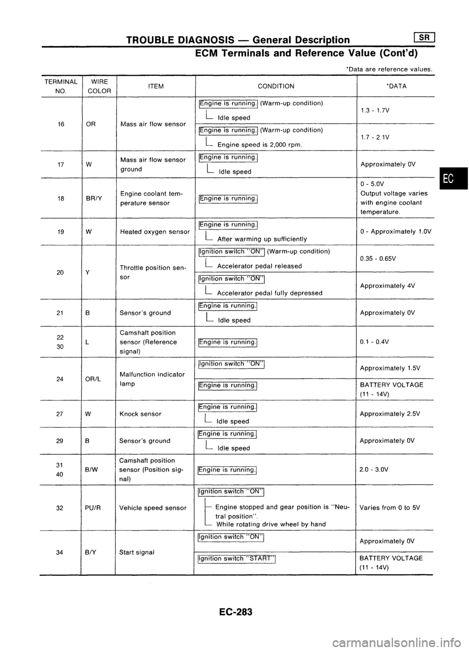
ECM Terminals andReference Value(Conl'd)
*Data arereference values.
TERMINAL WIRE
NO. COLOR ITEM
CONDITION *DATA
IEngine isrunning.1 (Warm-up condition)
1.3-1.7V
L
Idle speed
16 OR Mass
airflow sensor
IEngineisrunning.1 (Warm-up condition)
1.7-2.1V
L
Engine speedis2,000 rpm.
17 W Mass
airflow sensor IEngine
isrunning.!
ApproximatelyOV
ground
L
Idle speed
0-5.0V
18 BRIY Engine
coolant tem-
IEngineisrunning.! Output
voltage varies
perature sensor with
engine coolant
temperature.
19 W
Heatedoxygen sensor IEngine
isrunning.1
0-Approximately 1.OV
L
After warming upsufficiently
Ilgnition switch"ON"I(Warm-up condition)
0.35-0.65V
Throttle position sen-
L
Accelerator pedalreleased
20 Y
sor Ilgnitionswitch"ON"I
L
Approximately
4V
Accelerator pedalfullydepressed
21 B Sensor'sground IEngine
isrunning.1
ApproximatelyOV
L
Idle speed
22 Camshaft
position
30 L
sensor
(Reference IEngineisrunning.1 0.1
-O.4V
signal)
jlgnitionswitch"ON"!
Approximately1.5V
24 ORIL Malfunction
indicator
lamp IEngineisrunning.1 BATTERY
VOLTAGE
(11 -14V)
27 W Knock
sensor IEngine
isrunning.1
Approximately2.5V
L
Idle speed
29 B Sensor's
ground IEngine
isrunning.1
ApproximatelyOV
L
Idle speed
31 Camshaft
position
40
S/W
sensor
(Position sig-
IEngineisrunning.! 2.0
-3.0V
nal)
Ilgnitionswitch"ON"I
32 PUIR
Vehiclespeedsensor
t
Eng;ne "opped andge., po,;!;on ;,"Neo-
Variesfrom0to 5V
tral position".
While rotating drivewheel byhand
Ilgnition switch"ON"!
ApproximatelyOV
34
BIY
Start
signal
Ilgnitionswitch"START"I SA
TTERY VOLTAGE
(11 -14V)
EC-283
•
Page 1016 of 1701
TROUBLEDIAGNOSIS FOROTC13
20
19
6
9
4
~ 2
~ 1.0
1ij
0.8
'w
8!
04
0.2
0.1
.20 020 40 6080100
(-4) (32) (68)(104)(140)(176)(212)
Temperature 'C
(OF)
SEF594K
SEF012P Engine
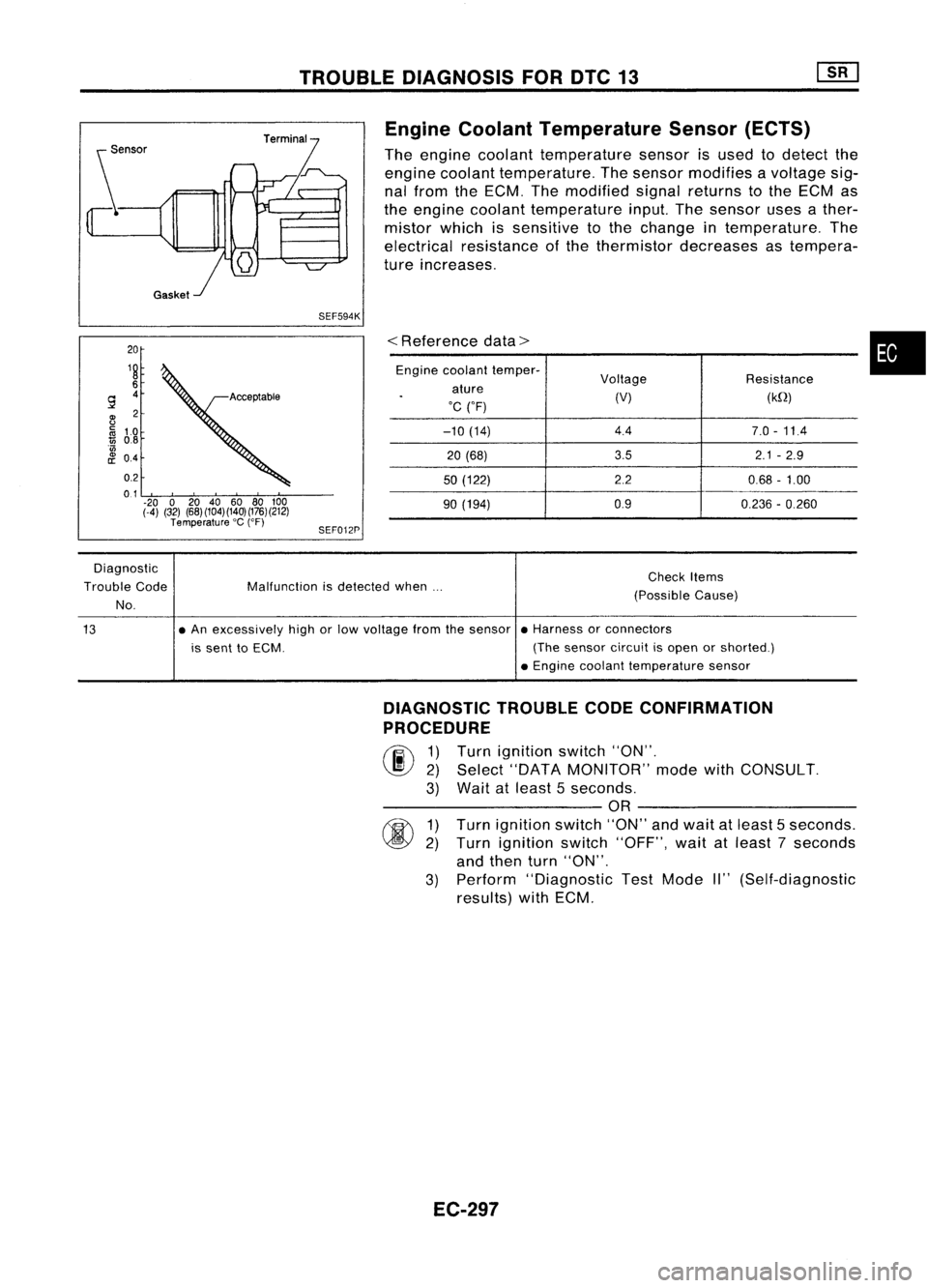
Coolant Temperature Sensor(ECTS)
The engine coolant temperature sensorisused todetect the
engine coolant temperature. Thesensor modifies avoltage sig-
nal from theECM. Themodified signalreturns tothe ECM as
the engine coolant temperature input.Thesensor usesather-
mistor whichissensitive tothe change intemperature. The
electrical resistance ofthe thermistor decreases astempera-
ture increases.
<
Reference data>
Engine coolant temper-
Voltage Resistance
ature
.
(V)(kQ)
'C ("F)
-10 (14) 4.4
7.0-11.4
20 (68) 3.5
2.1-2.9
50 (122) 2.20.68-1.00
90 (194) 0.9
0.236-0.260
•
Diagnostic
Trouble Code
No. Malfunction
isdetected when... Check
Items
(Possible Cause)
13 •
An excessively highorlow voltage fromthesensor •Harness orconnectors
is sent toECM. (Thesensor circuitisopen orshorted.)
• Engine coolant temperature sensor
DIAGNOSTIC TROUBLECODECONFIRMATION
PROCEDURE
rF.i\
1)Turn ignition switch"ON".
~ 2)Select "DATA MONITOR" modewithCONSULT.
3) Wait atleast 5seconds.
---------- OR----------
rm
1)Turn ignition switch"ON"andwait atleast 5seconds.
~ 2)Turn ignition switch"OFF", waitatleast 7seconds
and then turn"ON".
3) Perform "Diagnostic TestMode II"(Self-diagnostic
results) withECM.
EC-297
Page 1017 of 1701
![NISSAN ALMERA N15 1995 Service Manual TROUBLEDIAGNOSIS FORDTC13 ~
Engine Coolant Temperature Sensor(ECTS)
(Cont'd)
EC-ECTS-01
~ENGlNE COOLANT
TEMPERATURE
SENSOR
@lID
Il:j.JJ
4=U
BR/Y B
I I
BR/Y ~ B
$--1--$
BR/Y
U])
B _.
D NISSAN ALMERA N15 1995 Service Manual TROUBLEDIAGNOSIS FORDTC13 ~
Engine Coolant Temperature Sensor(ECTS)
(Cont'd)
EC-ECTS-01
~ENGlNE COOLANT
TEMPERATURE
SENSOR
@lID
Il:j.JJ
4=U
BR/Y B
I I
BR/Y ~ B
$--1--$
BR/Y
U])
B _.
D](/manual-img/5/57349/w960_57349-1016.png)
TROUBLEDIAGNOSIS FORDTC13 ~
Engine Coolant Temperature Sensor(ECTS)
(Cont'd)
EC-ECTS-01
~ENGlNE COOLANT
TEMPERATURE
SENSOR
@lID
Il:j.JJ
4=U
BR/Y B
I I
BR/Y ~ B
$--1--$
BR/Y
U])
B _.
Detectable line
for DTC
-: Non-detectable
line forDTC
~~
@
L
~
~ GY
•
t
BR/Y
B
B
Ii1'sH
~
12-91
TW GND
GND
ECM
-A -A
(ECCS
CONTROL
MODULE)
em
em
L
EC-298 HEC005
Page 1018 of 1701
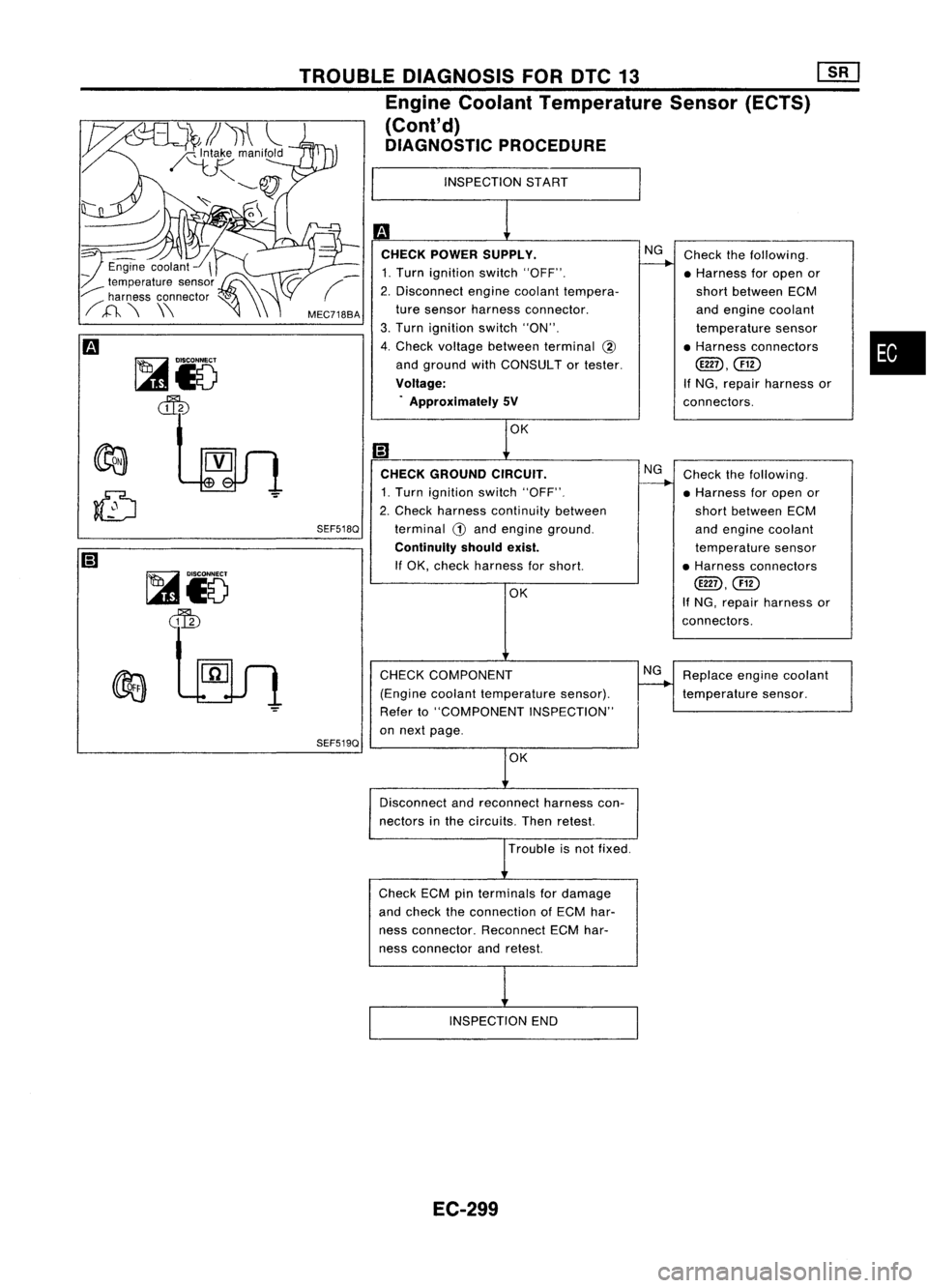
•
Check
thefollowing.
• Harness foropen or
short between ECM
and engine coolant
temperature sensor
• Harness connectors
@D,@)
If NG, repair harness or
connectors.
Replace enginecoolant
temperature sensor.
Check
thefollowing.
• Harness foropen or
short between ECM
and engine coolant
temperature sensor
• Harness connectors
@D.@)
If NG. repair harness or
connectors.
NG
NG
OK
CHECK COMPONENT
(Engine coolanttemperature sensor).
Refer to"COMPONENT INSPECTION"
on next page.
CHECK
GROUND CIRCUIT.
1. Turn ignition switch"OFF".
2. Check harness continuity between
terminal
CD
and engine ground.
Continuity shouldexist.
If OK, check harness forshort.
INSPECTION
START
OK
m
CHECK POWER SUPPLY.
1. Turn ignition switch"OFF".
2. Disconnect enginecoolant tempera-
ture sensor harness connector.
3. Turn ignition switch"ON".
4. Check voltage between terminal
@
and ground withCONSULT ortester.
Voltage: . Approximately 5V
SEF518Q
SEF519Q
MEC7188A
TROUBLE
DIAGNOSIS FORDTC13
mJ
Engine Coolant Temperature Sensor(ECTS)
(Cont'd)
DIAGNOSTIC PROCEDURE
~i5
~
~io
~
Disconnectandreconnect harnesscon-
nectors inthe circuits. Thenretest.
Trouble isnot fixed.
Check ECMpinterminals fordamage
and check theconnection ofECM har-
ness connector. ReconnectECMhar-
ness connector andretest.
INSPECTION END
EC-299