1995 NISSAN ALMERA N15 engine coolant
[x] Cancel search: engine coolantPage 843 of 1701
TROUBLEDIAGNOSIS FOROTC41
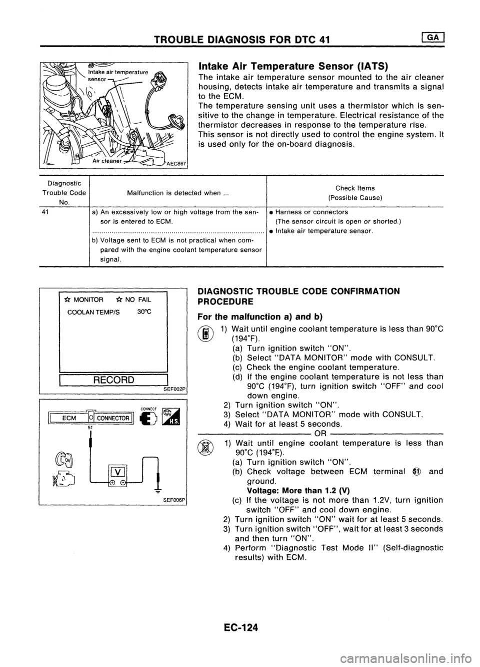
Intake AirTemperature Sensor(IATS)
The intake airtemperature sensormounted tothe aircleaner
housing, detectsintakeairtemperature andtransmits asignal
to the ECM.
The temperature sensingunituses athermistor whichissen-
sitive tothe change intemperature. Electricalresistance ofthe
thermistor decreases inresponse tothe temperature rise.
This sensor isnot directly usedtocontrol theengine system. It
is used onlyforthe on-board diagnosis.
Diagnostic
Trouble Code
No.
41
Malfunction
isdetected when...
a) An excessively loworhigh voltage fromthesen-
sor isentered toECM.
b) Voltage senttoECM isnot practical whencom-
pared withtheengine coolant temperature sensor
signal. Check
Items
(Possible Cause)
• Harness orconnectors
(The sensor circuitisopen orshorted.)
• Intake airtemperature sensor.
*
MONITOR
*
NO FAIL
COOLAN TEMP/S 30°C
RECORD
I
SEF002P
CONNECT ~
II
ECM
a
CONNECTOR
II
I) ~
51
SEF006PDIAGNOSTIC
TROUBLECODECONFIRMATION
PROCEDURE
For themalfunction a)and b)
fF.I\
1)Wait untilengine coolant temperature isless than 90°C
~ (194°F).
(a) Turn ignition switch"ON".
(b) Select "DATA MONITOR" modewithCONSULT.
(c) Check theengine coolant temperature.
(d) Ifthe engine coolant temperature isnot less than
90°C (194°F), turnignition switch"OFF"andcool
down engine.
2) Turn ignition switch"ON".
3) Select "DATA MONITOR" modewithCONSULT.
4) Wait foratleast 5seconds.
---------OR ---------
~ 1)Wait untilengine coolant temperature isless than
~ 90°C(194°F.).
(a) Turn ignition switch"ON".
(b) Check voltage between ECMterminal
@
and
ground.
Voltage: Morethan1.2(V)
(c) Ifthe voltage isnot more than1.2V, turnignition
switch "OFF"andcool down engine.
2) Turn ignition switch"ON"waitforatleast 5seconds.
3) Turn ignition switch"OFF", waitforatleast 3seconds
and then turn"ON".
4) Perform "Diagnostic TestMode II"(Self-diagnostic
results) withECM.
EC-124
Page 869 of 1701
TROUBLEDIAGNOSIS FORNON-DETECTABLE ITEMS
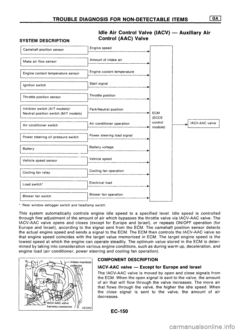
SYSTEM DESCRIPTION Idle
AirControl Valve(IACV) -Auxiliary Air
Control (AAC)Valve
Camshaft positionsensor Engine
speed
I
Mass
airflow sensor Amount
ofintake air
I
Engine coolant temperature sensor Engine
coolant temperature
~
I
Ignition switch Start
signal
I
Throttle positionsensor Throttle
position
~
I
Inhibitor switch(A/Tmodels)/
Park/Neutralposition
Neutral position switch(M/Tmodels) ECM
(ECCS
Air conditioner operation control
!
IACV-AAC valve
I
Air conditioner switch
module)
Power steering oilpressure switch Power
steering loadsignal
I
Battery
~
Battery voltage
Vehicle speedsensor Vehicle
speed
Cooling fanrelay Cooling
fanoperation
Load switch' Electrical
load
Blower fanswitch Blower
fanoperation
': Rear window defogger switchandheadlamp switch.
This system automatically controlsengineidlespeed toaspecified level.Idlespeed iscontrolled
through fineadjustment ofthe amount ofair which bypasses thethrottle valveviaIACV-AAC valve.The
IACV-AAC valveopens andcloses (except forEurope andIsrael), orrepeats ON/OFF operation (for
Europe andIsrael), according tothe signal sentfrom theECM. Thecamshaft positionsensordetects
the actual engine speedandsends asignal tothe ECM. TheECM thencontrols theIACV-AAC valveso
that engine speedcoincides withthetarget valuememorized inECM. Thetarget engine speedisthe
lowest speedatwhich theengine canoperate steadily. Theoptimum valuestored inthe ECM isdeter-
mined bytaking intoconsideration variousengineconditions, suchasduring warmup,deceleration, and
engine load(airconditioner, powersteering andcooling fanoperation).
COMPONENT DESCRIPTION
IACV-AAC valve-Except forEurope andIsrael
The IACV-AAC valveismoved byopen andclose signals from
the ECM. When theopen signal issent tothe valve, theamount
of air that willflow through thevalve increases. Themore air
that flows through thevalve, thehigher theidle speed. When
the close signal issent tothe valve. theamount ofair
decreases.
EC-150
Page 875 of 1701
TROUBLEDIAGNOSIS FORNON-DETECTABLE ITEMS
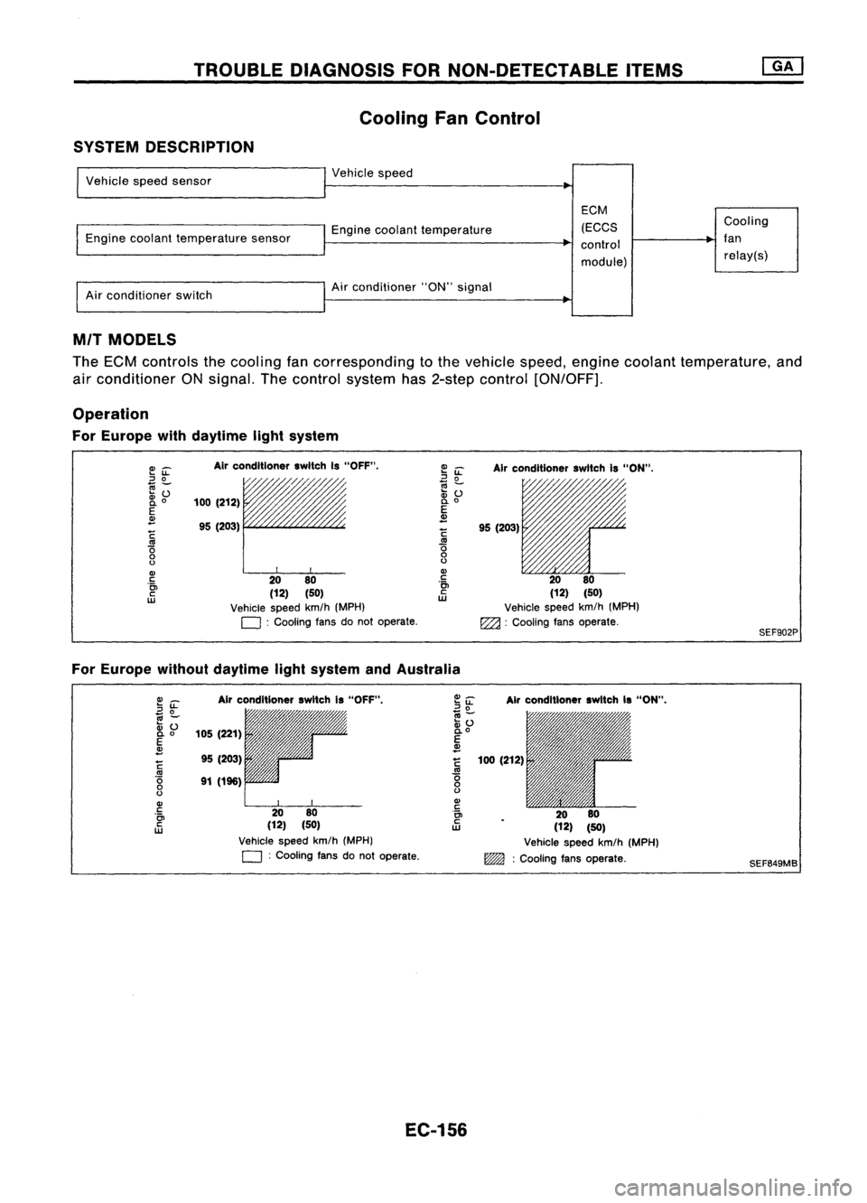
Cooling FanControl
SYSTEM DESCRIPTION
Vehicle speedsensor
Engine coolant temperature sensor
Air conditioner switch Vehicle
speed
Engine coolant temperature
Air conditioner "ON"signal
EGM
(EGGS
control
module) Gooling
fan relay(s)
MIT MODELS
The ECM controls thecooling fancorresponding tothe vehicle speed,engine coolant temperature, and
air conditioner ONsignal. Thecontrol system has2-step control [ON/OFF].
Operation
For Europe withdaytime lightsystem
E~
::J
0
~Z;
2i
o
E
~
~
'0
o
o
Gl
c
'0>
c
w
Air
conditioner switchIs"OFF".
/,
100 (212)
95 (203)
rr
20 80
(12) (50)
Vehicle speedkm/h(MPH)
D :
Cooling fansdonot operate.
~
iL
Airconditioner switchIs"ON".
~ ~ 11'l1/1~~~
:v
() /'/"
0.
0
E
~
!
95(203)
.~ 2080
ill
(12)(50)
Vehicle speedkm/h(MPH)
EZ2l :
Cooling fansoperate.
SEF902P
For Europe withoutdaytime lightsystem andAustralia
Gl_
2~
.,
-
:v ()
0.0
E
~
~
'0
o
o
Gl
c
'0>
c
w
Air
conditioner switchIs"OFF",
105 (221)
95 (203)
91 (196)
2080
(12) (50)
Vehicle speedkm/h(MPH)
D :
Cooling fansdonot operate.
Air
conditioner switchIs"ON",
100 (212)
2080
(12) (50)
Vehicle speedkm/h(MPH)
~ :Cooling fansoperate.
SEF649MB
EC-156
Page 876 of 1701
TROUBLEDIAGNOSIS FORNON-DETECTABLE ITEMS
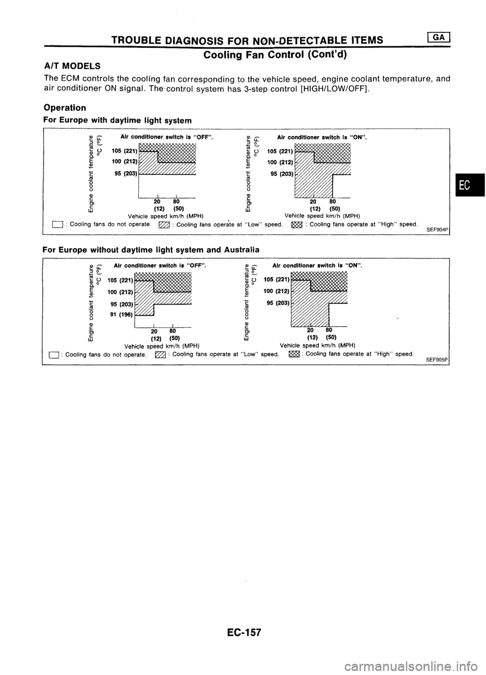
Cooling FanControl (Cont'd)
AIT MODELS
The ECM controls thecooling fancorresponding tothevehicle speed,engine coolant temperature, and
air conditioner ONsignal. Thecontrol system has3-step control
[HIGH/LOW/OFF],
Operation
For Europe withdaytime lightsystem
•
SEF904P
Air
conditioner switchIs"ON".
105 (221)
100 (212)
95 (203)
Air
conditioner switchIs"OFF".
95 (203)
105
(221)
100 (212)
C
'0
o
()
Q)
c
'0>
c
UJ
~
iL
::J
0
e;-
~o
E
~
C
'0
o
()
Q)
~ 00
i~
00
(12) (50)
tD
(12)(50)
Vehicle speedkm/h(MPH) Vehiclespeedkm/h(MPH)
o :
Cooling fansdonot operate. ~:Cooling fansoperate at"Low" speed. ~:Cooling fansoperate at"High" speed.
For Europe withoutdaytime lightsystem andAustralia
SEF905P
Air
conditioner switchis"ON",
105 (221)
100 (212)
95 (203)
Air
conditioner switchIs"OFF".
95 (203)
91 (196)
105
(221)
100 (212)
~
'0
o
()
Q)
c
'0>
c
UJ
~~
::J
0
(;j-
.... 0
~o
E
2
C
'0
o
()
Q)
~ 00
i~
00
(12) (50)
tD
(12)(50)
Vehicle speedkm/h(MPH) Vehiclespeedkm/h(MPH)
o :
Cooling fansdonot operate.
l22a:
Cooling fansoperate at"Low" speed. ~:Cooling fansoperate at"High" speed.
EC-157
Page 881 of 1701
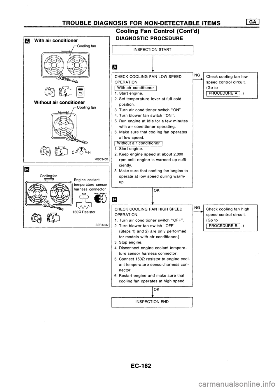
Checkcooling fanlow
speed control circuit.
(Go to
I
PROCEDURE A
I.)
Check cooling fanhigh
speed control circuit.
(Go to
I
PROCEDURE B
I.)
NG
NG
OK
INSPECTION
START
CHECK COOLING FANLOW SPEED
OPERATION.
I
With airconditioner
I
1. Start engine.
2. Set temperature leveratfull cold
position.
3. Turn airconditioner switch"ON".
4. Turn blower fanswitch "ON".
5. Run engine atidle forafew minutes
with airconditioner operating.
6. Make surethatcooling fanoperates
at low speed.
I
Without airconditioner
I
1. Start engine.
2. Keep engine speedatabout 2,000
rpm until engine iswarmed upsuffi-
ciently.
3. Make surethatcooling fanbegins to
operate atlow speed during warm-
up.
MEC340B
TROUBLE
DIAGNOSIS FORNON-DETECTABLE ITEMS
Cooling FanControl (Cant'd)
DIAGNOSTIC PROCEDURE
Cooling fan
Without
airconditioner
Coolingfan
Engine coolant
~ ~ ~a~~:;:t:a::;'~~'
~~ eN
lDoo
Q
CHECKCOOLING FANHIGH SPEED
150n
Resistor
~ ~ OPERATION.
~ ~ 1.Turn airconditioner switch"OFF".
SEF492Q
2.Turn blower fanswitch "OFF".
(Steps 1)and 2)are only performed
for models withairconditioner.)
3. Stop engine.
4. Disconnect enginecoolant tempera-
ture sensor harness connector.
5.
Connect
1500
resistor toengine cool-
ant temperature sensor.harness con-
nector.
6. Restart engineandmake surethat
cooling fanoperates athigh speed.
m
With airconditioner
Coolingfan
OK
INSPECTION END
EC-162
Page 885 of 1701
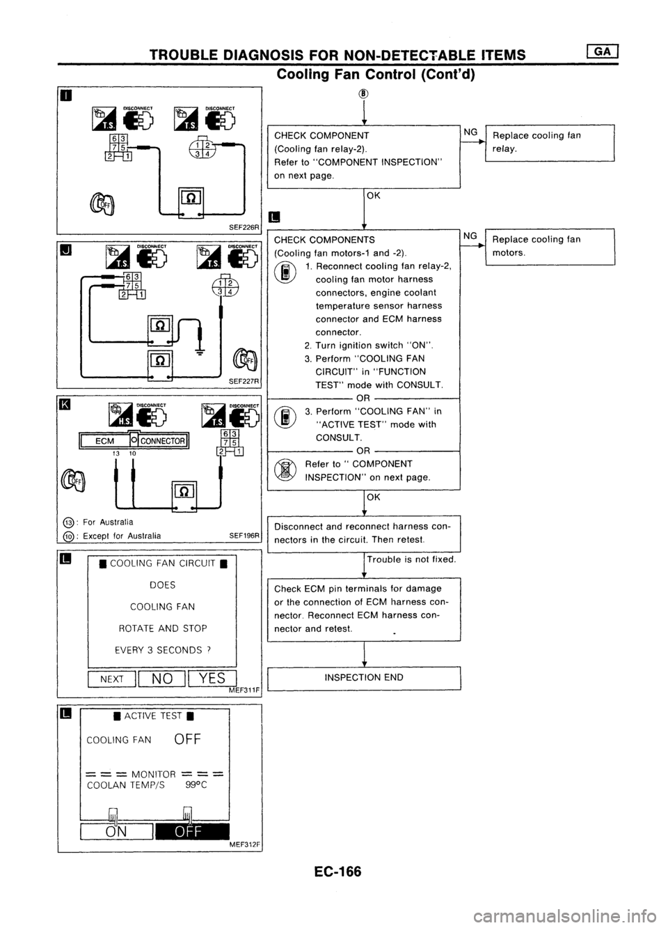
TROUBLEDIAGNOSIS FORNON-DETECTABLE ITEMS
Cooling FanControl (Cont'd)
@
o
~i5
~-
m=m
CHECK
COMPONENT
(Cooling fanrelay-2).
Refer to"COMPONENT INSPECTION"
on next page.
NG
Replace coolingfan
relay.
OK
II
Replacecoolingfan
motors.
NG
OK
SEF226R
SEF227R
~i5
00
Jm1
3
7 5
2 1
CHECK
COMPONENTS
~ IDlsco~
(Coolingfanmotors-1 and-2).
I...s1
0~
1.Rec~nnect coolingfanrelay-2,
~ \J!}
coolingfanmotor harness
QW
connectors,enginecoolant
temperature sensorharness
connector andECM harness
connector.
2. Turn ignition switch"ON".
3. Perform "COOLING FAN
CIRCUIT" in"FUNCTION
TEST" modewithCONSULT.
OR
3. Perform "COOLING FAN"in
"ACTIVE TEST"modewith
CONSULT.
OR
~ Referto"COMPONENT
~ INSPECTION" onnext page.
~i5
:~
rn=m
~i5
ECM
El'CONNECTORII
13 10
II
@:
ForAustralia
@:
Except forAustralia SEF196R
Disconnect
andreconnect harnesscon-
nectors inthe circuit. Thenretest.
II
•COOLING FANCIRCUIT.
DOES
COOLING FAN
ROTATE ANDSTOP
Trouble
isnot fixed .
Check ECMpinterminals fordamage
or the connection ofECM harness con-
nector. Reconnect ECMharness con-
nector andretest.
EVERY 3SECONDS
7
NEXT
II
NO
II
YES
I
MEF311F
INSPECTION
END
II •
ACTIVE TEST.
COOLING FAN
OFF
=
= =
MONITOR
COOLAN TEMPjS
---
---
ggoC
CJ5_N_I~ MEF312F
EC-166
Page 898 of 1701
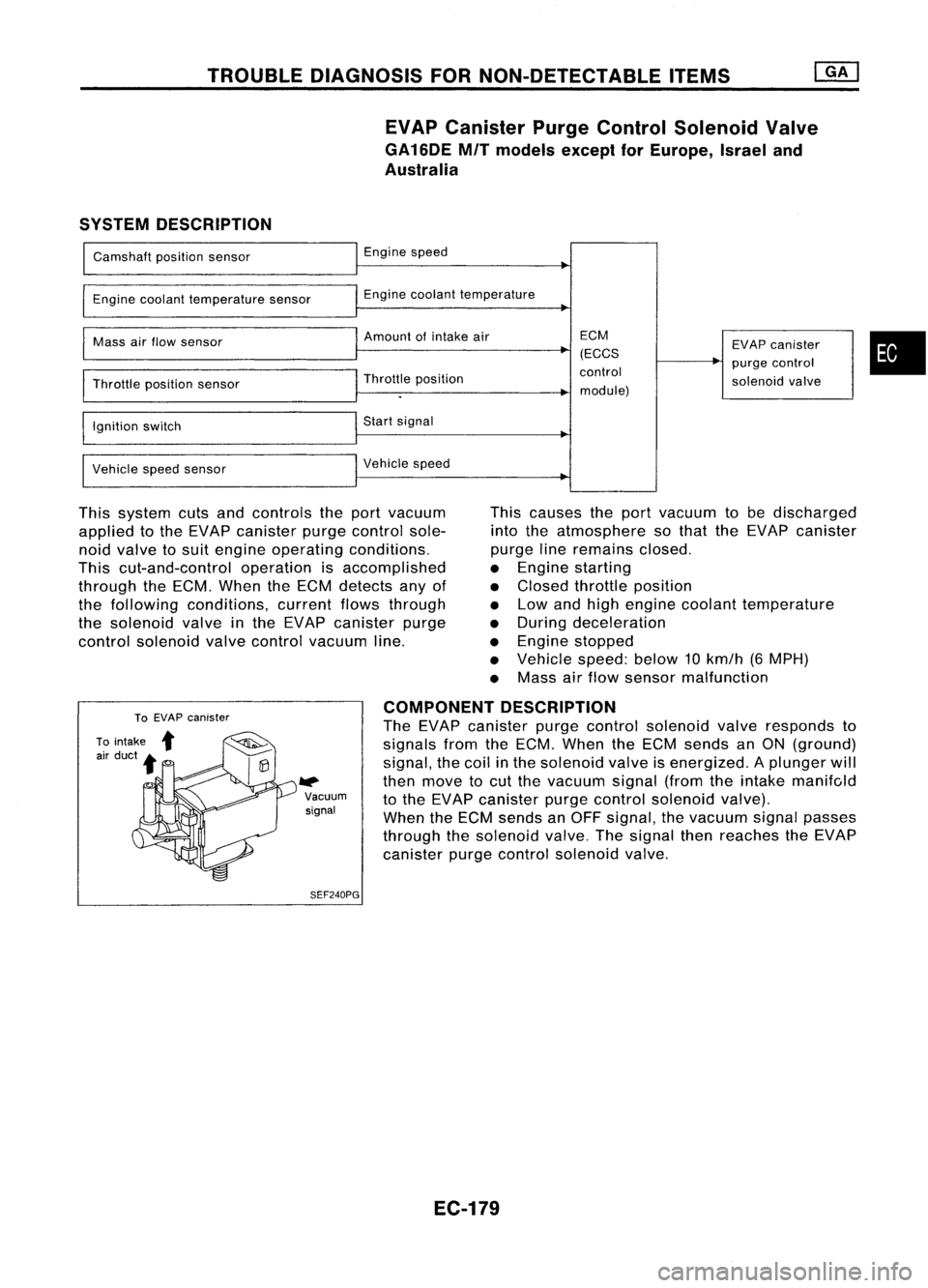
TROUBLEDIAGNOSIS FORNON-DETECTABLE ITEMS
EVAP Canister PurgeControl Solenoid Valve
GA16DE MITmodels exceptforEurope, Israeland
Australia
SYSTEM DESCRIPTION
Camshaft positionsensor
Engine coolant temperature sensor
Mass airflow sensor
Throttle positionsensor
Ignition switch
Vehicle speedsensor Engine
speed
Engine coolant temperature
Amount ofintake air
Throttle position
Start signal
Vehicle speed ECM
(ECCS
control
module) EVAP
canister
purge control
solenoid valve
•
This system cutsandcontrols theport vacuum
applied tothe EVAP canister purgecontrol sole-
noid valve tosuit engine operating conditions.
This cut-and-control operationisaccomplished
through theECM. When theECM detects anyof
the following conditions, currentflowsthrough
the solenoid valveinthe EVAP canister purge
control solenoid valvecontrol vacuum line. This
causes theport vacuum tobe discharged
into theatmosphere sothat theEVAP canister
purge lineremains closed.
• Engine starting
• Closed throttle position
• Low andhigh engine coolant temperature
• During deceleration
• Engine stopped
• Vehicle speed:below10km/h (6MPH)
• Mass airflow sensor malfunction
W>
Vacuum
signal
SEF240PG COMPONENT
DESCRIPTION
The EVAP canister purgecontrol solenoid valveresponds to
signals fromtheECM. When theECM sends anON (ground)
signal, thecoil inthe solenoid valveisenergized. Aplunger will
then move tocut the vacuum signal(fromtheintake manifc,ld
to the EVAP canister purgecontrol solenoid valve).
When theECM sends anOFF signal, thevacuum signalpasses
through thesolenoid valve.Thesignal thenreaches theEVAP
canister purgecontrol solenoid valve.
EC-179
Page 902 of 1701
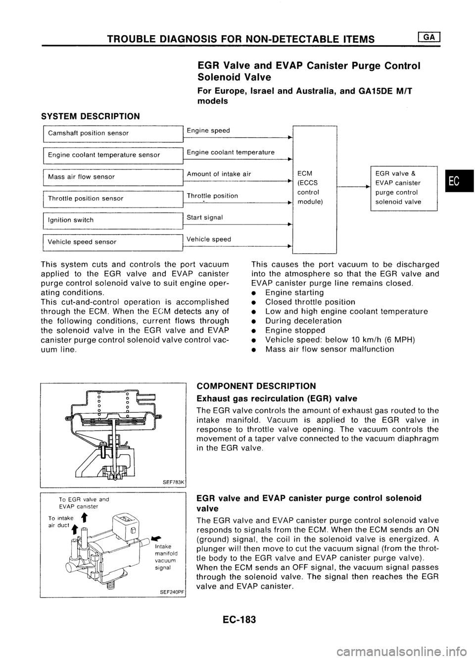
TROUBLEDIAGNOSIS FORNON-DETECTABLE ITEMS
EGR Valve andEVAP Canister PurgeControl
Solenoid Valve
For Europe, IsraelandAustralia, andGA15DE MIT
models
SYSTEM DESCRIPTION
Camshaft positionsensor
Engine coolant temperature sensor
Mass airflow sensor
Throttle position sensor
Ignition switch
Vehicle speedsensor Engine
speed
Engine coolant temperature
Amount ofintake air
Throttle position
Start signal
Vehicle speed ECM
(ECCS
control module) EGR
valve
&
EVAP canister
purge control
solenoid valve
•
This system cutsandcontrols theport vacuum
applied tothe EGR valve andEVAP canister
purge control solenoid valvetosuit engine oper-
ating conditions.
This cut-and-control operationisaccomplished
through theECM. When theECM detects anyof
the following conditions, currentflowsthrough
the solenoid valveinthe EGR valve andEVAP
canister purgecontrol solenoid valvecontrol vac-
uum line. This
causes theport vacuum tobe discharged
into theatmosphere sothat theEGR valve and
EVAP canister purgelineremains closed.
• Engine starting
• Closed throttle position
• Low andhigh engine coolant temperature
• During deceleration
• Engine stopped
• Vehicle speed:below10km/h (6MPH)
• Mass airflow sensor malfunction
SEF783K
l#
Intake
manifold
vacuum signal
SEF240PF COMPONENT
DESCRIPTION
Exhaust gasrecirculation (EGR)valve
The EGR valve controls theamount ofexhaust gasrouted tothe
intake manifold. Vacuumisapplied tothe EGR valve in
response tothrottle valveopening. Thevacuum controls the
movement ofataper valve connected tothe vacuum diaphragm
in the EGR valve.
EGR valve andEVAP canister purgecontrol solenoid
valve
The EGR valve andEVAP canister purgecontrol solenoid valve
responds tosignals fromtheECM. When theECM sends anON
(ground) signal,thecoil inthe solenoid valveisenergized. A
plunger willthen move tocut the vacuum signal(fromthethrot-
tle body tothe EGR valve andEVAP canister purgevalve).
When theECM sends anOFF signal, thevacuum signalpasses
through thesolenoid valve.Thesignal thenreaches theEGR
valve andEVAP canister.
EC-183