Page 792 of 1701
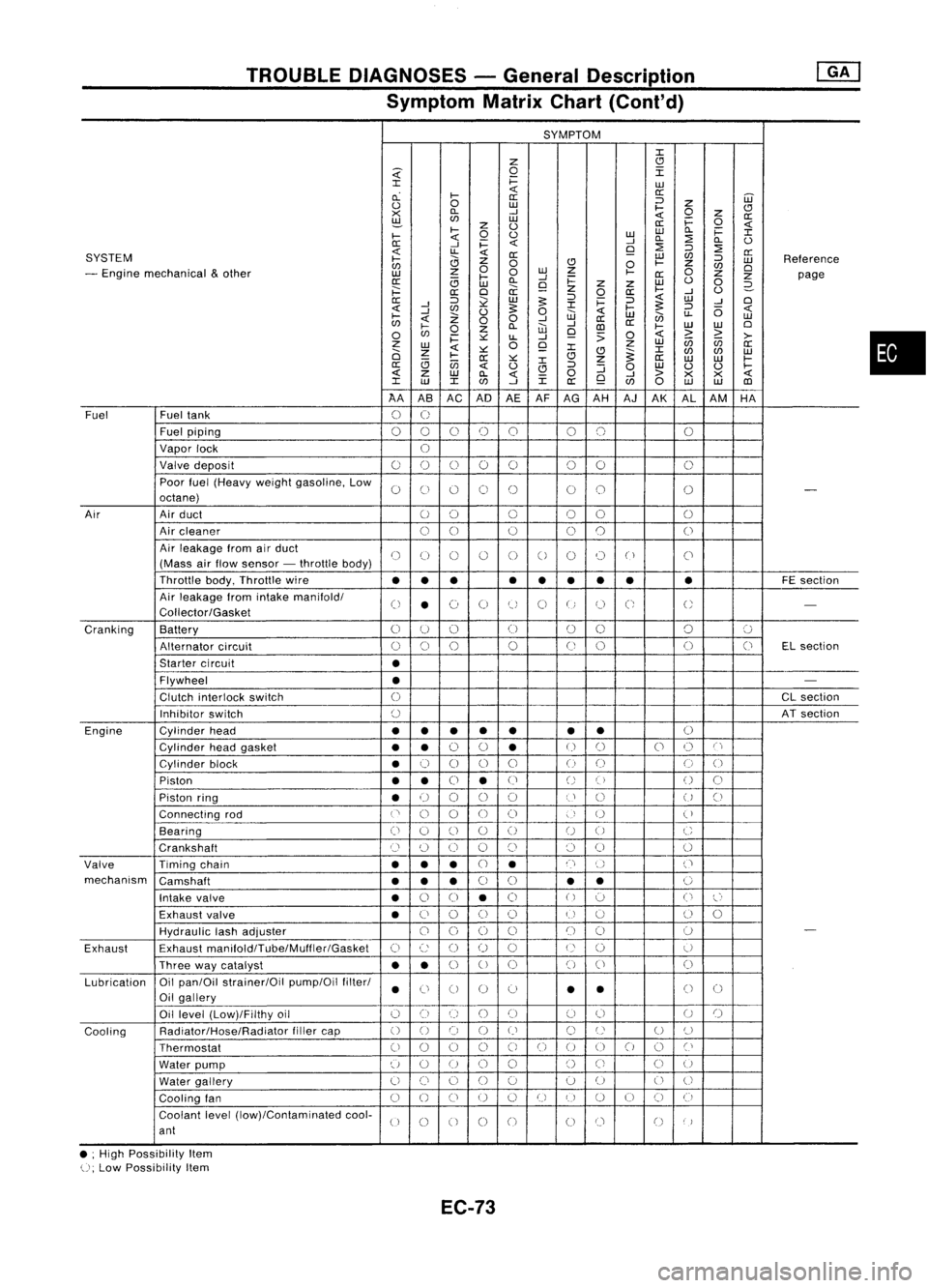
TROUBLEDIAGNOSES -General Description
Symptom MatrixChart(Cont'd)
SYMPTOM
J:
Z
CJ
~
0
I
J:
i=
LU
cL
I-
«
a:
a: ::J
UJ
0
0
LU
I-
Z
CJ
><
D..
-'
«
0
z
a:
~
LU
i=
0
z
0
a:
«
I-
0
0
LULU
D..
i=
J:
I-
«
-'
D..
:2
D..
0
0:
-'
i=
«
9
:2
::J
:2
SYSTEM
«
LL
«
0:
LU
C/J
a:
I-
0
Z
0
CJ
0
I-
Z
::J
LU
Reference
C/J
0
C/J
0
- Engine mechanical
&
other
z
0
LU
Z
I-
0
LU
I-
-'
0:
Z
Z
page
0:
(3
LU
D..
9
i=
z
Z
LU
0
0
2-
;:::
a:
0
a:
z
0
a:
I-
-'
0
0:
::J
~
LU
5:
::J
i=
::J
«
LU
-'
0
-'
J:
5:
«
-'
C/J
0
5:
0
«
I-
::J
(5
«
I-
Z
W
LU
en
LL
LU
C/J
«
00
-'
-'
a:
a:
0
I-
0
Z
D..
W
CD
I-
LU
LU
0
C/J
i=
~
LL
-'
9
:>
0
«
>
~
>-
z
0
Z
LU
(ij
C/J
a:
LU
«
~
9
J:
J:
0
Z
CJ
~
C/J
C/J
LU
I-
0:
~
CJ
Z
a:
LU LU
I-
(3
(jj
J:
a:
«
0
CJ
::J
:J
0
LU
0 0
I-
«
z
LU
D..
«
0
-'
>
><><
«
J:
LU
J:
C/J
-'
J:
a:
9
C/J
0
LU LU
CD
AA ASAC AD
AEAF
AG AH AJAK ALAM HA
Fuel Fueltank
0
U
Fuel piping
00 0
()
0 00 0
Vapor lock
U
Valve deposit
00 000 00
0
Poor fuel(Heavy weightgasoline, Low
0
C)
0 0
()
00
0
-
octane)
Air Airduct
00 0
00
0
Air cleaner
00
0
0
0
0
Air leakage fromairduct
()
(J
()
()
0
0
0 0
("
)
C'
(Mass airflow sensor -throttle body)
Throttle body,Throttle wire
••• •
••
•• •
FE
section
Air leakage fromintake manifold/
0
•
(~)
0
tJ
0
U
C;
U
-
Collector/Gasket
Cranking Battery
0
U
()
(J
00 0
':J
Alternator circuit
()
0
0
0
(J
0 0
(J
ELsection
Starter circuit
•
Flywheel
•
-
Clutch interlock switch
0
CL
section
Inhibitor switch
()
ATsection
Engine Cylinderhead
••
• •
• •
•
()
Cylinder headgasket
••
0
0
•
U
()
0
()
C'
Cylinder block
•
0
0 0
0
()
(J
0
0
Piston
••
0
•
(J
()
()
()
0
Piston ring
•
U
00
0
U
()
U
()
Connecting rod
('
0
0
00
)
U
(
)
Bearing
(i
0
()
0
()
U
0
C
Crankshaft
Cl
(~)
0 0
()
()
0
0
Valve Timingchain
•••
CJ
•
n
()
('
mechanism Camshaft
•••
0
0
•
•
0
Intake valve
•
0
0
•
0
()
':J
0
l~'
Exhaust valve
•
C)
0
()
()
U
u
()
0
HydraUlic lashadjuster
00
0
0
()
()
0
-
Exhaust Exhaust
manifoldlTube/Muffler/Gasket
C)
c:
()
()
0
U
()
U
Three waycatalyst
••
0
U
0 0
()
0
Lubrication Oil
pan/Oil strainer/Oil pump/Oilfilter/
•
Ci
0 0
0
•
•
()
0
Oil gallery
Oil level (Low)/Filthy oil
()
0
()
()()
(J
0
U
()
Cooling Radiator/Hose/Radiator
fillercap
()
0 0
()
()
C)
U
U
()
Thermostat
00
0
0
C)
0
()
00
0
Cl
Water pump
u
0
U
0
0
()
Ci
C)
U
Water gallery
U
()
0
()
0 0
U
0
U
Cooling fan
0
()
CJ
U
0
U
I)
U
()
CJ
(i
Coolant level(low)/Contaminated cool-
U
0
0 0
0
00
()
)
ant
• ;High Possibility Item
U;
Low Possibility Item
EC-73
•
Page 800 of 1701
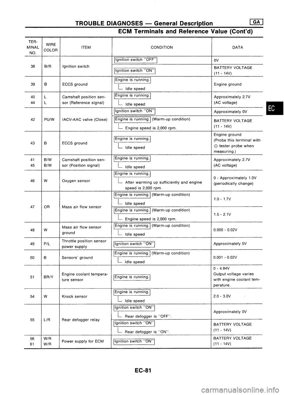
TROUBLEDIAGNOSES -General Description ~
ECM Terminals andReference Value(Cont'd)
TER-
MINAL WIRE
CONDITION
ITEM DATA
NO. COLOR
Ilgnitionswitch"OFF"1
OV
38 BIR
Ignitionswitch
BATTERYVOLTAGE
llgnition switch"ON"!
(11-14V)
39 B ECCSground
I
Engine isrunning.
I
Engineground
L
Idle speed
40 l Camshaft positionsen- I
Engine isrunning. I
Approximately2.7V
44 l sor(Reference signal)
L
Idle speed (AC
voltage)
i'gnition switch"ON'"
ApproximatelyOV
42 PUlW IACV-AAC valve(Close) IEngine
isrunning.
I
(Warm-up condition)
BATTERYVOLTAGE
L
Engine speedis2,000 rpm. (11
-14V)
I
Engine isrunning.
I
Engine
ground
43 B ECCS
ground (Probe
thisterminal with
L
Idle speed
e
tester probe when
measuring.)
41
B/W
Camshaft positionsen- IEngine
isrunning.1
Approximately2.7V
45
B/W
sor
(Position signal)
L
Idle speed (AC
voltage)
I
Engine isrunning.
I
o-
Approximately 1.0V
46 W Oxygen
sensor
L
After warming upsufficiently andengine
(periodicallychange)
speed is2,000 rpm.
I
Engine isrunning.
I
(Warm-up condition)
1.0-1.7V
L
Idle speed
47 OR Massairflow sensor
I
Engine isrunning.! (Warm-up condition)
L
Engine speedis2,000 rpm. 1.5
-2.1V
48 W Mass
airflow sensor
I
Engine isrunning. I(Warm-up condition)
0.005-0.02V
ground
L
Idle speed
49 P/l Throttle
position sensor
j!gnitionswitch"ON"I Approximately
5V
power supply
50 B Sensors'
ground
I
Engine isrunning.
I
(Warm-up condition)
0.001-0.02V
L
Idle speed
0-4.84V
51 BRIY Engine
coolant tempera-
1Engine isrunning.
I
Output
voltage varies
ture sensor with
engine coolant tem-
perature.
54 W Knock
sensor
I
Engine isrunning.!
2.0-3.0V
L
Idle speed
Ilgnition switch"ON'"
ApproximatelyOV
L
Rear defogger is"OFF".
55 LlR Rear
defogger relay
Ilgnitionswitch"ON"I
BATTERY VOLTAGE
L
Rear defogger is"ON". (11
-14V)
56
W/R
Ilgnitionswitch"ON"I BA
TTERY VOLTAGE
61
W/R
Power
supply forECM
(11-14V)
EC-81
•
Page 803 of 1701
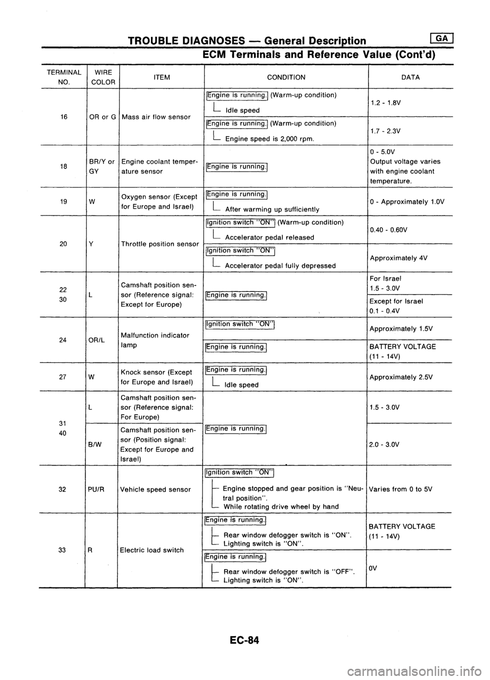
TROUBLEDIAGNOSES -General Description
rnJ
ECM Terminals andReference Value(Cont'd)
TERMINAL WIRE
CONDITION
NO. COLOR ITEM
DATA
IEngine isrunning./ (Warm-up condition)
1.2-1.8V
L
Idle speed
16 ORorG Mass airflow sensor
IEngineisrunning.1 (Warm-up condition)
1.7-2.3V
L
Engine speedis2,000 rpm.
0-5.0V
18 BR/Yor
Enginecoolant temper-
IEngineisrunning.' Output
voltage varies
GY aturesensor with
engine coolant
temperature.
19 W Oxygen
sensor(Except IEngine
isrunning.1
o-
Approximately 1.0V
for Europe andIsrael)
L
After warming upsufficiently
Ilgnition switch"ON"I(Warm-up condition)
0.40-0.60V
L
Accelerator pedalreleased
20 Y Throttlepositionsensor
jlgnitionswitch"ON"I
L
Accelerator pedalfullydepressed Approximately
4V
For Israel
22 Camshaft
positionsen-
1.5-3.0V
30 L
sor(Reference signal:
IEngineisrunning.1
Except forEurope) Except
forIsrael
0.1 -0.4V
Ilgnition switch"ON'"
Approximately1.5V
24 ORIL Malfunction
indicator
lamp IEngineisrunning.1 BATIERY
VOLTAGE
(11 -14V)
27 W Knock
sensor (Except IEngine
isrunning.1
Approximately2.5V
for Europe andIsrael)
L
Idle speed
Camshaft positionsen-
L sor(Reference signal: 1.5-3.0V
For Europe)
31 IEngineisrunning.1
40 Camshaft
positionsen-
B/W
sor
(Position signal:
2.0-3.0V
Except forEurope and
Israel)
Ilgnitionswitch"ON"I
32 PUIR Vehiclespeedsensor
t
Eog'oe stopped aodgea, posit;oo
'S
"Neu- Variesfrom0to 5V
tral position".
While rotating drivewheel byhand
IEngine isrunning.1
BATIERY VOLTAGE
t
Rear window defogger switchis"ON".
(11-14V)
Electric loadswitch Lighting
switchis"ON".
33 R
IEngineisrunning.1
t
Rear window defogger switchis"OFF". OV
Lighting switchis"ON".
EC-84
Page 827 of 1701
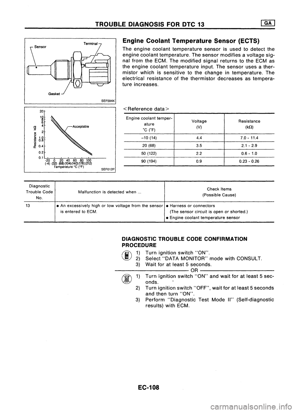
TROUBLEDIAGNOSIS FORDTC13
SEF594K Engine
Coolant Temperature Sensor(ECTS)
The engine coolant temperature sensorisused todetect the
engine coolant temperature. Thesensor modifies avoltage sig-
nal from theECM. Themodified signalreturns tothe ECM as
the engine coolant temperature input.Thesensor usesather-
mistor whichissensitive tothe change intemperature. The
electrical resistance ofthe thermistor decreases astempera-
ture increases.
20
18
6
9 4
B
2
Iii
10
1ii
0.8
'0
£ 0.4
0.2
0.1 -20 020 40 60 80100
(-4) (32) (68)(104)(140)(176)(212)
Temperature 'C
(OF)
SEF012P
<
Reference data>
Engine coolant temper-
Voltage Resistance
ature
'C ('F) (V)
(kQ)
-10 (14) 4.47.0-11.4
20 (68)
3.52.1-2.9
50 (122)
2.20.6-1.0
90 (194) 0.9
0.23-0.26
Diagnostic
Trouble Code
No.
Malfunction
isdetected when... Check
Items
(Possible Cause)
13
•An excessively highorlow voltage fromthesensor •Harness orconnectors
is entered toECM. (Thesensor circuitisopen orshorted.)
• Engine coolant temperature sensor
DIAGNOSTIC TROUBLECODECONFIRMATION
PROCEDURE
(F.i\
1)Turn ignition switch"ON".
~ 2)Select "DATA MONITOR" modewithCONSULT.
3) Wait foratleast 5seconds.
------------OR------------
fU\
1)Turn ignition switch"ON"andwait foratleast 5sec-
~ onds.
2) Turn ignition switch"OFF", waitforatleast 5seconds
and then turn"ON".
3) Perform "Diagnostic TestMode II"(Self-diagnostic
reSUlts) withECM.
EC-108
Page 828 of 1701
TROUBLEDIAGNOSIS FORDTC13 ~
Engine Coolant Temperature Sensor(ECTS)
(Cont'd)
EC-ECTS-01
t
ENGINE
COOLANT
TEMPERATURE
SENSOR
m
@:ForEurope and
Israel
@:
Except@
*1",@ GY@BR!Y
,
-: Detectable line
for DTC
-: Non-detectable
line forDTC
•
lZlfll)
GY
B
~
GND
-A
B
~
GND -A ECM
(ECCSCONTROL
MODULE)
em
HEC032
EC-109
Page 829 of 1701
GA16DE forAustralia TROUBLE
DIAGNOSIS FORDTC13
[]K]
Engine Coolant Temperature Sensor(ECTS)
(Cont'd)
EC-ECTS-01
~ENGINE COOLANT
TEMPERATURE
SENSOR
(ffl)
U:iJ
lbi=ll
BR/Y B
t
-:
-:
Detectable
line
for DTC
Non-detectable line forDTC
~
@
GY
BR/Y
IT5TI
TW
B
115"0
I
GND -A
ECM
(ECCS
CONTROL
MODULE)
em
101 102103
107 108109
113 114115 104
105 106
110 HI H2
116 117118
EC-110 HEC065
Page 830 of 1701
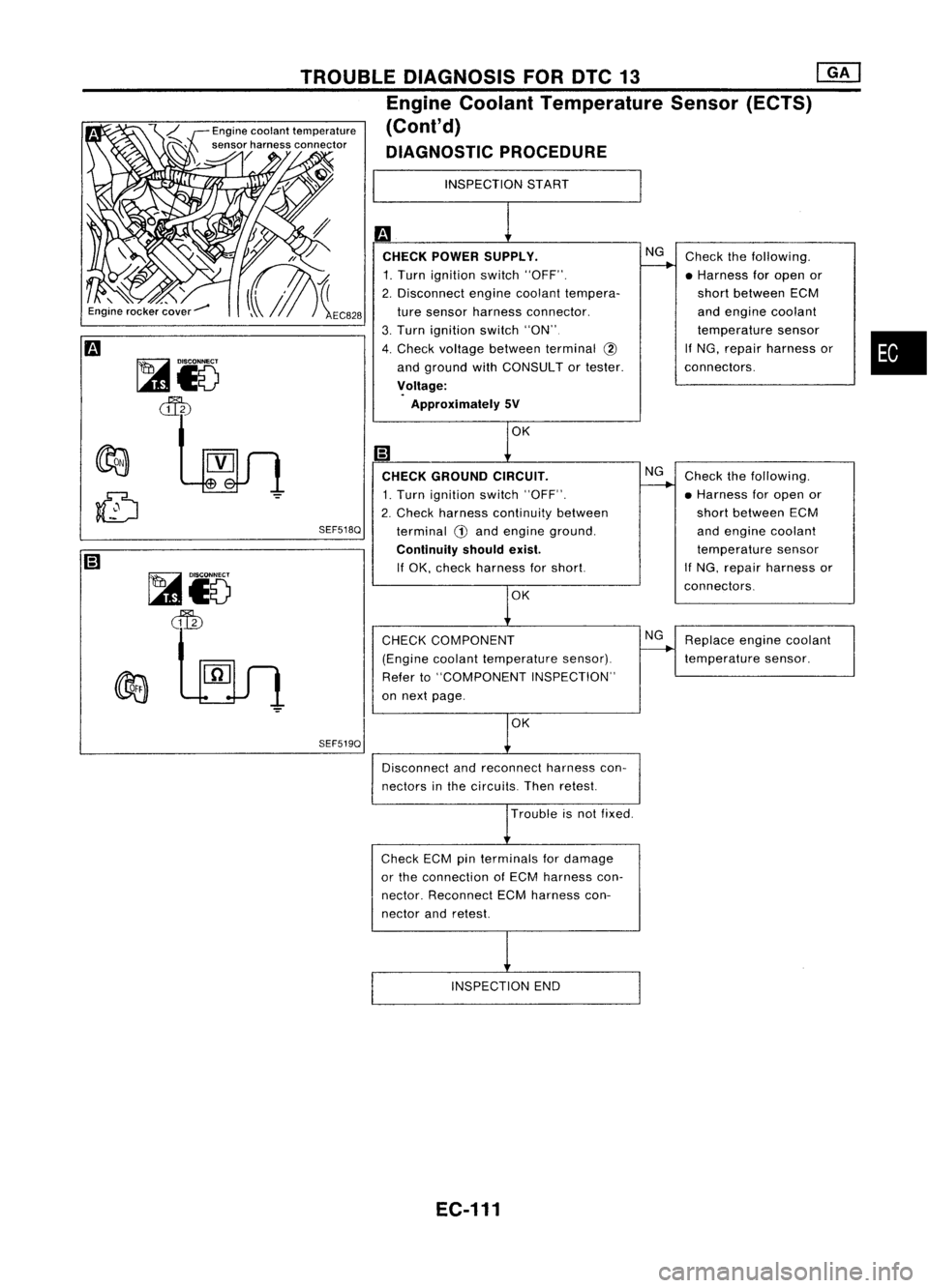
•
Replace enginecoolant
temperature sensor.
Check
thefollowing.
• Harness foropen or
short between ECM
and engine coolant
temperature sensor
If NG, repair harness or
connectors.
Check thefollowing.
• Harness foropen or
short between ECM
and engine coolant
temperature sensor
If NG, repair harness or
connectors.
NG
NG
NG
CHECK COMPONENT
(Engine coolanttemperature sensor).
Refer to"COMPONENT INSPECTION"
on next page.INSPECTION
START
m
CHECK POWER SUPPLY.
1. Turn ignition switch"OFF".
2. Disconnect enginecoolant tempera-
ture sensor harness connector.
3. Turn ignition switch"ON"
4. Check voltage between terminal @
and ground withCONSULT ortester.
~oltage:
Approximately SV
SEF519Q
Ii)
CHECK GROUND CIRCUIT.
1. Turn ignition switch"OFF".
2. Check harness continuity between
SEF518Q
terminal
G)
and engine ground.
Continuity shouldexist.
If OK, check harness forshort.
TROUBLE
DIAGNOSIS FORDTC13 ~
Engine Coolant Temperature Sensor(ECTS)
(Cont'd)
DIAGNOSTIC PROCEDURE
Engine
coolant temperature
sensor harness connector
~/
~Io
ten
~Io
~
Disconnectandreconnect harnesscon-
nectors inthe circuits. Thenretest.
Trouble isnot fixed.
Check ECMpinterminals fordamage
or the connection ofECM harness con-
nector. Reconnect ECMharness con-
nector andretest.
INSPECTION END
EC-111
Page 831 of 1701
TROUBLEDIAGNOSIS FORDTC13 @KJ
Engine Coolant Temperature Sensor(ECTS)
, '(Cont'd)
COMPONENT INSPECTION
Engine coolant temperature sensor
Check resistance asshown inthe figure.
SEF152P Temperature
°C
(OF)
20 (68)
50 (122)
90 (194) Resistance
kQ
2.1 -2.9
0.68 -1.00
0.236 -0.260
If
NG, replace enginecoolant temperature sensor.
EC-112