1995 NISSAN ALMERA N15 engine coolant
[x] Cancel search: engine coolantPage 747 of 1701
ENGINEANDEMISSION BASICCONTROL SYSTEMDESCRIPTION ~
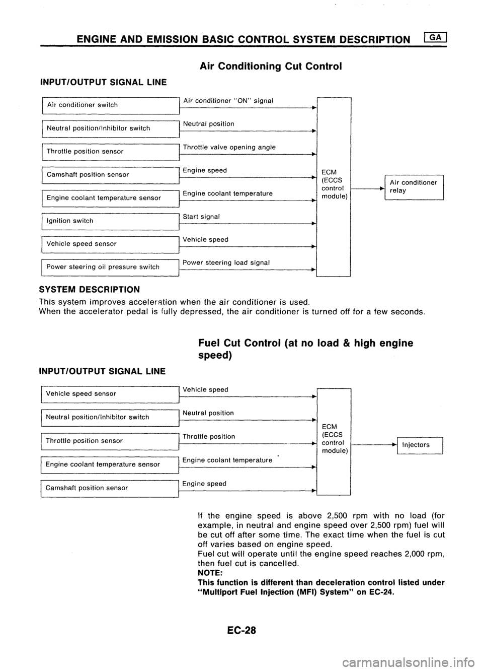
Air Conditioning CutControl
INPUT/OUTPUT SIGNALLINE
Air conditioner switch
Neutral position/Inhibitor switch
Throttle position sensor
Camshaft positionsensor
Engine coolant temperature sensor
Ignition switch
Vehicle speedsensor
Power steering oilpressure switch Air
conditioner "ON"signal
Neutral position
Throttle
valve
opening angle
Engine speed
Engine coolant temperature
Start signal
Vehicle speed
Power steering loadsignal ECM
(ECCS
control
module) Air
conditioner
relay
SYSTEM DESCRIPTION
This system improves acceler8.tion whentheairconditioner isused.
When theaccelerator pedalisfully depressed, theairconditioner isturned offfor afew seconds.
Fuel CutControl (atnoload
&
high engine
speed)
INPUT/OUTPUT SIGNALLINE
Vehicle speedsensor
Neutral position/Inhibitor switchVehicle
speed
Neutral position
Throttle position sensor
Engine coolant temperature sensor
Camshaft positionsensor Throttle
position
Engine coolant temperature
Engine speed ECM
(ECCS
control
module) Injectors
If the engine speedisabove 2,500rpmwith noload (for
example, inneutral andengine speedover2,500 rpm)fuelwill
be cut offafter some time.Theexact timewhen thefuel iscut
off varies basedonengine speed.
Fuel cutwill operate untiltheengine speedreaches 2,000rpm,
then fuelcutiscancelled.
NOTE:
This function isdifferent thandeceleration controllistedunder
"Multiport FuelInjection (MFI)System" onEC-24.
EC-28
Page 754 of 1701

BASICSERVICE PROCEDURE
Idle Speedllgnition TiminglldleMixtureRatio
Adjustment
PREPARATION
• Make surethatthefollowing partsarein
good order.
(1) Battery
(2) Ignition system
(3) Engine oiland coolant levels
(4) Fuses
(5) ECM harness connector
(6) Vacuum hoses
(7) Airintake system
(Oil filler cap,oillevel gauge, etc.)
(8) Fuel pressure
(9)' Engine compression
(10) Throttle valve
(11) EGR valve operation -For Europe and
Israel andAustralia, andGA15DE M/Tmod-
els
Overall inspection sequence
INSPECTION
(12)
Evaporative emissionsystem
• On models equipped withairconditioner,
checks shouldbecarried outwhile theair
conditioner is"OFF".
• On models equipped withautomatic
transaxle, whenchecking idlespeed, ignition
timing andmixture ratio,checks shouldbe
carried outwhile shiftlever isin
"N"
position.
• When measuring
"CO"
percentage, insert
probe morethan40cm (15.7 in)into tailpipe .•
• Turn offheadlamps, heaterblower, rear
defogger.
• Keep frontwheels pointed straight ahead.
• Make thecheck afterthecooling fanhas
stopped.
Perform diagnostic testmode
1/
(Self-diagnostic results).
Check
&
adjust ignition timing.
Check
&
adjust idlespeed. NG
Repair orreplace.
Check oxygen sensor*1 function.
OK
Check
oxygen sensor*1 har-
ness.
Check CO%.
NG
NG
Repair orreplace harness.
OK Replace oxygensensor*1.
INSPECTION END Check
emission controlparts NGCheck oxygen sensor*1 function. OK
and repair orreplace ifneces-
sary.
*1: Heated oxygen sensor(ForEurope andIsrael, andAustralia AfTmodels)
Oxygen sensor(Except forEurope andIsrael, andAustralia AfTmodels)
EC-35
Page 760 of 1701
•
oxygen
sen-
Europe and
nd Australia
els)
sensor
for Europe
el, and Aus-
T models)
@
II
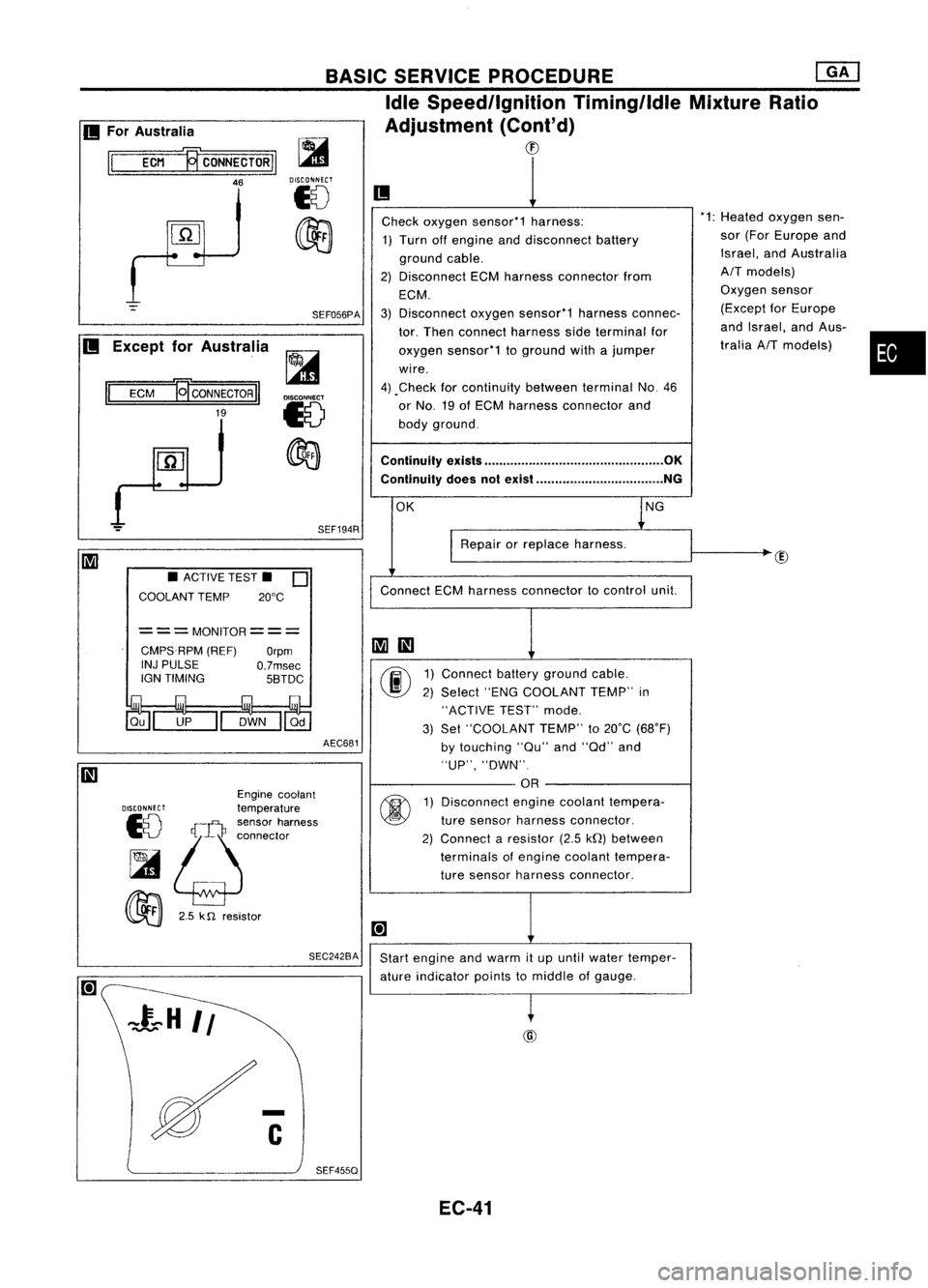
Check oxygen sensor*1 harness: *1:
Heated
1) Turn offengine anddisconnect battery sor
(For
ground cable. Israel,
a
2) Disconnect ECMharness connector from
AIT
mod
ECM. Oxygen
3) Disconnect oxygensensor*1 harnessconnec- (Except
tor. Then connect harness sideterminal for and
Isra
oxygen sensor*1 toground withajumper tralia
AI
wire.
4) .Check forcontinuity betweenterminalNo.46
or No. 19ofECM harness connector and
body ground.
Continuity exists................................................ OK
Continuity doesnotexist .................................. NG
OK lNG
I
Repair orreplace harness.
Connect ECMharness connector tocontrol unit.
~
III
00
1)
Connect batteryground cable.
2) Select "ENGCOOLANT TEMP"in
"ACTIVE TEST"mode.
3) Set "COOLANT TEMP"to20°C (68°F)
by touching "au"and"ad" and
"UP", "DWN".
OR
@
1)
Disconnect enginecoolant tempera-
ture sensor harness connector.
2) Connect aresistor (2.5kQ)between
terminals ofengine coolant tempera-
ture sensor harness connector.
[+]
Start engine andwarm itup until water temper-
ature indicator pointstomiddle ofgauge.
~
BASIC
SERVICE PROCEDURE ~
Idle Speed/Ignition Timing/IdleMixtureRatio
Adjustment (Cont'd)
CD
SEF194R
SEF056PA
~
DISCONNECT
18
~
AEC681
===MONITOR===
CMPS.RPM (REF)
Orpm
INJ PULSE
O.7msec
IGN TIMING 5BTDC
SEC242BA
•
ACTIVE TEST.
0
COOLANT TEMP 20°C
Engine coolant
DISCONNECT
temperature
10
!;j:~:~~'~";"'"
~
00
2.5k
n
resistor
II
ECM
19'
CONNECTOR
II
19
II
For Australia
II
ECM ~CONNECTORII
46
II
Except forAustralia
SEF455Q EC-41
Page 761 of 1701
@@
'1: Heated oxygen sensor(ForEurope
and Israel, andAustralia AITmod-
els) Oxygen sensor(Except forEurope
and Israel, andAustralia AITmod-
els)
Ii
1
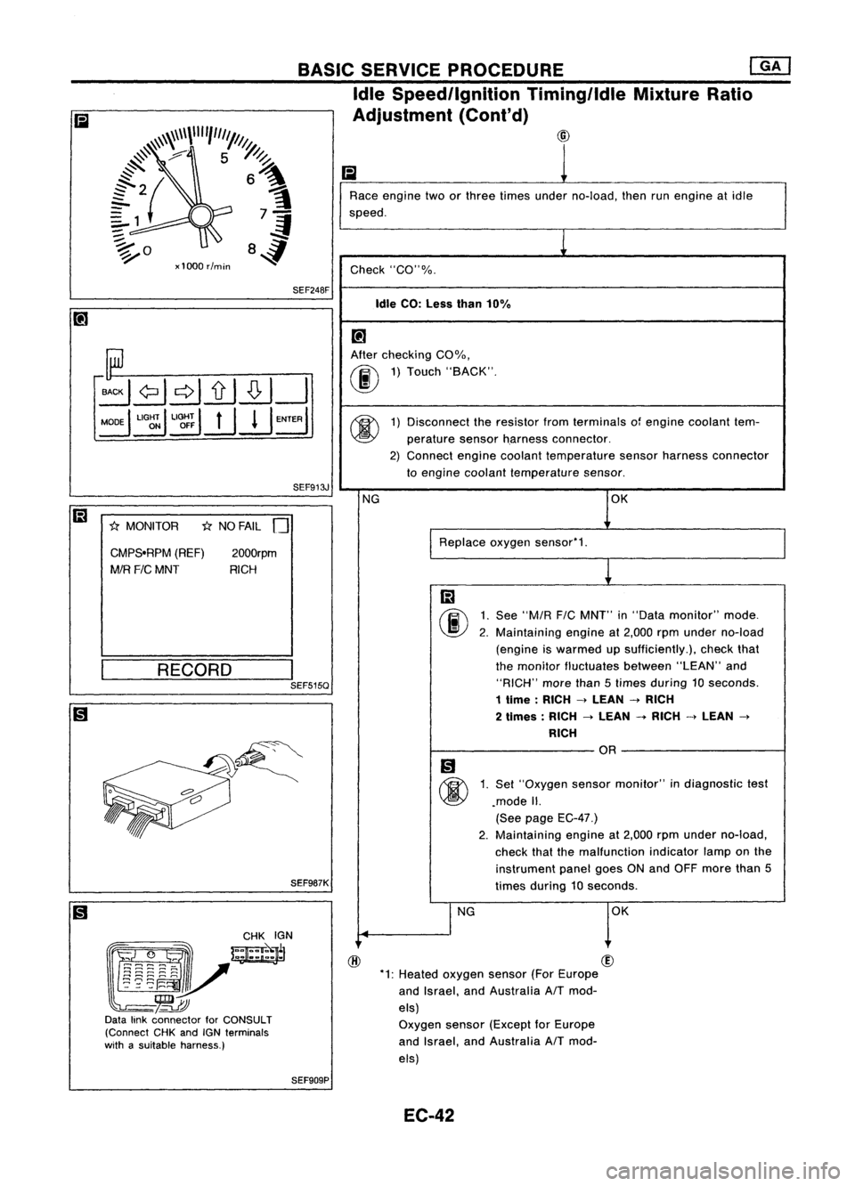
Race engine twoorthree times under no-load, thenrunengine atidle
speed.
1
Check "CO"%.
Idle CO:Less than10%
[!J
After checking COOJo,
00
1)
Touch "BACK".
@
1)
Disconnect theresistor fromterminals ofengine coolant tem-
perature sensorh.arness connector.
2) Connect enginecoolant temperature sensorharness connector
to engine coolant temperature sensor.
NG OK
Replace oxygensensor'1.
m
00
1.
See
"M/R
FIC
MNT" in"Data monitor" mode.
2. Maintaining engineat2,000 rpmunder no-load
(engine iswarmed upsufficiently.), checkthat
the monitor fluctuates between"LEAN"and
"RICH" morethan5times during 10seconds.
1 time :RICH
->
LEAN
->
RICH
2 times: RICH
->
LEAN
-+
RICH
->
LEAN
->
RICH
OR
Ii)
@
1.
Set "Oxygen sensormonitor" indiagnostic test
.mode II.
(See page EC-47.)
2. Maintaining
engineat2,000 rpmunder no-load,
check thatthemalfunction indicatorlamponthe
instrument panelgoesONand OFF more than5
times during 10seconds.
I
NG OK
SEF913J
2000rpm
RICH
1;:(
NO FAIL
0
SEF248F
CMPS.RPM (REF)
MIR
FIC
MNT
1;:(
MONITOR
BASIC
SERVICE PROCEDURE ~
Idle Speed/Ignition TiminglldleMixtureRatio
Adjustment (Cont'd)
~\\~\\\\""1"'1///1.
@
#'
7 5~
~ ~
{2{ 6~
?1 7-=1
:;::. .;f
~o 84
xl000 rlmin
SEF987K
(gJ~
~~~~N
l~~i~V-=~
-~
Data linkconnector forCONSULT
(Connect CHKandIGNterminals
with asuitable harness.)
__
R_E_C_O_R_D __
I
SEF515Q
SEF909P EC-42
Page 762 of 1701
![NISSAN ALMERA N15 1995 Service Manual BASICSERVICE PROCEDURE []KJ
Idle Speed/Ignition Timing/IdleMixtureRatio
Adjustment (Cont'd)
@
Connect oxygensensorharness connector tooxygen
sensor.
Check fuelpressure regulator.
(See page EC-33 NISSAN ALMERA N15 1995 Service Manual BASICSERVICE PROCEDURE []KJ
Idle Speed/Ignition Timing/IdleMixtureRatio
Adjustment (Cont'd)
@
Connect oxygensensorharness connector tooxygen
sensor.
Check fuelpressure regulator.
(See page EC-33](/manual-img/5/57349/w960_57349-761.png)
BASICSERVICE PROCEDURE []KJ
Idle Speed/Ignition Timing/IdleMixtureRatio
Adjustment (Cont'd)
@
Connect oxygensensorharness connector tooxygen
sensor.
Check fuelpressure regulator.
(See page EC-33.)
.
Check massairflow sensor anditscircuit.
(See page EC-107.)
Check injector anditscircuit.
(See page EC-141.)
Clean orreplace ifnecessary.
Check engine coolant temperature sensoranditscir-
cuit. (See page EC-112.)
Check ECMfunction* bysubstituting anotherknown
good ECM.
*.ECM maybethe caus
but this israrely thece
of aproblem,
ase.
•
EC-43
Page 765 of 1701
ON-BOARDDIAGNOSTIC SYSTEMDESCRIPTION @KJ
Malfunction Indicatorlamp(Mil)(Cont'd)
DIAGNOSTIC TESTMODE I-BULB CHECK
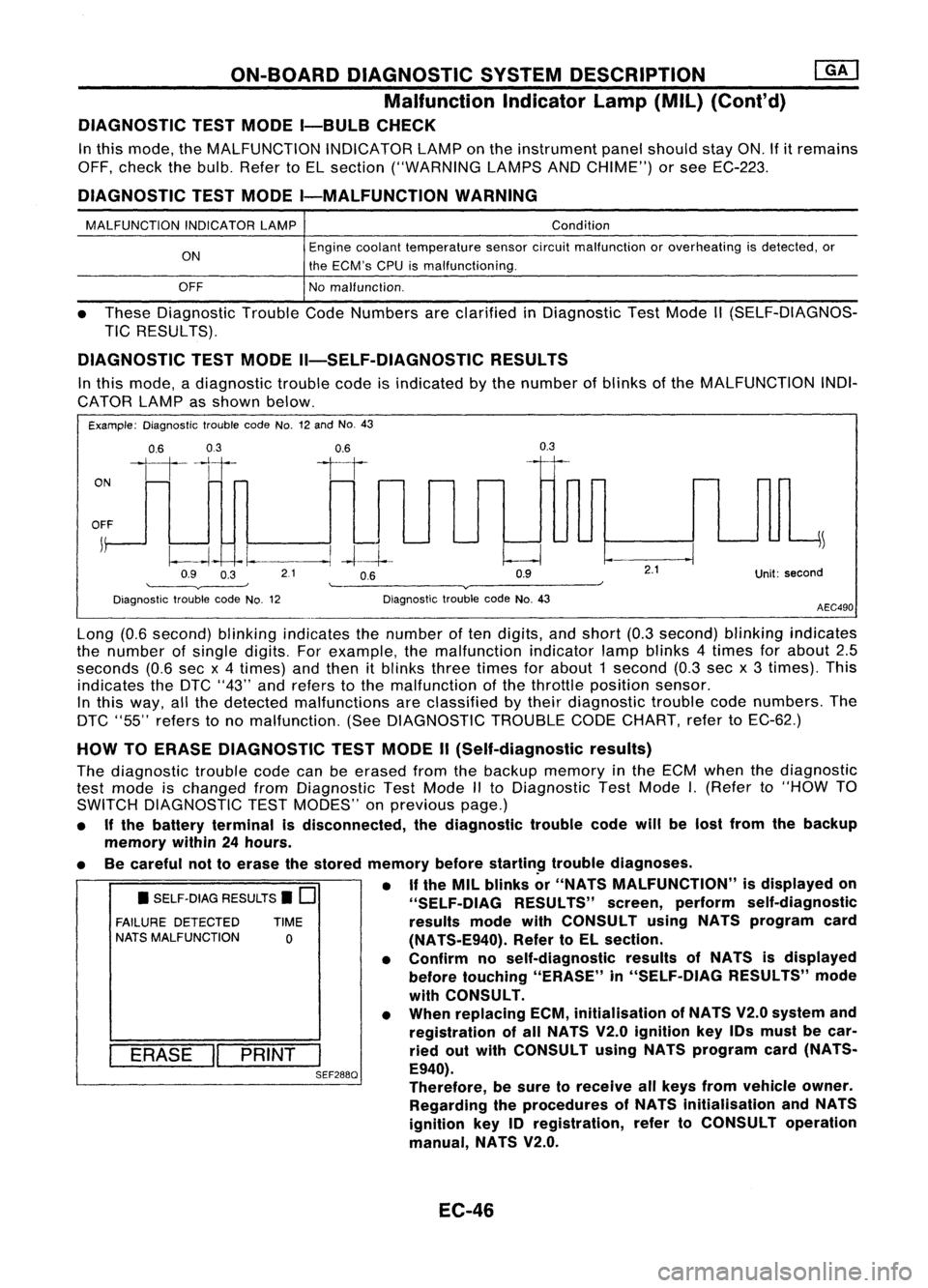
In this mode, theMALFUNCTION INDICATORLAMPonthe instrument panelshould stayON.Ifitremains
OFF, check thebulb. Refer toEL section ("WARNING LAMPSANDCHIME") orsee EC-223.
DIAGNOSTIC TESTMODE I-MALFUNCTION WARNING
MALFUNCTION INDICATORLAMP
ON
OFF Condition
Engine coolant temperature sensorcircuitmalfunction oroverheating isdetected, or
the ECM's CPUismalfunctioning.
No malfunction.
• These Diagnostic TroubleCodeNumbers areclarified inDiagnostic TestMode II(SELF-DIAGNOS-
TIC RESULTS).
DIAGNOSTIC TESTMODE II-SELF-DIAGNOSTIC RESULTS
In this mode, adiagnostic troublecodeisindicated bythe number ofblinks ofthe MALFUNCTION INDI-
CATOR LAMPasshown below.
Example: Diagnostic troublecodeNo.12and No.43
ON
0.6
03
111-'1
0.6
II
0.3
OFF
j
~
~~ -I.
--.1
-4--1--
Q9 O~ 21 OB Q9
'--------v----' '--------v------~
Diagnostic troublecodeNo.12 DiagnostictroublecodeNo.43
2.1
Unit:second
AEC490
• SELF-DIAG RESULTS.
0
FAILURE DETECTED TIME
NATS MALFUNCTION
0
I
ERASE
II
PRINT
I
SEF288Q
Long
(0.6second) blinkingindicates thenumber often digits, andshort (0.3second) blinkingindicates
the number ofsingle digits. Forexample, themalfunction indicatorlampblinks 4times forabout 2.5
seconds (0.6secx4 times) andthen itblinks threetimes forabout 1second (0.3secx3 times). This
indicates theDTC "43" andrefers tothe malfunction ofthe throttle position sensor.
In this way, allthe detected malfunctions areclassified bytheir diagnostic troublecodenumbers. The
DTC "55" refers tono malfunction. (SeeDIAGNOSTIC TROUBLECODECHART, refertoEC-62.)
HOW TOERASE DIAGNOSTIC TESTMODE II(Self-diagnostic results)
The diagnostic troublecodecanbeerased fromthebackup memory inthe ECM when thediagnostic
test mode ischanged fromDiagnostic TestMode IIto Diagnostic TestMode
I.
(Refer to"HOW TO
SWITCH DIAGNOSTIC TESTMODES" onprevious page.)
• Ifthe battery terminal isdisconnected, thediagnostic troublecodewillbelost from thebackup
memory within24hours.
• Becareful nottoerase thestored memory before
startin~
troublediagnoses.
• If
the MIL blinks or"NATS MALFUNCTION" isdisplayed on
"SELF-OIAG RESULTS"screen,perform self-diagnostic
results modewithCONSULT usingNATS program card
(NATS-E940). RefertoEL section.
• Confirm noself-diagnostic resultsofNATS isdisplayed
before touching "ERASE" in"SELF-DIAG RESULTS"mode
with CONSULT.
• When replacing ECM,initialisation ofNATS V2.0system and
registration ofall NATS V2.0ignition key10smust becar-
ried outwith CONSULT usingNATS program card(NATS-
E940).
Therefore, besure toreceive allkeys from vehicle owner.
Regarding theprocedures ofNATS initialisation andNATS
ignition key10registration, refertoCONSULT operation
manual, NATS V2.0.
EC-46
Page 766 of 1701
ON-BOARDDIAGNOSTIC SYSTEMDESCRIPTION
[QKJ
Malfunction Indicatorlamp(Mil)(Cont'd)
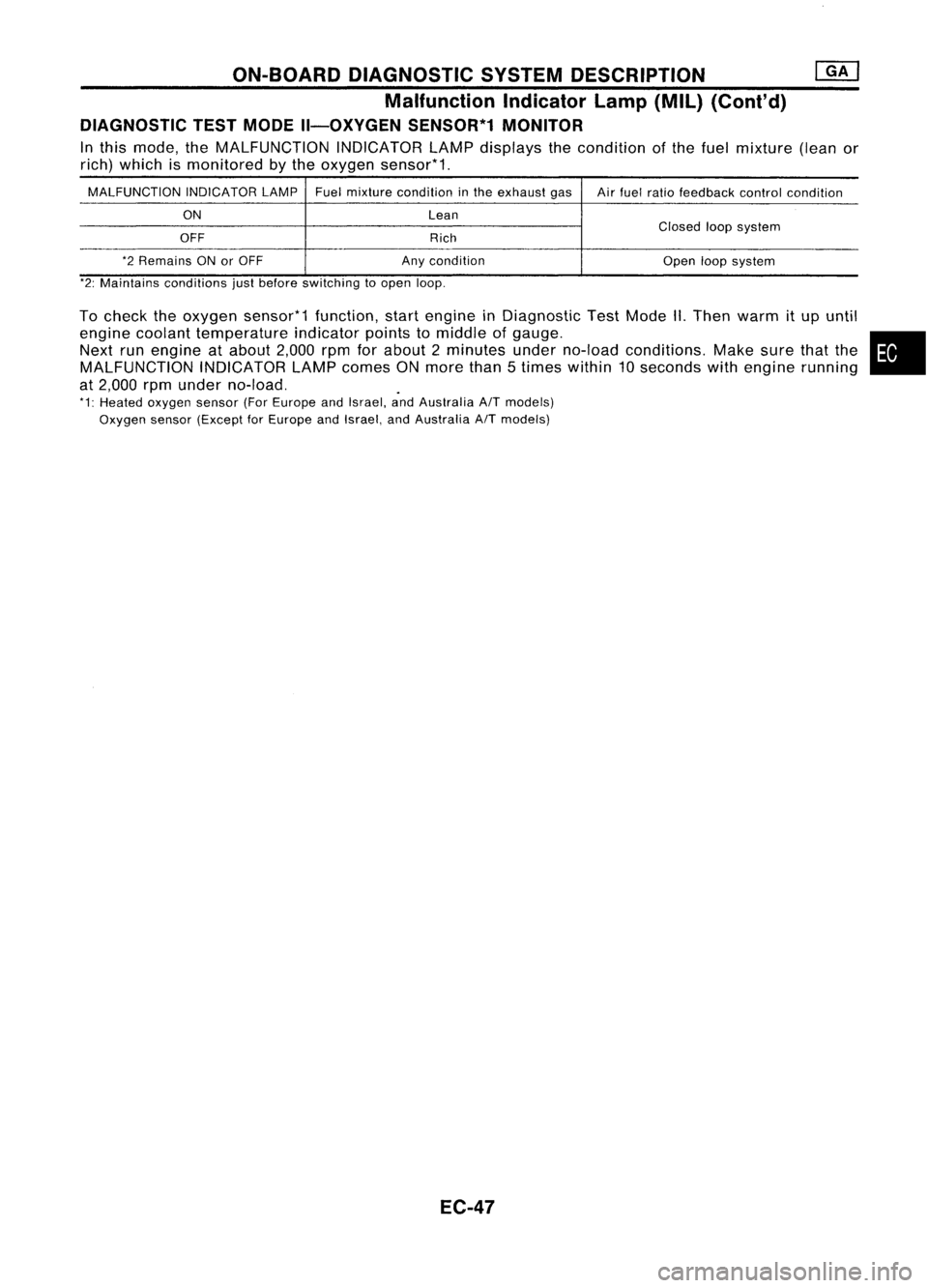
DIAGNOSTIC TESTMODE II-OXYGEN SENSOR*1MONITOR
In this mode, theMALFUNCTION INDICATORLAMPdisplays thecondition ofthe fuel mixture (leanor
rich) which ismonitored bythe oxygen sensor*1.
MALFUNCTION INDICATORLAMPFuelmixture condition inthe exhaust gas
Airfuel ratio feedback controlcondition
ON Lean
OFF RichClosed
loopsystem
*2 Remains ONorOFF Anycondition
Openloopsystem
*2: Maintains conditions justbefore switching toopen loop.
To check theoxygen sensor*1 function,startengine inDiagnostic TestMode II.Then warm itup until
engine coolant temperature indicatorpointstomiddle ofgauge. •
Next runengine atabout 2,000rpmforabout 2minutes underno-load conditions. Makesurethatthe
MALFUNCTION INDICATORLAMPcomes ONmore than5times within 10seconds withengine running
at 2,000 rpmunder no-load. .
*1: Heated oxygen sensor(ForEurope andIsrael, andAustralia
AfT
models)
Oxygen sensor(Except forEurope andIsrael, andAustralia
AfT
models)
EC-47
Page 768 of 1701
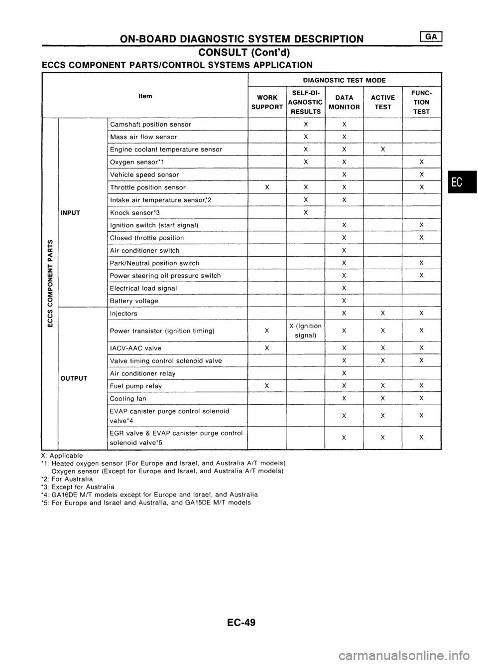
ON-BOARDDIAGNOSTIC SYSTEMDESCRIPTION
CONSULT (Cont'd)
ECCS COMPONENT PARTS/CONTROL SYSTEMSAPPLICATION
DIAGNOSTICTESTMODE
Item WORKSELF-DI-
ACTIVEFUNC-
DATA
SUPPORT AGNOSTIC
MONITOR TION
TEST
RESULTS TEST
Camshaft positionsensor
X
X
Mass airflow sensor
X
X
Engine coolant temperature sensor
X
X X
Oxygen sensor'1
X
X X
Vehicle speedsensor
XX
Throttle positionsensor
XX
X X
Intake airtemperature sensor.'2
X
X
INPUT
Knock
sensor'3
X
Ignition switch(startsignal)
XX
I/)
Closed
throttle position
X
X
l-
ll:
Airconditioner switch
X
<
~
Park/Neutralpositionswitch
X
X
I-
Z
UJ
Powersteering oilpressure switch
XX
z
0
Electricalloadsignal
X
~
:E
0
Batteryvoltage
X
u
I/)
Injectors
XX
X
u
u
UJ
X(Ignition
Power transistor (Ignitiontiming) X X
XX
signal)
IACV-AAC valve X
XX
X
Valve timing control solenoid valve XX
X
OUTPUT
Air
conditioner relay
X
Fuel pump relay XX
XX
Cooling fan XX
X
EVAP canister purgecontrol solenoid
XX X
valve'4
EGR valve
&
EVAP canister purgecontrol
XX
X
solenoid valve'5
X: Applicable
'1: Heated oxygen sensor(ForEurope andIsrael, andAustralia AITmodels)
Oxygen sensor(Except forEurope andIsrael, andAustralia AITmodels)
'2: For Australia
'3: Except forAustralia
'4: GA16DE
MIT
models exceptforEurope andIsrael, andAustralia
'5: For Europe andIsrael andAustralia, andGA15DE
MIT
models
EC-49
•