Page 954 of 1701

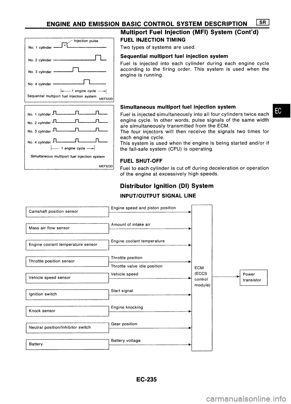
Twotypes ofsystems areused.
Sequential multiportfuelinjection system
Fuel isinjected intoeach cylinder duringeachengine cycle
according tothe firing order. Thissystem isused when the
engine isrunning.
ENGINE
ANDEMISSION BASICCONTROL SYSTEMDESCRIPTION ~
Multiport FuelInjection (MFI)System (Cont'd)
FUEL INJECTION TIMING
..--./ Injection pulse
NO.1 cylinder
---1
0/1 _
NO.3 cylinder
~n~ _
No.2
cylinder
rL
NO.4 cylinder
~n~_
~ 1engine cycle
----j
Sequential multiportfuelinjection system
MEF522D
No. 1cylinder
jl
n
rL-
No. 2cylinder
jl
n
rL-
No. 3cylinder
]l
n
rL-
NO.4 cylinder
D
n
fL-.
~- 1engine cycle
---1
Simultaneous multiportfuelinjection system
MEF523D Simultaneous
multipartfuelinjection system
Fuel isinjected simultaneously intoallfour cylinders twiceeach
engine cycle.Inother words, pulsesignals ofthe same width
are simultaneously transmittedfromtheECM.
The four injectors willthen receive thesignals twotimes for
each engine cycle.
This system isused when theengine isbeing started and/orif
the fail-safe system(CPU)isoperating.
FUEL SHUT-OFF
Fuel toeach cylinder iscut offduring deceleration oroperation
of the engine atexcessively highspeeds.
•
Distributor Ignition(DI)System
INPUT/OUTPUT SIGNALLINE
Camshaft positionsensor Engine
speedandpiston position
Mass airflow sensor Amount
ofintake air
Engine coolant temperature sensor Engine
coolant temperature
Throttle position sensor
I
Vehicle speedsensor Throttle
position
Throttle valveidleposition
I
Vehicle speed ECM
(ECCS
control module) Power
transistor
Ignition switch Start
signal
Knock sensor Engine
knocking
Neutral position/Inhibitor switchGear
position
Battery Battery
voltage
EC-235
Page 955 of 1701

A
N
600 1,000 1,4001,8002,200
Engine speed(rpm) SEF742M
Tp
(msec)
1.75
~ 1.50
.~
3l
1.25
:;
a.
c:
1.00
.Q
~ 0.75
E ENGINE
ANDEMISSION BASICCONTROL SYSTEMDESCRIPTION
Distributor Ignition(01)System (Cont'd)
SYSTEM DESCRIPTION
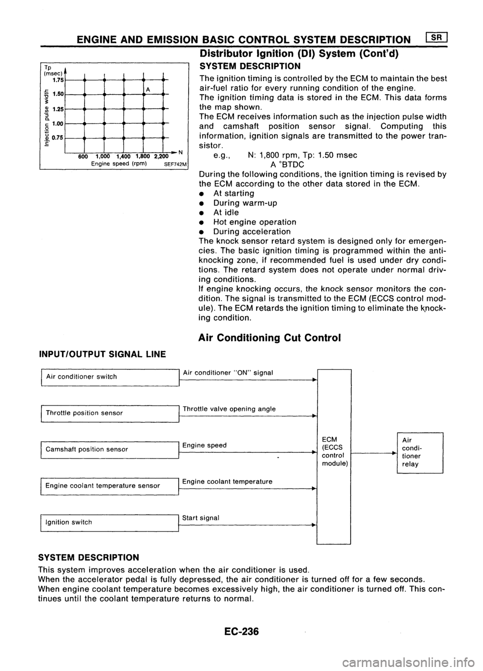
The ignition timingiscontrolled bythe ECM tomaintain thebest
air-fuel ratioforevery running condition ofthe engine.
The ignition timingdataisstored inthe ECM. Thisdataforms
the map shown.
The ECM receives information suchasthe injection pulsewidth
and camshaft positionsensorsignal.Computing this
information, ignitionsignalsaretransmitted tothe power tran-
sistor.
e.g., N:1,800 rpm,Tp:1.50 msec
AOBTDC
During thefollowing conditions, theignition timingisrevised by
the ECM according tothe other datastored inthe ECM.
• Atstarting
• During warm-up
• Atidle
• Hot engine operation
• During acceleration
The knock sensor retardsystem isdesigned onlyforemergen-
cies. Thebasic ignition timingisprogrammed withintheanti-
knocking zone,ifrecommended fuelisused under drycondi-
tions. Theretard system doesnotoperate undernormal driv-
ing conditions.
If engine knocking occurs,theknock sensor monitors thecon-
dition. Thesignal istransmitted tothe ECM (ECCS control mod-
ule). TheECM retards theignition timingtoeliminate thek.nock-
ing condition.
Air Conditioning CutControl
INPUT/OUTPUT SIGNALLINE
Air conditioner switch
Throttle position sensor
Camshaft positionsensor
Engine coolant temperature sensor
Ignition switch Air
conditioner "ON"signal
Throttle valveopening angle
Engine speed
Engine coolant temperature
Start signal
ECM
(ECCS
control module)
Air
condi-
tioner
relay
SYSTEM DESCRIPTION
This system improves acceleration whentheairconditioner isused.
When theaccelerator pedalisfully depressed, theairconditioner isturned offfor afew seconds.
When engine coolant temperature becomesexcessively high,theairconditioner isturned off.This con-
tinues untilthecoolant temperature returnstonormal.
EC-236
Page 956 of 1701
ENGINEANDEMISSION BASICCONTROL SYSTEMDESCRIPTION
Fuel CutControl (atnoload
&
high engine
speed)
INPUT/OUTPUT SIGNALLINE
Vehicle speedsensor Vehicle
speed
Neutral position/lnhibitor switch
Throllle positionsensor
Engine coolant temperature sensor
Camshaft positionsensor Neutral
position
Throllle position
Engine coolant temperature
.
Engine speed
ECM
(ECCS
control module) Injectors
•
If the engine speedisabove 3,950rpmwith noload (for
example, inneutral andengine speedover3,950 rpm)fuelwill
be cut offafter some time.Theexact timewhen thefuel iscut
off varies basedonengine speed.
Fuel cutwill operate untiltheengine speedreaches 1,150rpm,
then fuelcutiscancelled.
NOTE:
This function isdifferent thandeceleration controllistedunder
"Multipart FuelInjection (MFI)System" onEC-233.
EC-237
Page 962 of 1701

BASICSERVICE PROCEDURE
Idle Speedllgnition TiminglldleMixtureRatio
Adjustment
PREPARATION
• Make surethatthefollowing partsarein
good order.
(1) Battery
(2) Ignition system
(3) Engine oiland coolant levels
(4) Fuses
(5) ECM harness connector
(6) Vacuum hoses
(7) Airintake system
(Oil filler cap,oillevel gauge, etc.)
(8) Fuel pressure
(9) Engine compression
(10) Throttle valve
Overall inspection sequence
INSPECTION
•
•
•
•
•
•
On
models equipped withairconditioner,
checks shouldbecarried outwhile theair
conditioner is"OFF".
On models equipped withautomatic
transaxle, whenchecking idlespeed, ignition
timing andmixture ratio,checks shouldbe
carried outwhile shiftlever isin "N" position.
When measuring "CO"percentage, insert
probe morethan40cm (15.7 in)into tailpipe.
Turn offheadlamps, heaterblower, rear
defogger. Keep frontwheels pointed straight ahead.
Make thecheck afterthecooling fanhas
stopped.
•
Perform diagnostic testmode II
(Self-diagnostic results).
OK
Check
&
adjust ignition timing.
Check
&
adjust idlespeed.
Check heated oxygen sensor
function. NG
Repair orreplace.
NG Check heated oxygen sensor
harness. NG
Repair orreplace harness.
OK OK
Check CO%. OKReplace heatedoxygen sensor.
NG
INSPECTION END Check
emission controlparts
and repair orreplace ifneces-
sary.
EC-243
NG
Check heated oxygen sensor
function.
OK
Page 963 of 1701

@
START
Visually checkthefollowing:
• Air cleaner clogging
• Hoses andduct forleaks
• Electrical connectors
• Gasket (intakemanifold, cylinderhead,exhaust system)
• Throttle valveandthrottle position sensoroperation
m
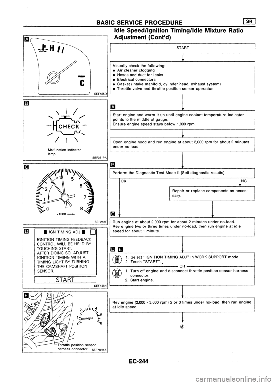
Start engine andwarm itup until engine coolant temperature indicator
points tothe middle ofgauge.
Ensure enginespeedstaysbelow 1,000rpm.
1
Open engine hoodandrunengine atabout 2,000rpmforabout 2minutes
under no-load.
Ii]
Perform theDiagnostic TestMode
1\
(Self-diagnostic results).
OK ~NG
Repair orreplace components asneces-
sary.
[!J
Run engine atabout 2,000rpmforabout 2minutes underno-load.
Rev engine twoorthree times under no-load, thenrunengine atidle
speed forabout 1minute .
li]1!I
00
1.
Select "IGNITION TIMINGADJ"inWORK SUPPORT mode.
2. Touch "START" .
.
OR
00
1.
Turn offengine anddisconnect throttleposition sensorharness
connector.
2. Start engine.
Rev engine (2,000-3,000 rpm)2or 3times under no-load, thenrunengine
at idle speed.
t
Throttle position sensor
harness connector SEF785KASEF051PA
BASIC
SERVICE PROCEDURE Em
Idle Speedllgnition TiminglldleMixtureRatio
Adjustment (Cont'd)
SEF248F
SEF455Q
Malfunction indicator
lamp \
I/
'~,,/
- CHECK-
,,/
........
/ I\
Ii] •IGN TIMING ADJ.
D
IGNITION TIMINGFEEDBACK
CONTROL WILLBEHELD BY
TOUCHING START.
AFTER DOING SO,ADJUST
IGNITION TIMINGWITHA
TIMING LIGHTBYTURNING
THE CAMSHAFT POSITION
SENSOR.
I
START
I
SEF546N
EC-244
Page 966 of 1701
![NISSAN ALMERA N15 1995 Service Manual Heatedoxygen sensor
harness connector BASIC
SERVICE PROCEDURE [][]
Idle Speed/Ignition Timing/IdleMixtureRatio
Adjustment (Cont'd)
@
II
MEF031DB
~io
ECM TIcoNNECTORl1
19
LEn
MEC712B
Check
NISSAN ALMERA N15 1995 Service Manual Heatedoxygen sensor
harness connector BASIC
SERVICE PROCEDURE [][]
Idle Speed/Ignition Timing/IdleMixtureRatio
Adjustment (Cont'd)
@
II
MEF031DB
~io
ECM TIcoNNECTORl1
19
LEn
MEC712B
Check](/manual-img/5/57349/w960_57349-965.png)
Heatedoxygen sensor
harness connector BASIC
SERVICE PROCEDURE [][]
Idle Speed/Ignition Timing/IdleMixtureRatio
Adjustment (Cont'd)
@
II
MEF031DB
~io
ECM TIcoNNECTORl1
19
LEn
MEC712B
Check
heated oxygen sensorharness:
1. Turn offengine anddisconnect batteryground
cable.
2. Disconnect ECMharness connector fromECM.
3. Disconnect heatedoxygen sensorharness con-
nector. Thenconnect harness sideterminal for
heated oxygen sensortoground withajumper
wire.
4. Check forcontinuity betweenterminal
@
ofECM
harness connector andbody ground.
Continuity exists OK
Continuity doesnotexist NG
OK
Repairorreplace harness.
Connect ECMharness connector toECM .
•
OR
1.
Connect batteryground cable.
2. Select "ENGCOOLANT TEMP"in
"ACTIVE TEST"mode.
3. Set "COOLANT TEMP"to20"C (68"F) by
touching "Qu"and"Qd" and"UP",
"DWN".
Disconnect enginecoolant temperature
sensor harness connector.
2. Connect aresistor (2.5kQ)between termi-
nals ofengine coolant temperature sensor
harness connector.
3. Connect batteryground cable.
Ii
AEC681
•
ACTIVE TEST.
0
COOLANT TEMP 20°C
===MONITOR=== CMPS.RPM (REF)
Orpm
INJ PULSE
O.7msec
IGN TIMING 5BTDC
DISCONNFCT
Enginecoolant
10 temperature
sensor
harness connector
~ ~
00
2.5
k0 resistor
Start
engine andwarm itup until engine coolant
temperature indicatorpointstomiddle ofgauge.
(Be sure tostart engine aftersetting "COOLANT
'-- A_E_C6_8-l2
TEMP"orinstalling a2.5 kQresistor.)
Ii
SEF455QEC-247
Page 967 of 1701

m
1
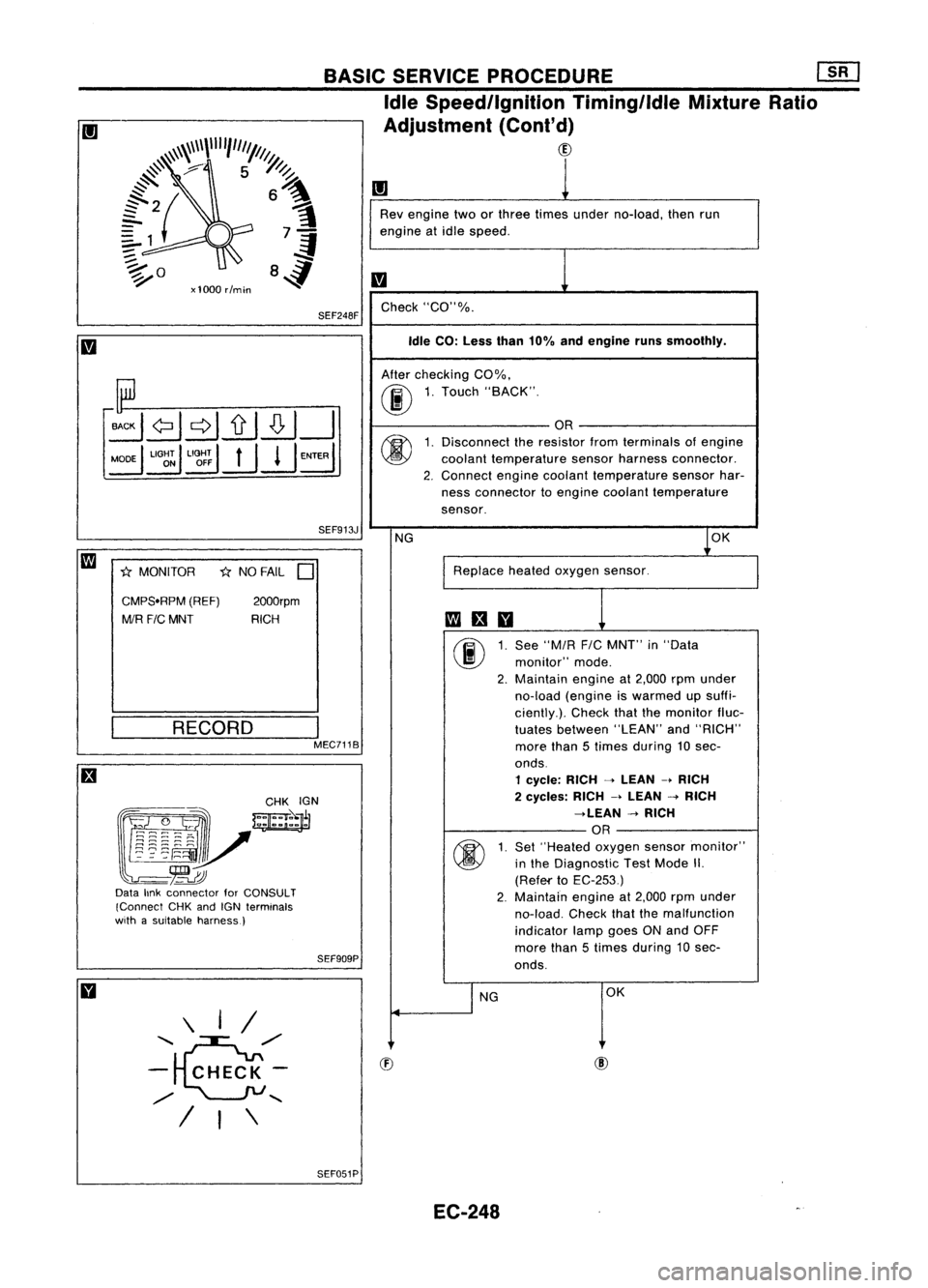
Rev engine twoorthree times under no-load, thenrun
engine atidle speed.
m
Check "CO"%.
Idle CO: Less than10%andengine runssmoothly.
After checking CO%.
00
1.
Touch "BACK".
OR
(j)
1.
Disconnect theresistor fromterminals ofengine
coolant temperature sensorharness connector.
2. Connect
enginecoolant temperature sensorhar-
ness connector toengine coolant temperature
sensor.
NG
1
0K
Replace heatedoxygen sensor.
fa
an
00
1.
See
"MIR
FIC
MNT" in"Data
monitor" mode.
2. Maintain
engineat2,000 rpmunder
no-load (engine iswarmed upsuffi-
ciently.). Checkthatthemonitor fluc-
tuates between "LEAN"and"RICH"
more than5times during 10sec-
onds.
1 cycle: RICH-->LEAN -.RICH
2 cycles: RICH-->LEAN -->RICH
-->LEAN -->RICH
OR
(j)
1.
Set
"Heated oxygensensormonitor"
in the Diagnostic TestMode II.
(Refef'to EC-253)
2. Maintain
engineat2,000 rpmunder
no-load. Checkthatthemalfunction
indicator lampgoesONand OFF
more than5times during 10sec-
onds.
I
NG OK
SEF913J
I
MEC7118
2000rpm
RICH
*
NO FAIL
D
RECORD
SEF909PBASIC
SERVICE PROCEDURE
mJ
Idle Speed/Ignition Timing/ldleMixtureRatio
Adjustment (Cont'd)
CID
SEF248F
\ I/
.........
~/'
- CHECK-
/
.......
/ I\
CMPS.RPM
(REF)
MIR F/CMNT
*
MONITOR
~~~~:?_-~ .
w=jr
~~~~"v
-~
Data linkconnector forCONSULT
(Connect CHKandIGN terminals
with asuitable harness)
SEF051PEC-248
Page 968 of 1701
,$
BASIC
SERVICE PROCEDURE
[]K]
Idle Speedllgnition TiminglldleMixtureRatio
Adjustment (Cont'd)
CD
•
ause ofaproblem, but
It
IS IS
rarely thecase.
1
Connect heatedoxygen sensorharness connec-
tor toheated oxygen sensor.
Check fuelpressure regulator.
(Refer toEC-242.)
Check massairflow sensor anditscircuit.
Refer toTROUBLE DIAGNOSIS FORDTC12.
(Refer toEC-293.)
Check injector anditscircuit.
Refer toTROUBLE DIAGNOSIS FORNON
DETECTABLE ITEMS.
(Refer toEC-324.)
Clean orreplace ifnecessary.
Check engine coolant temperature sensorand
its circuit. RefertoTROUBLE DIAGNOSIS FOR
DTC 13.
(Refer toEC-297.)
Check ECMfunction' bysubstituting another
known goodECM
•.ECM maybethe c
1
EC-249