Page 1296 of 1771
GAUGE ASSEMBLY
UNDER-HOOD FUSE/RELAY BOX
ABS INDICATOR LIGHT
BATTERY
(100 A) FUSE
IG (50 A) FUSE
STOP/ HORN
(20 A) FUSE
UNDER-DASH FUSE/RELAY BOX
UNDER-HOOD ABS FUSE/RELAY BOX
HEATER
CONTROL RELAY
(7.5 A) FUSE
BACK-UP LIGHTS/
METER LIGHTS
(SUN ROOF)
(10 A) FUSE
ECU (ECM)/
CRUISE CONTROL/
EAT ECU
(15 A) FUSE
ABS MOTOR (40 A) FUSE
ABS B1 (20 A) FUSE
ABS B2 (15 A) FUSE
ABS PUMP MOTOR RELAY
UNDER-DASH RELAY BOX
ABS UNIT (10 A) FUSE
REAR FAIL-SAFE RELAY
FRONT FAIL-SAFE RELAYProCarManuals.com
Page 1302 of 1771
DTC Indication Pattern (When the ABS control unit detected a problem three times.):
Turn the ignition switch ON (II). The ABS indicator light comes on for two seconds to check the bulb.
The ABS control unit indicates the DTC three times.
If you miscount the blinking frequency or if you recheck the blinking frequency, turn the ignition switch OFF then
turn it ON (II) to cycle the ABS indicator light again.
4. Remove the SCS service connector.
NOTE: The Malfunction Indicator Lamp (MIL) will stay on after the engine is started if the SCS service connector is
connected.
5. Remove the ABS B2 (15 A) fuse in the under-hood ABS fuse/relay box for at least three seconds to erase the ABS con-
trol unit's memory.ProCarManuals.com
Page 1321 of 1771
Component Locations
RIGHT-REAR WHEEL SENSOR
SERVICE CHECK CONNECTOR (2P)
ABS CONTROL UNIT
RIGHT-REAR WHEEL
SENSOR CONNECTOR
UNDER-DASH RELAY BOX
RIGHT-FRONT WHEEL
SENSOR CONNECTOR
UNDER-HOOD
FUSE/RELAY BOX
LEFT-REAR
WHEEL SENSOR
MODULATOR UNIT
UNDER-HOOD ABS
FUSE/RELAY BOX
LEFT-REAR WHEEL
SENSOR CONNECTOR
PARKING BRAKE SWITCH
UNDER-DASH FUSE/RELAY BOX
RIGHT-FRONT
WHEEL SENSOR
LEFT-FRONT WHEEL SENSOR
LEFT-FRONT WHEEL
SENSOR CONNECTORProCarManuals.com
Page 1322 of 1771
ABS INDICATOR LIGHT
BATTERY
(100 A) FUSE
STOP/ HORN
(20 A) FUSE
IG (50 A) FUSE
UNDER-DASH FUSE/RELAY BOX
UNDER-HOOD ABS FUSE/RELAY BOX
HEATER
CONTROL RELAY
(7.5 A) FUSE
BACK-UP LIGHTS/
METER LIGHTS
(SUN ROOF)
(10 A) FUSE
ECU (ECM)/
CRUISE CONTROL/
EAT ECU
(15 A) FUSE
ABS MOTOR (30 A) FUSE
ABS B1 (20 A) FUSE
UNDER-DASH RELAY BOX
ABS PUMP MOTOR RELAY
ABS UNIT (7.5 A) FUSE
FAIL-SAFE RELAYProCarManuals.com
Page 1497 of 1771

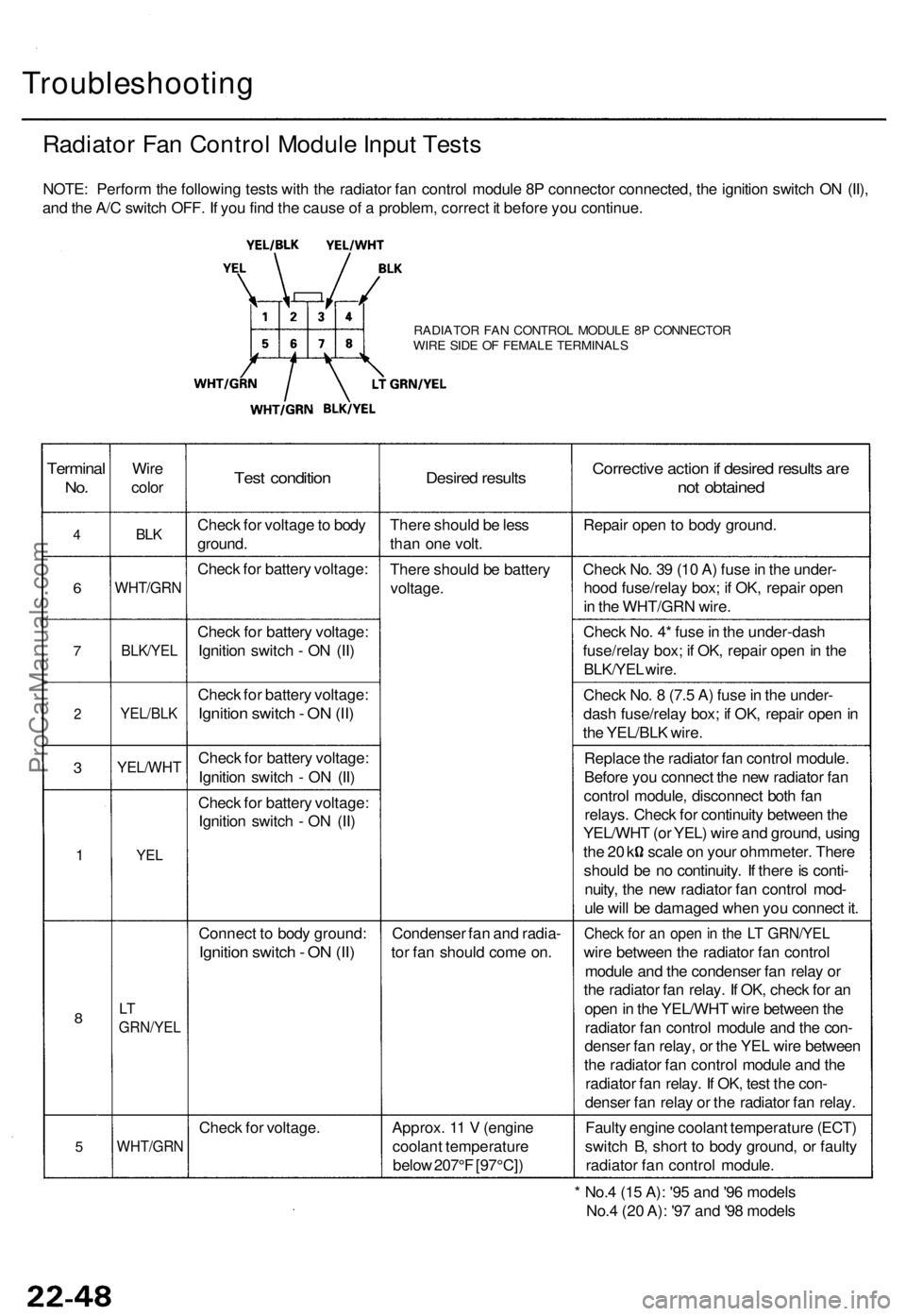
Troubleshooting
Radiator Fan Control Module Input Tests
NOTE: Perform the following tests with the radiator fan control module 8P connector connected, the ignition switch ON (II),
and the A/C switch OFF. If you find the cause of a problem, correct it before you continue.
RADIATOR FAN CONTROL MODULE 8P CONNECTOR
WIRE SIDE OF FEMALE TERMINALS
Terminal
No.
4
6
7
2
3
1
8
5
Wire
color
BLK
WHT/GRN
BLK/YEL
YEL/BLK
YEL/WHT
YEL
LT
GRN/YEL
WHT/GRN
Test condition
Check for voltage to body
ground.
Check for battery voltage:
Check for battery voltage:
Ignition switch - ON (II)
Check for battery voltage:
Ignition switch - ON (II)
Check for battery voltage:
Ignition switch - ON (II)
Check for battery voltage:
Ignition switch - ON (II)
Connect to body ground:
Ignition switch - ON (II)
Check for voltage.
Desired results
There should be less
than one volt.
There should be battery
voltage.
Condenser fan and radia-
tor fan should come on.
Approx. 11 V (engine
coolant temperature
below 207°F [97°C])
Corrective action if desired results are
not obtained
Repair open to body ground.
Check No. 39 (10 A) fuse in the under-
hood fuse/relay box; if OK, repair open
in the WHT/GRN wire.
Check No. 4* fuse in the under-dash
fuse/relay box; if OK, repair open in the
BLK/YEL wire.
Check No. 8 (7.5 A) fuse in the under-
dash fuse/relay box; if OK, repair open in
the YEL/BLK wire.
Replace the radiator fan control module.
Before you connect the new radiator fan
control module, disconnect both fan
relays. Check for continuity between the
YEL/WHT (or YEL) wire and ground, using
the 20 k scale on your ohmmeter. There
should be no continuity. If there is conti-
nuity, the new radiator fan control mod-
ule will be damaged when you connect it.
Check for an open in the LT GRN/YEL
wire between the radiator fan control
module and the condenser fan relay or
the radiator fan relay. If OK, check for an
open in the YEL/WHT wire between the
radiator fan control module and the con-
denser fan relay, or the YEL wire between
the radiator fan control module and the
radiator fan relay. If OK, test the con-
denser fan relay or the radiator fan relay.
Faulty engine coolant temperature (ECT)
switch B, short to body ground, or faulty
radiator fan control module.
* No.4 (15 A): '95 and '96 models
No.4 (20 A): '97 and '98 modelsProCarManuals.com
Page 1536 of 1771

Troubleshooting
Tips and Precautions
Before Troubleshooting
Check applicable fuses in the appropriate fuse/relay
box.
Check the battery for damage, state of charge, and
clean and tight connections.
Check the alternator belt tension.
CAUTION:
Do not quick-charge a battery unless the battery
ground cable has been disconnected, otherwise you
will damage the alternator diodes.
Do not attempt to crank the engine with the battery
ground cable loosely connected or you will severely
damage the wiring.
Handling Connectors
Make sure the connectors are clean and have no loose
wire terminals.
Make sure multiple cavity connectors are packed with
grease (except waterproof connectors).
All connectors have push-down release type locks.
LOCKING TAB
Some connectors have a clip on their side used to
attach them to a mount bracket on the body or on
another component. This clip has a pull type lock.
Some mounted connectors cannot be disconnected
unless you first release the lock and remove the con-
nector from its mount bracket.
LOCKING
PAWL ON
OTHER
HALF OF
CONNECTOR
Pull to
disengage
BRACKET
Never try to disconnect connectors by pulling on
their wires; pull on the connector halves instead.
Always reinstall plastic covers.
Before connecting connectors, make sure the termi-
nals are in place and not bent.
BENT TERMINAL
Check for loose retainer and rubber seals.
RETAINER
RUBBER SEAL RETAINER
The backs of some connectors are packed with
grease. Add grease if necessary. If the grease is con-
taminated, replace it.
LOCKING TABProCarManuals.com
Page 1539 of 1771
Relay and Control Unit Locations
Engine Compartment
UNDER-HOOD ABS
FUSE/RELAY BOX
ABS PUMP MOTOR RELAY
HEADLIGHT
RELAY
DIMMER RELAY
TAILLIGHT
RELAY
POWER WINDOW
RELAY
UNDER-HOOD
FUSE/RELAY BOXProCarManuals.com
Page 1549 of 1771

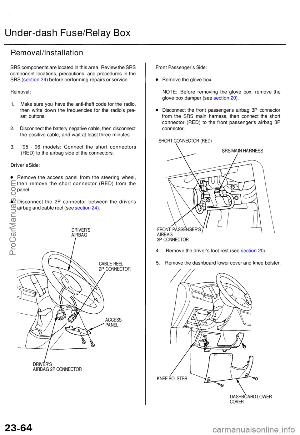
Under-dash Fuse/Rela y Bo x
Removal/Installatio n
SRS component s ar e locate d in thi s area . Revie w th e SR S
componen t locations , precautions , an d procedure s i n th e
SR S (sectio n 24 ) befor e performin g repair s o r service .
Removal :
1. Mak e sur e yo u hav e th e anti-thef t cod e fo r th e radio ,
the n writ e dow n th e frequencie s fo r th e radio' s pre -
se t buttons .
2 . Disconnec t th e batter y negativ e cable , the n disconnec t
th e positiv e cable , an d wai t a t leas t thre e minutes .
3 . '9 5 - 9 6 models : Connec t th e shor t connector s
(RED ) t o th e airba g sid e o f th e connectors .
Driver' s Side :
Remov e th e acces s pane l fro m th e steerin g wheel ,
the n remov e th e shor t connecto r (RED ) fro m th e
panel .
Disconnec t th e 2 P connecto r betwee n th e driver' s
airba g an d cabl e ree l (se e sectio n 24 ).
DRIVER' SAIRBAG
CABLE REE L2P CONNECTO R
ACCESSPANEL
DRIVER' SAIRBAG 2 P CONNECTO R
Front Passenger' s Side :
Remov e th e glov e box .
NOTE : Befor e removin g th e glov e box , remov e th e
glov e bo x dampe r (se e sectio n 20 ).
Disconnec t th e fron t passenger' s airba g 3 P connecto r
fro m th e SR S mai n harness , the n connec t th e shor t
connecto r (RED ) t o th e fron t passenger' s airba g 3 P
connector .
SHORT CONNECTO R (RED )
SRS MAI N HARNES S
FRONT PASSENGER' SAIRBAG3P CONNECTO R
4. Remov e th e driver' s foo t res t (se e sectio n 20 ).
5 . Remov e th e dashboar d lowe r cove r an d kne e bolster .
KNEE BOLSTE R
DASHBOARD LOWE R
COVER
ProCarManuals.com