Page 647 of 1771
Precautions/Procedures
Wiring Precaution s
• Neve r attemp t t o modify , splic e o r repai r SR S wiring .
NOTE : SR S wirin g ca n b e identifie d b y specia l yello w
oute r covering .
• B e sur e to instal l th e harnes s wire s s o tha t the y ar e no t
pinche d o r interferin g wit h othe r parts .
Mak e sur e al l SR S groun d location s ar e clea n an d
ground s ar e securel y fastene d fo r optimu m metal-to -
meta l contact . Poo r groundin g ca n caus e intermitten t
problems tha t ar e difficul t t o diagnose .
Disconnectin g th e SR S Connecto r a t th e Under-das h
Fuse/Relay Box :
CAUTION : Avoi d breakin g th e connector ; it' s double -
locked.
1. Firs t lif t th e connecto r li d wit h a thi n screwdriver , the n
pres s th e connecto r ta b down , an d pul l th e connecto r
out.
UNDER-DAS H FUSE/RELA Y BO X
SRSMAI NHARNES S
TAB
2. T o reinstal l th e connector , pus h it int o positio n unti l i t
clicks , the n clos e it s lid .
ProCarManuals.com
Page 720 of 1771
Engine Removal/Installation
Removal (cont'd)
7. Remove the battery cables from the under-hood fuse/
relay box.
BATTERY
CABLES
8.
9.
UNDER-HOOD
FUSE/RELAY BOX
Disconnect the engine wire harness connector on
the right (passenger's) side of the engine compart-
ment.
Remove the battery cable from the under-hood ABS
fuse/relay box.
BATTERY
CABLE
ENGINE WIRE
HARNESS
UNDER-HOOD ABS
FUSE/RELAY BOX
10. Remove the intake air duct and vacuum hose.
INTAKE AIR
DUCT
11.
VACUUM
HOSE
Remove the adjusting bolt, locknut and mounting
bolt, then remove the power steering (P/S) pump
belt and pump.
MOUNTING BOLT
10 x
1.25
mm
49 N-m (5.0 kgf-m, 36 Ibf-ft)
ADJUSTING
BOLT
P/S PUMP
BELT
LOCKNUT
8 x
1.25
mm
22 N-m (2.2 kgf-m,
16 Ibf-ft)ProCarManuals.com
Page 862 of 1771
II. Engine Control Module (ECM) Reset Procedure
Either of the following actions will reset the ECM.
• Use the OBD II scan tool or Honda PGM Tester to clear the ECM's memory.
NOTE: See the OBD II scan tool or Honda PGM Tester user's manuals for specific operating instructions.
• Turn the ignition switch OFF. Remove the BACK UP RADIO (10 A) fuse from the under-hood fuse/relay box for
10 seconds.
BACK UP RADIO
(10 A) FUSE
UNDER-HOOD
FUSE/RELAY
BOX
III. Final Procedure (this procedure must be done after any troubleshooting)
1. Remove the SCS Service Connector if it is connected.
NOTE: If the SCS service connector is connected and there are no DTCs stored in the ECM, the MIL will stay
on when the ignition switch is turned ON (II).
2. Do the ECM Reset Procedure.
3. Turn the ignition switch OFF.
4. Disconnect the OBD II scan tool or Honda PGM Tester from the Data Link Connector (16P).ProCarManuals.com
Page 879 of 1771

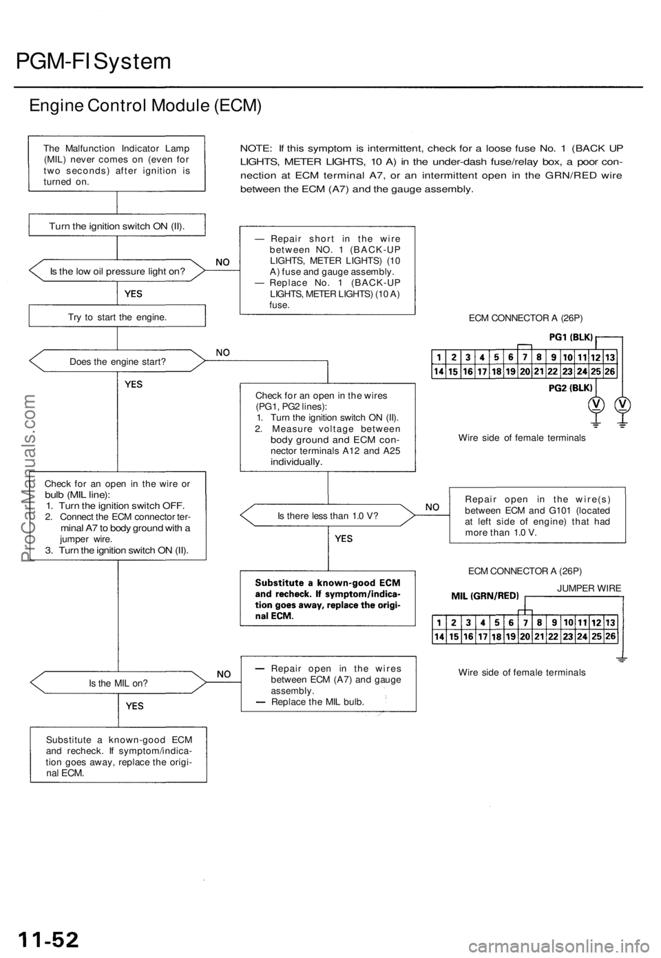
PGM-FI System
Engine Control Module (ECM)
Is the low oil pressure light on?
Try to start the engine.
Does the engine start?
Check for an open in the wire or
bulb (MIL line):
1. Turn the ignition switch OFF.
2. Connect the ECM connector ter-
minal A7 to body ground with a
jumper wire.
3. Turn the ignition switch ON (II).
NOTE: If this symptom is intermittent, check for a loose fuse No. 1 (BACK UP
LIGHTS, METER LIGHTS, 10 A) in the under-dash fuse/relay box, a poor con-
nection at ECM terminal A7, or an intermittent open in the GRN/RED wire
between the ECM (A7) and the gauge assembly.
Is the MIL on?
Substitute a known-good ECM
and recheck. If symptom/indica-
tion goes away, replace the origi-
nal
ECM.
— Repair short in the wire
between NO. 1 (BACK-UP
LIGHTS, METER LIGHTS) (10
A) fuse and gauge assembly.
— Replace No. 1 (BACK-UP
LIGHTS, METER LIGHTS) (10 A)
fuse.
Check for an open in the wires
(PG1, PG2 lines):
1. Turn the ignition switch ON (II).
2. Measure voltage between
body ground and ECM con-
nector terminals A12 and A25
individually.
Is there less than 1.0 V?
Repair open in the wires
between ECM (A7) and gauge
assembly.
Replace the MIL bulb.
ECM CONNECTOR A (26P)
Wire side of female terminals
Repair open in the wire(s)
between ECM and G101 (located
at left side of engine) that had
more than 1.0 V.
ECM CONNECTOR A (26P)
Wire side of female terminals
The Malfunction Indicator Lamp
(MIL) never comes on (even for
two seconds) after ignition is
turned on.
Turn the ignition switch ON (II).
JUMPER WIREProCarManuals.com
Page 881 of 1771

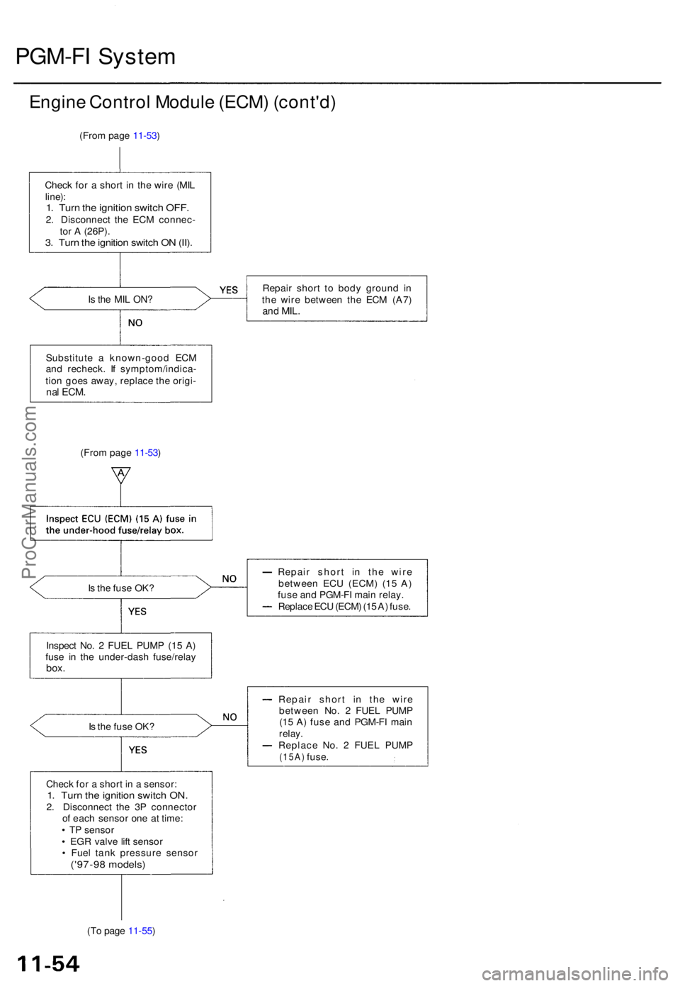
PGM-FI Syste m
Engine Contro l Modul e (ECM ) (cont'd )
(From pag e 11-53 )
Chec k fo r a shor t i n th e wir e (MI L
line) :1. Tur n th e ignitio n switc h OFF .2. Disconnec t th e EC M connec -
to r A (26P) .
3. Tur n th e ignitio n switc h O N (II) .
Is th e MI L ON ?Repai r shor t t o bod y groun d i n
th e wir e betwee n th e EC M (A7 )
and MIL .
Substitut e a known-goo d EC M
an d recheck . I f symptom/indica -
tio n goe s away , replac e th e origi -
nal ECM .
(From pag e 11-53 )
I s th e fus e OK ? Repai
r shor t i n th e wir e
betwee n EC U (ECM ) (1 5 A )
fus e an d PGM-F I mai n relay .
Replac e EC U (ECM ) (1 5 A ) fuse .
Inspec t No . 2 FUE L PUM P (1 5 A )
fus e i n th e under-das h fuse/rela y
box.
Is th e fus e OK ? Repai
r shor t i n th e wir e
betwee n No . 2 FUE L PUM P
(1 5 A ) fus e an d PGM-F I mai nrelay .Replac e No . 2 FUE L PUM P(15A) fuse.
Chec k fo r a shor t i n a sensor :
1. Tur n th e ignitio n switc h ON .2. Disconnec t th e 3 P connecto r
o f eac h senso r on e a t time :
• T P senso r
• EG R valv e lif t senso r
• Fue l tan k pressur e senso r
('97-98 models )
(To pag e 11-55 )
ProCarManuals.com
Page 885 of 1771
Starter Switc h Signa l
This signal s th e EC M whe n th e engin e is cranking .
NOTE: Transmissio n in o r position .
A (26P)ECM CONNECTOR S
Wir e sid e o t femal e terminal s
I s ther e batter y voltage ?
Is th e fus e OK ? Repai
r shor t i n th e wir e be -
twee n th e EC M (B5 ) an d th eNo . 9 STARTE R SIGNA L (7. 5
A ) fus e o r th e PGM-F I mai n
relay .Replac e th e No . 9 STARTE R
SIGNA L (7. 5 A ) fuse .
B (16P )
Inspectio n o f Starte r Switc h Sig -nal.
Chec k fo r a n ope n o r shor t i n th e
wir e (ST S line) :
Measur e voltag e betwee n EC M
connecto r terminal s B 5 an d A2 6on th e EC M connector s wit h th e
ignitio n switc h i n th e star t posi -
tion (III) .
Starte r switc h signa l i s OK . Inspec
t th e No . 9 STARTE R SIG -
NA L (7. 5 A ) fus e in th e under-das h
fuse/rela y box .
Repai r ope n in th e wir e betwee n
the EC M (B5 ) and th e No . 9STARTE R SIGNA L (7. 5 A ) fuse .
ProCarManuals.com
Page 915 of 1771

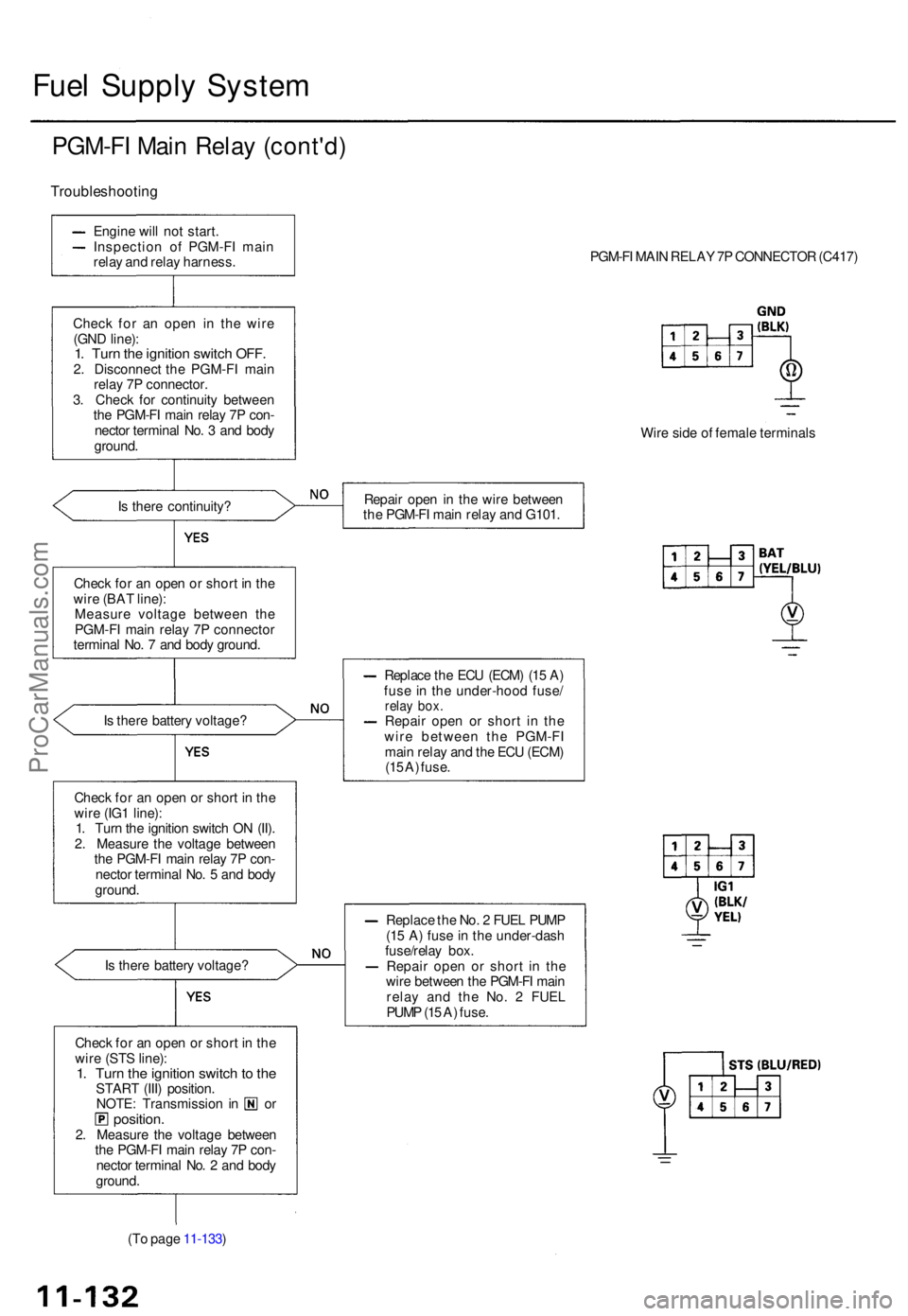
Fuel Suppl y Syste m
PGM-F I Mai n Rela y (cont'd )
Troubleshootin g
Engine wil l no t start .
Inspectio n o f PGM-F I mai n
rela y an d rela y harness .
Chec k fo r a n ope n i n th e wir e
(GN D line) :
1. Tur n th e ignitio n switc h OFF .2. Disconnec t th e PGM-F I mai n
rela y 7 P connector .
3 . Chec k fo r continuit y betwee n
th e PGM-F I mai n rela y 7 P con -
necto r termina l No . 3 an d bod y
ground .
I s ther e continuity ?
Chec k fo r a n ope n o r shor t i n th e
wir e (BA T line) :
Measur e voltag e betwee n th e
PGM-F I mai n rela y 7 P connecto r
termina l No . 7 an d bod y ground .
I s ther e batter y voltage ?
Chec k fo r a n ope n o r shor t i n th e
wir e (IG 1 line) :
1 . Tur n th e ignitio n switc h O N (II) .
2 . Measur e th e voltag e betwee n
th e PGM-F I mai n rela y 7 P con -
necto r termina l No . 5 an d bod y
ground .
I s ther e batter y voltage ?
Chec k fo r a n ope n o r shor t i n th e
wir e (ST S line) :
1. Tur n th e ignitio n switc h to th eSTAR T (III ) position .NOTE: Transmissio n i n o rposition .2. Measur e th e voltag e betwee n
th e PGM-F I mai n rela y 7 P con -
necto r termina l No . 2 an d bod y
ground .
(T o pag e 11-133 ) PGM-F
I MAI N RELA Y 7 P CONNECTO R (C417 )
Wir e sid e o f femal e terminal s
Repai r ope n in th e wir e betwee n
th e PGM-F I mai n rela y an d G101 .
Replac e th e EC U (ECM ) (1 5 A )
fus e i n th e under-hoo d fuse /
relay box .Repai r ope n o r shor t i n th e
wir e betwee n th e PGM-F I
mai n rela y an d th e EC U (ECM )
(1 5 A ) fuse .
Replac e th e No . 2 FUE L PUM P
(1 5 A ) fus e in th e under-das h
fuse/rela y box .
Repai r ope n o r shor t i n th e
wir e betwee n th e PGM-F I mai n
rela y an d th e No . 2 FUE L
PUM P (1 5 A ) fuse .
ProCarManuals.com
Page 916 of 1771

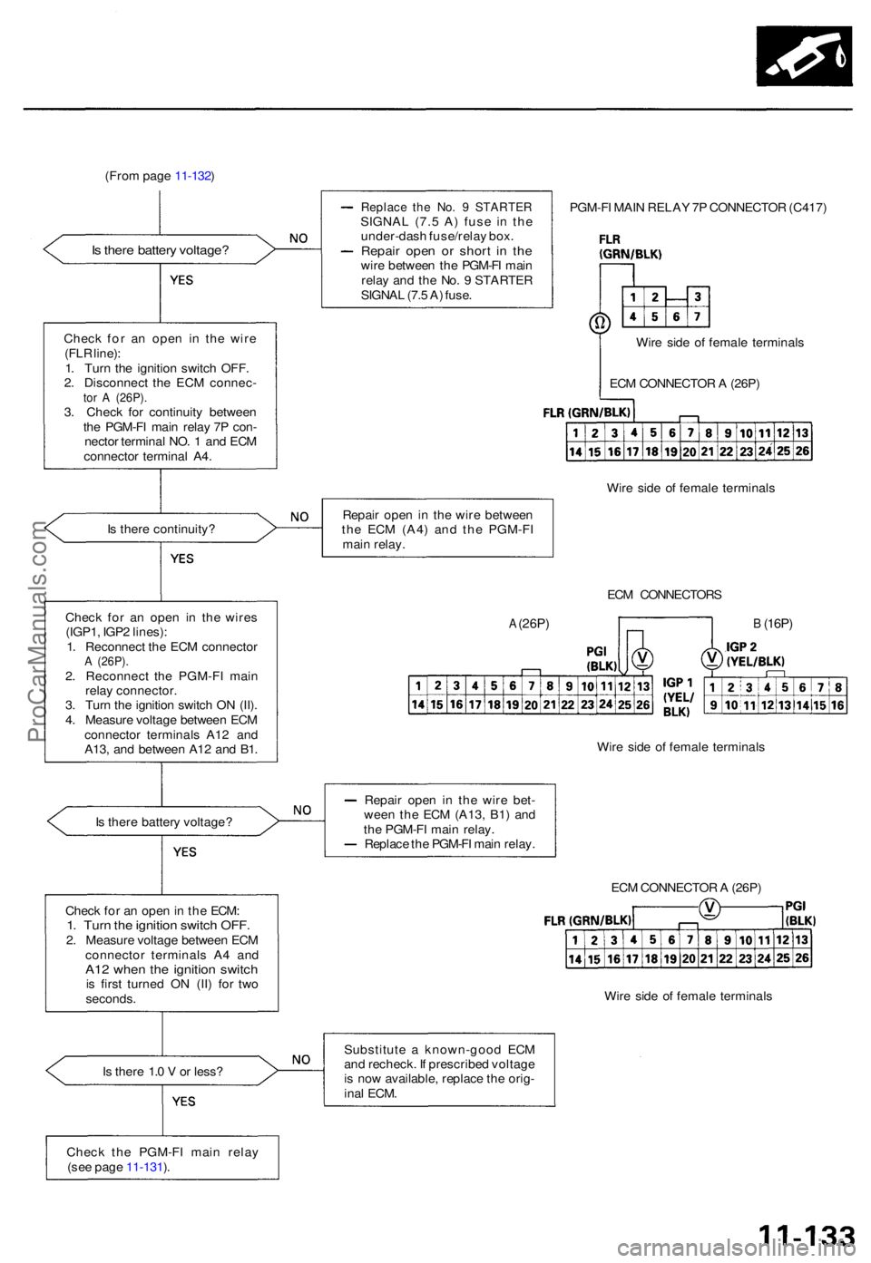
(From pag e 11-132 )
I s ther e 1. 0 V or less ?
Replac e th e No . 9 STARTE RSIGNAL (7. 5 A ) fus e i n th e
under-das h fuse/rela y box .
Repai r ope n o r shor t i n th ewir e betwee n th e PGM-F I mai n
rela y an d th e No . 9 STARTE R
SIGNA L (7. 5 A ) fuse . PGM-F
I MAI N RELA Y 7 P CONNECTO R (C417 )
Wir e sid e o f femal e terminal s
Repai r ope n i n th e wir e betwee n
th e EC M (A4 ) an d th e PGM-F I
mai n relay .
ECM CONNECTOR S
Wir e sid e o f femal e terminal s
Repai r ope n i n th e wir e bet -
wee n th e EC M (A13 , B1 ) an d
th e PGM-F I mai n relay .
Replac e th e PGM-F I mai n relay .
ECM CONNECTO R A (26P )
Wir e sid e o f femal e terminal s
Substitut e a known-goo d EC M
an d recheck . I f prescribe d voltag e
i s no w available , replac e th e orig -
ina l ECM .
Chec k th e PGM-F I mai n rela y
(se e pag e 11-131 ).
Chec
k fo r a n ope n in th e ECM :
1. Tur n th e ignitio n switc h OFF .2. Measur e voltag e betwee n EC M
connecto r terminal s A 4 an d
A12 whe n th e ignitio n switc his firs t turne d O N (II ) fo r tw o
seconds .
I
s ther e batter y voltage ?
Chec
k fo r a n ope n i n th e wire s
(IGP1 , IGP 2 lines) :
1 . Reconnec t th e EC M connecto r
A (26P) .2. Reconnec t th e PGM-F I mai n
rela y connector .
3 . Tur n th e ignitio n switc h O N (II) .
4 . Measur e voltag e betwee n EC M
connecto r terminal s A1 2 an d
A13 , an d betwee n A1 2 an d B1 .
I
s ther e continuity ? EC
M CONNECTO R A (26P )
B (16P)A (26P )
Wire sid e o f femal e terminal s
Chec
k fo r a n ope n i n th e wir e
(FL R line) :
1 . Tur n th e ignitio n switc h OFF .
2 . Disconnec t th e EC M connec -
tor A (26P) .3. Chec k fo r continuit y betwee n
th e PGM-F I mai n rela y 7 P con -
necto r termina l NO . 1 an d EC M
connecto r termina l A4 .
Is ther e batter y voltage ?
ProCarManuals.com