Page 44 of 1771
Engine Removal/Installatio n
Removal (cont'd )
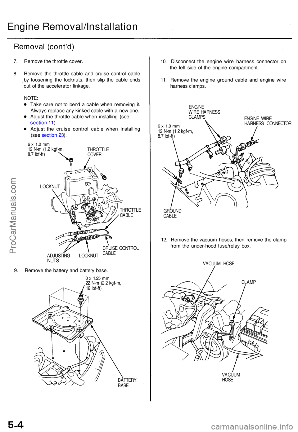
7. Remov e th e throttl e cover .
8.Remov e th e throttl e cabl e an d cruis e contro l cabl e
b y loosenin g th e locknuts , the n sli p th e cabl e end s
ou t o f th e accelerato r linkage .
NOTE:
Take car e no t t o ben d a cabl e whe n removin g it .
Alway s replac e an y kinke d cabl e wit h a ne w one .
Adjus t th e throttl e cabl e whe n installin g (se e
sectio n 11 ).
Adjus t th e cruis e contro l cabl e whe n installin g
(se e sectio n 23 ).
6 x 1. 0 m m12 N- m (1. 2 kgf-m ,
8. 7 Ibf-ft ) THROTTL
ECOVER
LOCKNU T
THROTTLE
CABLE
ADJUSTIN G LOCKNU TNUTS
CRUIS E CONTRO LCABLE
9. Remov e th e batter y an d batter y base .
8 x 1.2 5 mm22 N- m (2. 2 kgf-m ,
1 6 Ibf-ft )
BATTER YBASE
10. Disconnec t th e engin e wir e harnes s connecto r o n
th e lef t sid e o f th e engin e compartment .
11 . Remov e th e engin e groun d cabl e an d engin e wir e
harnes s clamps .
ENGINEWIRE HARNES S
CLAMP S
6 x 1. 0 m m12 N- m (1. 2 kgf-m ,
8. 7 Ibf-ft ) ENGIN
E WIR E
HARNES S CONNECTO R
GROUN D
CABLE
12. Remov e th e vacuu m hoses , the n remov e th e clam p
fro m th e under-hoo d fuse/rela y box .
VACUU M HOS E
CLAM P
VACUU M
HOS E
ProCarManuals.com
Page 45 of 1771
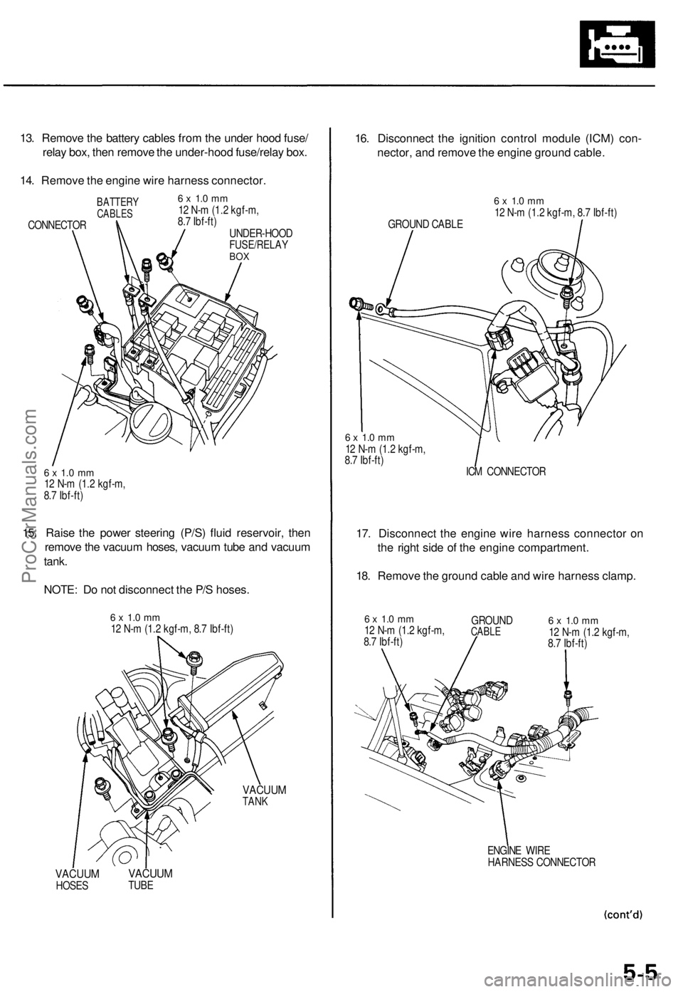
13. Remove the battery cables from the under hood fuse/
relay box, then remove the under-hood fuse/relay box.
14. Remove the engine wire harness connector.
BATTERY
CABLES
CONNECTOR
6 x 1.0 mm
12 N-m (1.2 kgf-m,
8.7 Ibf-ft)
UNDER-HOOD
FUSE/RELAY
BOX
6 x 1.0 mm
12 N-m (1.2 kgf-m,
8.7 Ibf-ft)
15. Raise the power steering (P/S) fluid reservoir, then
remove the vacuum hoses, vacuum tube and vacuum
tank.
NOTE: Do not disconnect the P/S hoses.
6 x 1.0 mm
12 N-m (1.2 kgf-m, 8.7 Ibf-ft)
VACUUM
TANK
VACUUM
HOSES
VACUUM
TUBE
16. Disconnect the ignition control module (ICM) con-
nector, and remove the engine ground cable.
GROUND CABLE
6 x 1.0 mm
12 N-m (1.2 kgf-m, 8.7 Ibf-ft)
6 x 1.0 mm
12 N-m (1.2 kgf-m,
8.7 Ibf-ft)
ICM CONNECTOR
17. Disconnect the engine wire harness connector on
the right side of the engine compartment.
18. Remove the ground cable and wire harness clamp.
6 x 1.0 mm
12 N-m (1.2 kgf-m,
8.7 Ibf-ft)
GROUND
CABLE
6 x 1.0 mm
12 N-m (1.2 kgf-m,
8.7 Ibf-ft)
ENGINE WIRE
HARNESS CONNECTORProCarManuals.com
Page 73 of 1771
Cylinder Head s
Remova l
Engine remova l i s no t require d fo r thi s procedure .
Mak e sur e jack s an d safet y stand s ar e
place d properl y an d hois t bracket s ar e attache d th e t o
correc t position s o n th e engine .
CAUTION :
Us e fende r cover s t o avoi d damagin g painte d sur -
faces .
Unplu g th e wirin g connector s carefull y whil e holdin g
th e connecto r portio n to avoi d damage .
T o avoi d damagin g th e cylinde r head , wai t unti l th e
engin e coolan t temperatur e drop s belo w 100° F (38°C )
befor e loosenin g th e retainin g bolts .
NOTE :
Mark al l wirin g an d hose s t o avoi d misconnection .
Also , b e sur e tha t the y d o no t contac t othe r wirin g o r
hoses , o r interfer e wit h othe r parts .
Inspec t th e timin g bel t befor e removin g th e cylinde r
head .
Tur n th e crankshaf t pulle y s o tha t th e No . 1 pisto n i s
a t to p dea d cente r (se e pag e 6-10 ).
1 . Mak e sur e yo u hav e th e anti-thef t cod e fo r th e
radio , the n writ e dow n th e frequencie s fo r th e
radio' s prese t buttons .
2 . Disconnec t th e batter y negativ e termina l first , the n
the positiv e terminal .
3. Drai n th e engin e coolan t (se e pag e 10-5 ).
4 . Remov e th e engin e cove r (se e pag e 5-3 ).
5 . Remov e th e intak e ai r duc t an d ai r cleane r housin g
assembl y (se e pag e 5-3 ).
6 . Remov e th e throttl e cove r (se e pag e 5-4 ).
7 . Remov e th e throttl e cabl e an d cruis e contro l cabl e
b y loosenin g th e locknuts , the n sli p th e cabl e end s
ou t o f th e accelerato r linkag e (se e pag e 5-4 ).
NOTE :
Take car e no t t o ben d a cabl e whe n removin g it .
Alway s replac e an y kinke d cabl e wit h a ne w one .
Adjus t th e throttl e cabl e whe n installin g (se e
sectio n 11 ).
Adjus t th e cruis e contro l cabl e whe n installin g
(se e sectio n 23 ). 8
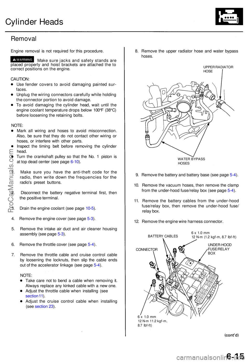
. Remov e th e uppe r radiato r hos e an d wate r bypas s
hoses.
UPPER RADIATO RHOSE
WATE R BYPAS SHOSES
9. Remov e th e batter y an d batter y bas e (se e pag e 5-4 ).
10 . Remov e th e vacuu m hoses , the n remov e th e clam p
fro m th e under-hoo d fuse/rela y bo x (se e pag e 5-4 ).
11 . Remov e th e batter y cable s fro m th e under-hoo d
fuse/rela y box , the n remov e th e under-hoo d fuse /
rela y box .
12 . Remov e th e engin e wir e harnes s connector .
BATTERY CABLE S
CONNECTO R
6 x 1. 0 m m12 N- m (1. 2 kgf-m , 8. 7 Ibf-ft )
UNDER-HOO DFUSE/RELAYBOX
6 x 1. 0 m m12 N- m 11. 2 kgf-m ,8.7 Ibf-ft )
ProCarManuals.com
Page 176 of 1771
System Descriptio n
System Connector s [Das h an d Floor ]
C427/C601
C61 3 C61
2DASHBOAR D
WIR E HARNES S
C482
C41 8
C41 7
REA RHARNES S
FUEL UNI TSUB-HARNES S
C773
C519/C77 1
MAIN WIR EHARNES SC429
REA R WIR EHARNES S
C603
C40 5
C41 5
UNDER-DAS HFUSE/RELAYBOX
C40 6
C40 4
C403
C40 2
ProCarManuals.com
Page 181 of 1771
II. Powertrain Control Module (PCM) Reset Procedure
Either of the following actions will reset the PCM
Use the OBD II scan tool or Honda PGM Tester to clear the PCM's memory.
NOTE: See the OBD II scan tool or Honda PGM Tester user's manuals for specific operating instructions.
Turn the ignition switch OFF. Remove the BACK UP RADIO (10 A) fuse from the under-hood fuse/relay box for
10 seconds.
BACK UP RADIO
(10 A) FUSE
UNDER-HOOD
FUSE/RELAY
BOX
III. Final Procedure (this procedure must be done after any troubleshooting)
1. Remove the SCS Service Connector if it is connected.
NOTE: If the SCS service connector is connected and there are no DTCs stored in the PCM, the MIL will stay
on when the ignition switch is turned ON (II).
2. Do the PCM Reset Procedure.
3. Turn the ignition switch OFF.
4. Disconnect the OBD II scan tool or Honda PGM Tester from the Data Link Connector (16P).ProCarManuals.com
Page 201 of 1771
Powertrain Control Module (PCM)
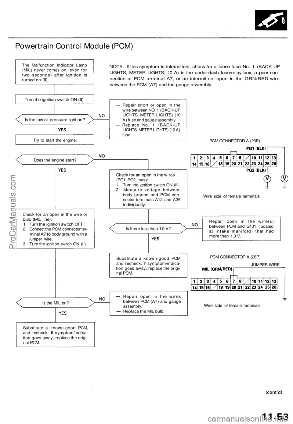
NOTE: If this symptom is intermittent, check for a loose fuse No. 1 (BACK UP
LIGHTS, METER LIGHTS, 10 A) in the under-dash fuse/relay box, a poor con-
nection at PCM terminal A7, or an intermittent open in the GRN/RED wire
between the PCM (A7) and the gauge assembly.
Is the low oil pressure light on?
Try to start the engine.
Does the engine start?
Check for an open in the wire or
bulb (MIL line):
1. Turn the ignition switch OFF.
2. Connect the PCM connector ter-
minal A7 to body ground with a
jumper wire.
3. Turn the ignition switch ON (II).
Is the MIL on?
Substitute a known-good PCM,
and recheck. If symptom/indica-
tion goes away, replace the origi-
nal
PCM.
— Repair short or open in the
wire between NO. 1 (BACK-UP
LIGHTS, METER LIGHTS) (10
A) fuse and gauge assembly.
— Replace No. 1 (BACK-UP
LIGHTS, METER LIGHTS) (10 A)
fuse.
PCM CONNECTOR A (26P)
Check for an open in the wires
(PG1, PG2 lines):
1. Turn the ignition switch ON (II).
2. Measure voltage between
body ground and PCM con-
nector terminals A12 and A25
individually.
Wire side of female terminals
Is there less than 1.0 V?
Repair open in the wire(s)
between PCM and G101 (located
at intake manifold) that had
more than 1.0 V.
PCM CONNECTOR A (26P)
JUMPER WIRE
Wire side of female terminals
Repair open in the wires
between PCM (A7) and gauge
assembly.
Replace the MIL bulb.
Substitute a known-good PCM
and recheck. If symptom/indica-
tion goes away, replace the origi-
nal
PCM.
Turn the ignition switch ON (II).
The Malfunction Indicator Lamp
(MIL) never comes on (even for
two seconds) after ignition is
turned on (II).ProCarManuals.com
Page 203 of 1771
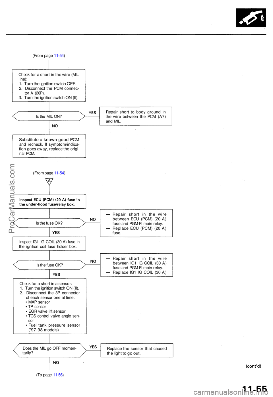
(From pag e 11-54 )
Chec k fo r a shor t i n th e wir e (MI L
line) :
1. Tur n th e ignitio n switc h OFF .2. Disconnec t th e PC M connec -tor A (26P) .3. Tur n th e ignitio n switc h O N (II) .
Is th e MI L ON ?Repai r shor t t o bod y groun d i n
th e wir e betwee n th e PC M (A7 )
and MIL .
Substitut e a known-goo d PC Mand recheck . I f symptom/indica -
tio n goe s away , replac e th e origi -
nal PCM .
(From pag e 11-54 )
I s th e fus e OK ?
Inspec t IG 1 I G COI L (3 0 A ) fus e in
th e ignitio n coi l fus e holde r box . Repai
r shor t i n th e wir e
betwee n EC U (PCM ) (2 0 A )
fus e an d PGM-F I mai n relay .
Replac e EC U (PCM ) (2 0 A )
fuse .
Is th e fus e OK ? Repai
r shor t i n th e wir e
betwee n IG 1 I G COI L (3 0 A )
fus e an d PGM-F I mai n relay .
Replac e IG 1 I G COI L (3 0 A )
Chec k fo r a shor t i n a sensor :
1. Tur n th e ignitio n switc h O N (II) .2. Disconnec t th e 3 P connecto r
o f eac h senso r on e a t time :
MA P senso r
T P senso r
EG R valv e lif t senso r
TC S contro l valv e angl e sen -
sorFue l tan k pressur e senso r('97-98 models )
Does th e MI L g o OF F momen -
tarily ? Replac
e th e senso r tha t cause dthe ligh t t o g o out .
(To pag e 11-56 )
ProCarManuals.com
Page 210 of 1771
Starter Switch Signal
This signals the PCM when the engine is cranking.
PCM CONNECTORS
A
(26P)
C
(12P)
Wire side of female terminals
Is there battery voltage?
Is the fuse OK?
Repair short in the wire be-
tween the PCM (C6) and the
No. 9 STARTER SIGNAL (7.5
A) fuse or the PGM-FI main
relay.
Replace the No. 9 STARTER
SIGNAL (7.5 A) fuse.
Repair open in the wire between
the PCM
(C6)
and the No. 9
STARTER SIGNAL (7.5 A) fuse.
Starter switch signal is OK.
Inspect the No. 9 STARTER SIG-
NAL (7.5 A) fuse in the under-dash
fuse/relay box.
Check for an open or short in the
wire (STS line):
Measure voltage between PCM
connector terminals C6 and A26
with the ignition switch in the
start position (III).
Inspection of Starter Switch Sig-
nal.
NOTE: Transmission in or position.ProCarManuals.com