Page 917 of 1771
Intake Air System
System Description
The system supplies air for all engine needs. It consists of the intake air pipe, Air Cleaner (ACL), intake air duct. Throttle
Body (TB), Idle Air Control (IAC) Valve, fast idle thermo valve, and intake manifold.
A resonator in the intake air pipe provides additional silencing as air is drawn into the system.
IAB CONTROL
SOLENOID VALVE
IAB
CHECK
VALVE
IAB
CONTROL
DIAPHRAGM
From No. 4 ECU
(ECM) ('95 - 96 models: 15A,
'97-98 models: 20A)
FUSE
(in the under-dash
fuse/relay box)
From PGM-FI
MAIN RELAY
VARIOUS
SENSORS
IAB
VACUUM TANK
THROTTLE
BODY
INTAKE
AIR DUCT
ACL
INTAKE
MANIFOLD
IDLE
ADJUSTING
SCREW
FAST
IDLE
THERMO
VALVE
RESONATOR
INTAKE
AIR
PIPE
IAC VALVE
ENGINE
COOLANT
ENGINE
COOLANT
IAB
VALVE
ECMProCarManuals.com
Page 923 of 1771
Intake Air Bypass (IAB) Control System
Description
Two air intake paths are provided in the intake manifold to allow the selection of the intake path most favorable for a
given engine speed. Satisfactory power performance is achieved by closing and opening the intake Air Bypass (IAB)
valves. High torque at low rpm is achieved when the IAB valves are closed, whereas high power at high rpm is achieved
when the IAB valves are opened.
IAB CONTROL
DIAPHRAGM
From No. 4 ECU (ECM)
('95-96 models: 15A,
'97 - 98 models: 20A) FUSE
(In the under-dash
fuse/relay box)
VARIOUS
SENSORS
IAB
CONTROL
SOLENOID
VALVE
IAB VACUUM TANK
IAB CONTROL SOLENOID VALVE OFF
ENGINE RPM IS ABOVE 4,800 rpmProCarManuals.com
Page 925 of 1771

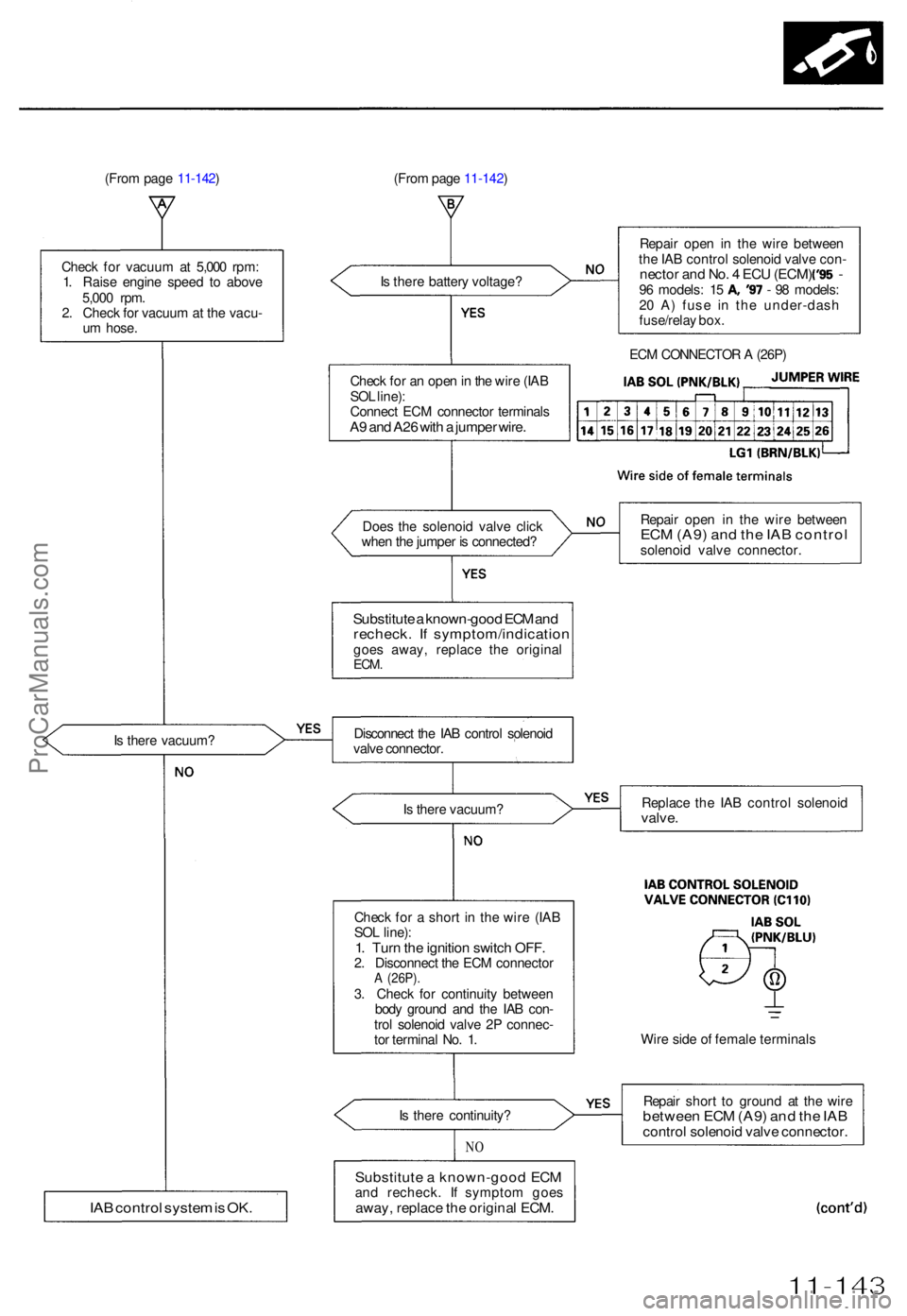
(From pag e 11-142 ) (From pag e 11-142 )
I s ther e batter y voltage ? Repai
r ope n i n th e wir e betwee n
th e IA B contro l solenoi d valv e con -
necto r an d No . 4 EC U (ECM ) ('95 -96 models : 1 5 A , '9 7 - 9 8 models :
2 0 A ) fus e i n th e under-das h
fuse/rela y box .
Chec k fo r a n ope n in th e wir e (IA B
SO L line) :
Connec t EC M connecto r terminal s
A9 an d A2 6 wit h a jumpe r wire .
Doe s th e solenoi d valv e clic k
whe n th e jumpe r i s connected ?
Substitute a known-goo d EC M an drecheck . I f symptom/indicatio ngoes away , replac e th e origina lECM.
Is ther e vacuum ?
Chec k fo r a shor t i n th e wir e (IA B
SO L line) :
1. Tur n th e ignitio n switc h OFF .2. Disconnec t th e EC M connecto rA (26P) .3. Chec k fo r continuit y betwee n
bod y groun d an d th e IA B con -
tro l solenoi d valv e 2 P connec -
to r termina l No . 1 .
I s ther e continuity ?
NO
Substitut e a known-goo d EC Mand recheck . I f sympto m goe saway, replac e th e origina l ECM .
Repai r ope n i n th e wir e betwee nECM (A9 ) an d th e IA B contro lsolenoid valv e connector .
Replac e th e IA B contro l solenoi d
valve.
Wire sid e o f femal e terminal s
Repai r shor t t o groun d a t th e wir e
betwee n EC M (A9 ) an d th e IA Bcontro l solenoi d valv e connector .
11-143
Check fo r vacuu m a t 5,00 0 rpm :
1 . Rais e engin e spee d t o abov e
5,00 0 rpm .
2 . Chec k fo r vacuu m a t th e vacu -
u m hose .
I s ther e vacuum ? Disconnec
t th e IA B contro l solenoi d
valv e connector .
IAB contro l syste m is OK .
ECM CONNECTO R A (26P )
ProCarManuals.com
Page 928 of 1771

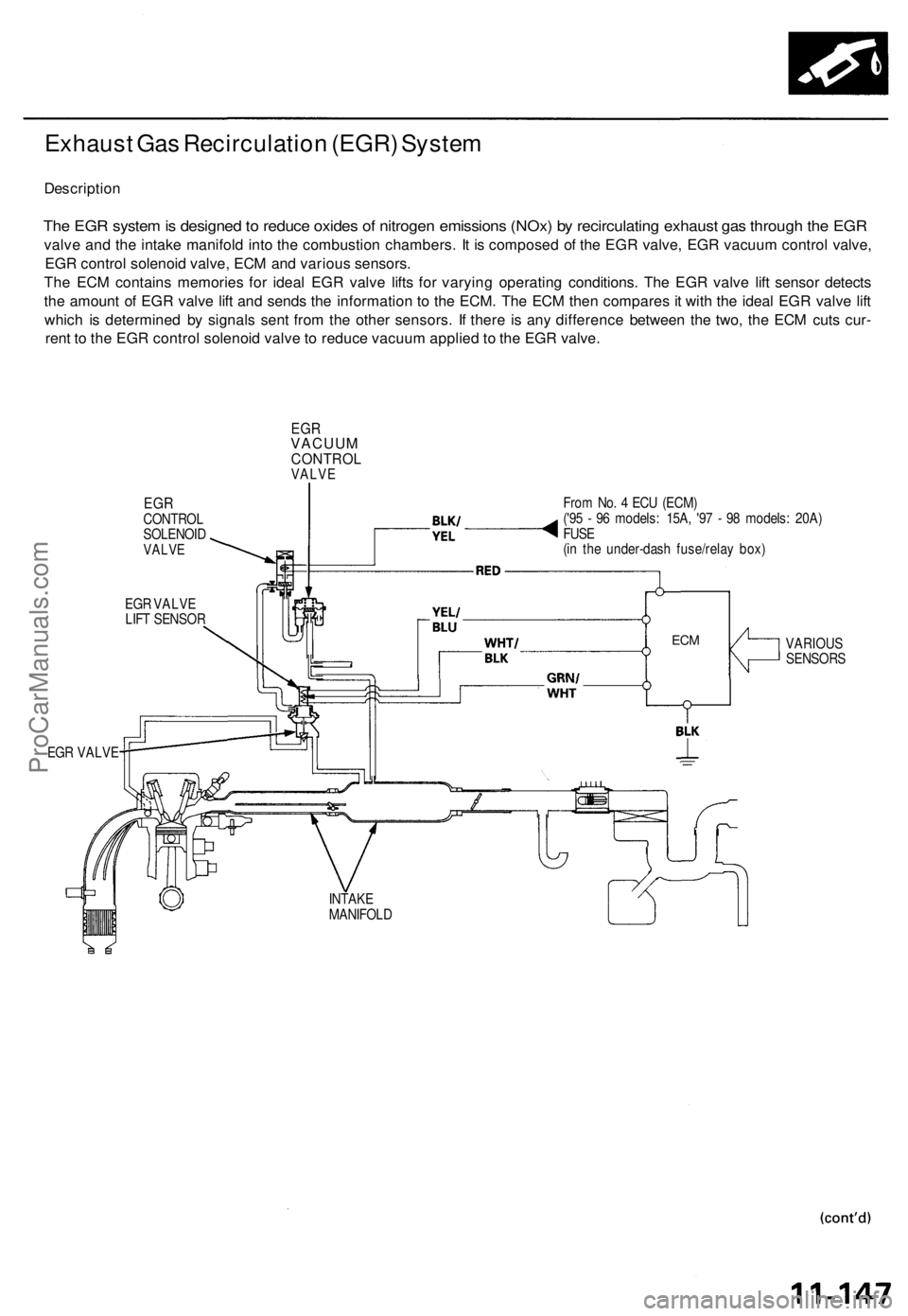
Exhaust Ga s Recirculatio n (EGR ) Syste m
Descriptio n
The EG R syste m is designe d to reduc e oxide s o f nitroge n emission s (NOx ) b y recirculatin g exhaus t ga s throug h th e EG R
valv e an d th e intak e manifol d int o th e combustio n chambers . I t i s compose d o f th e EG R valve , EG R vacuu m contro l valve ,
EG R contro l solenoi d valve , EC M an d variou s sensors .
Th e EC M contain s memorie s fo r idea l EG R valv e lift s fo r varyin g operatin g conditions . Th e EG R valv e lif t senso r detect s
th e amoun t o f EG R valv e lif t an d send s th e informatio n t o th e ECM . Th e EC M the n compare s it wit h th e idea l EG R valv e lif t
whic h i s determine d b y signal s sen t fro m th e othe r sensors . I f ther e i s an y differenc e betwee n th e two , th e EC M cut s cur -
ren t t o th e EG R contro l solenoi d valv e to reduc e vacuu m applie d to th e EG R valve .
EGRVACUU MCONTRO LVALVE
EGRCONTRO L
SOLENOI D
VALVE
EGR VALV E
LIF T SENSO R Fro
m No . 4 EC U (ECM )
('9 5 - 9 6 models : 15A , '9 7 - 9 8 models : 20A )
FUS E
(i n th e under-das h fuse/rela y box )
VARIOU S
SENSOR S
EG R VALV E
INTAKE
MANIFOL D
ECM
ProCarManuals.com
Page 931 of 1771
'95 - 96 models:
VARIOUS
SENSORS
From
No. 4 ECU
(ECM)
(20A) FUSE
(in the under-dash
fuse/relay box)
VARIOUS
SENSORS
EVAP
TWO WAY
VALVE
EVAP
BYPASS
SOLENOID
VALVE
EVAP
THREE
WAY
VALVE
EVAP CONTROL
CANISTER
VENT SHUT VALVE
EVAP PURGE
CONTROL
SOLENOID VALVE
ECM
ECM
From
No. 4 ECU
(ECM) (15A)
FUSE (in the under-dash
fuse/relay box)
EVAP CONTROL
CANISTER
FUEL
TANK
PRESSURE
SENSOR
FUEL TANK
FUEL FILL
CAP
FUEL TANK
EVAP VALVE
FUEL TANK
'97 - 98 models:
FUEL TANK
EVAP VALVE
EVAP TWO WAY VALVE
FRESH
AIR
FUEL FILL CAP
EVAP PURGE
FLOW SWITCH
EVAP PURGE
CONTROL
SOLENOID VALVEProCarManuals.com
Page 975 of 1771

Troubleshooting Procedures
Checking the Diagnostic Trouble Code (DTC)
with an OBD II Scan tool or Honda PGM Tester
When the TCM senses an abnormality in the input or output systems, the indicator light in the gauge assembly will
blink. When the 16P Data Link Connector (DLC) (located behind the ashtray) is connected to the OBD II Scan Tool or Honda
PGM Tester as shown, the scan tool or tester will indicate the Diagnostic Trouble Code (DTC) when the ignition switch is
turned ON(II).
When the indicator light has been reported on, connect the OBD II Scan Tool conforming to SAE J1978 or Honda PGM
Tester to the DLC (16P) behind the ashtray. Turn the ignition switch on (II), and observe the DTC on the screen of the OBD II
Scan Tool or Honda PGM Tester. After determining the DTC, refer to the electrical system Symptom-to-Component Chart
on page 14-56 and 14-57.
NOTE: See the OBD II Scan Tool or Honda PGM Tester user's manual for specific instruction.
OBD II SCAN TOOL or
HONDA PGM TESTER
Some PGM-FI problems will also make the indicator light come on. After repairing the PGM-FI system, disconnect the
BACK UP RADIO fuse (10 A) in the under-hood fuse/relay box for more than 10 seconds to reset the TCM memory, then
retest.
NOTE: Disconnecting the BACK UP RADIO fuse also cancels the radio anti-theft code, preset stations and the clock setting.
Get the customer's code number, and make note of the radio presets before removing the fuse so you can reset them.
DATA LINK CONNECTOR (16P)ProCarManuals.com
Page 978 of 1771

4. Inspec t th e circui t o n th e TC M accordin g t o th e trou -
bleshootin g flowchar t wit h th e specia l tool s an d a
digita l multimete r a s shown .
How to us e th e Backprob e Se t
Connec t th e backprob e adapter s t o th e stackin g patc h
cords , an d connec t th e cord s t o a multimeter . Usin g
th e wir e insulatio n a s a guid e fo r th e contoure d ti p o f
the backprob e adapter , gentl y slid e th e ti p int o th e
connecto r fro m th e wir e sid e unti l i t come s i n contac t
with th e termina l en d o f th e wire .
BACKPROB E SE T07SAZ-001000 A
(tw o required )
BACKPROB EADAPTER
STACKIN GPATCH COR D
TCM
DIGITA L MULTIMETE R
(Commerciall y available )
KS-AHM-32-003 ,or equivalen t
TCM Rese t Procedur e
1 . Mak e sur e yo u hav e th e anti-thef t cod e fo r th e radio ,
the n writ e dow n th e frequencie s fo r th e radio' s pre -
set buttons .
2. Tur n th e ignitio n switc h OFF .
3 . Remov e th e No . 3 9 BAC K U P RADI O fus e (1 0 A )
fro m th e under-hoo d fuse/rela y bo x fo r 1 0 second s
t o rese t th e TCM .
NOTE : Th e TC M memor y canno t b e cleare d b y
usin g th e OB D II Sca n Too l o r Hond a PG M Tester ; b e
sur e to remov e th e BAC K U P RADI O fus e to rese t th e
TCM .
BACK U P RADI O
(1 0 A ) FUS E
UNDER-HOO D
FUSE/RELAYBOX
Fina l Procedur e
NOTE : Thi s procedur e mus t b e don e afte r an y trouble -
shooting.
1. Tur n th e ignitio n switc h OFF .
2 . Disconnec t th e OB D II Sca n Too l o r Hond a PG M
Teste r fro m th e Dat a Lin k Connector , o r remov e th e
specia l too l fro m th e Servic e Chec k Connector .
3. Rese t th e TCM .
4. Tur n th e ignitio n switc h O N (II) .
5 . Ente r th e anti-thef t cod e fo r th e radio , the n ente r th e
customer' s radi o statio n presets .
ProCarManuals.com
Page 1295 of 1771
Component Locations
ABS CONTROL UNIT
UNDER-DASH RELAY BOX
RIGHT-FRONT WHEEL
SENSOR CONNECTOR
UNDER-HOOD
FUSE/RELAY BOX
SERVICE CHECK CONNECTOR (2P)
ABS INSPECTION CONNECTOR (6P)
MODULATOR UNIT
UNDER-HOOD ABS
FUSE/RELAY BOX
RIGHT-REAR WHEEL SENSOR
RIGHT-REAR WHEEL
SENSOR CONNECTOR
LEFT-REAR
WHEEL SENSOR
LEFT-REAR WHEEL
SENSOR CONNECTOR
RIGHT-FRONT
WHEEL SENSOR
LEFT FRONT WHEEL
SENSOR CONNECTOR
PARKING BRAKE SWITCH
UNDER-DASH FUSE/RELAY BOX
LEFT-FRONT WHEEL SENSORProCarManuals.com