Page 253 of 1771

Evaporative Emission (EVAP) Controls
Description
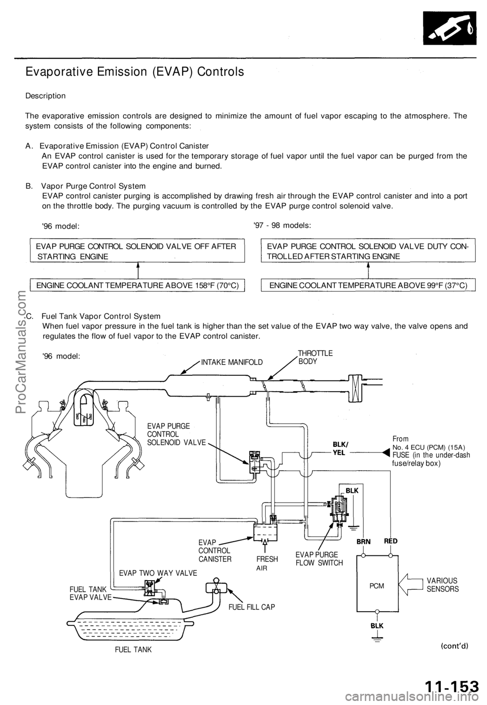
The evaporative emission controls are designed to minimize the amount of fuel vapor escaping to the atmosphere. The
system consists of the following components:
A. Evaporative Emission (EVAP) Control Canister
An EVAP control canister is used for the temporary storage of fuel vapor until the fuel vapor can be purged from the
EVAP control canister into the engine and burned.
B. Vapor Purge Control System
EVAP control canister purging is accomplished by drawing fresh air through the EVAP control canister and into a port
on the throttle body. The purging vacuum is controlled by the EVAP purge control solenoid valve.
'96 model:
'97 - 98 models:
C. Fuel Tank Vapor Control System
When fuel vapor pressure in the fuel tank is higher than the set value of the EVAP two way valve, the valve opens and
regulates the flow of fuel vapor to the EVAP control canister.
'96 model:
INTAKE MANIFOLD
THROTTLE
BODY
EVAP PURGE
CONTROL
SOLENOID VALVE
FUEL TANK
EVAP VALVE
EVAP TWO WAY VALVE
From
No. 4 ECU
(PCM) (15A)
FUSE (in the under-dash
fuse/relay box)
EVAP
CONTROL
CANISTER FRESH
AIR
EVAP PURGE
FLOW SWITCH
FUEL FILL CAP
PCM
VARIOUS
SENSORS
FUEL TANK
ENGINE COOLANT TEMPERATURE ABOVE 158°F (70°C)
ENGINE COOLANT TEMPERATURE ABOVE 99°F (37°C)
EVAP PURGE CONTROL SOLENOID VALVE DUTY CON-
TROLLED AFTER STARTING ENGINE
EVAP PURGE CONTROL SOLENOID VALVE OFF AFTER
STARTING ENGINEProCarManuals.com
Page 254 of 1771
Emission Contro l Syste m
Evaporativ e Emissio n (EVAP ) Control s (cont'd )
'97 - 9 8 models :
INTAKE
MANIFOL DTHROTTL EBODY
FromNo. 4 EC U (PCM )(20 A ) FUS E
(i n th e under-das h
fuse/rela y box )
EVAP CONTROL CANISTERVENT SHUT VALVE
EVAP TWO WAY VALVE
EVAPCONTROLCANISTER
VARIOU SSENSOR S
EVAP BYPAS SSOLENOI D VALV E
FUEL TAN K
FUE L TAN K
PRESSUR E
SENSO RFUE
L TAN K
EVA P VALV E FUE
L FIL L CA P
PCM
EVA P PURG ECONTRO LSOLENOI D VALV E
EVAP THRE EWAY VALV E
ProCarManuals.com
Page 308 of 1771
PCM Reset Procedure
1. Make sure you have the anti-theft code for the radio, then write down the frequencies for the radio's preset buttons.
2. Turn the ignition switch OFF.
3. Remove the BACK UP, RADIO fuse (10 A) from the under-hood fuse/relay box for 10 seconds to reset the PCM.
NOTE: The PCM memory can also be cleared by using the OBD II Scan Tool or Honda PGM Tester.
BACK UP, RADIO
(10 A) FUSE
UNDER-HOOD
FUSE/RELAY
BOX
Final Procedure
NOTE: This procedure must be done after any troubleshooting.
1. Turn the ignition switch OFF.
2. Disconnect the OBD II Scan Tool or Honda PGM Tester from the Data Link Connector (16P), or remove the special tool
from the Service Check Connector.
3. Reset the PCM.
4. Turn the ignition switch ON (II).
5. Enter the anti-theft code for the radio, then enter the customer's radio station presets.ProCarManuals.com
Page 511 of 1771
DTC Indication Pattern (When the ABS control unit detected a problem three times.):
Turn the ignition
switch ON (II)
ABS
Indicator
light on
ABS
Indicator
light off
DTC:
4-2
Main Coda: 4
Sub-Code: 2
Connect the
SCS service
connector
2 Second Second
pause pause
5 Second
pause
1
Second
pause
5 Second
pause
1
Second
pause
2 Seconds
• Turn the ignition switch ON (II). The ABS indicator light comes on for two seconds to check the bulb.
• The ABS control unit indicates the DTC three times.
• If you miscount the blinking frequency or if you recheck the blinking frequency, turn the ignition switch OFF then
turn it ON (II) to cycle the ABS indicator light again.
4. Remove the SCS service connector.
NOTE: The Malfunction Indicator Lamp (MIL) will stay on after the engine is started if the SCS service connector is
connected.
5. Remove the ABS B2 (15 A) fuse in the under-hood fuse/relay box for at least three seconds to erase the ABS control
unit's memory.ProCarManuals.com
Page 562 of 1771

Troubleshooting
Radiator Fan Control Module Input Tests
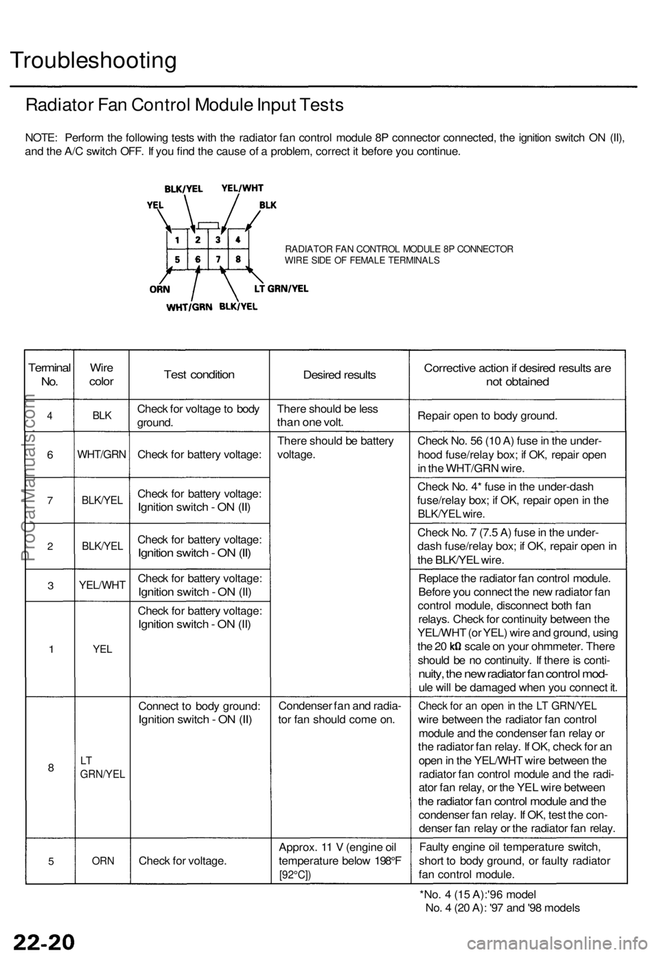
NOTE: Perform the following tests with the radiator fan control module 8P connector connected, the ignition switch ON (II),
and the A/C switch OFF. If you find the cause of a problem, correct it before you continue.
RADIATOR FAN CONTROL MODULE 8P CONNECTOR
WIRE SIDE OF FEMALE TERMINALS
Terminal
No.
4
6
7
2
3
1
8
5
Wire
color
BLK
WHT/GRN
BLK/YEL
BLK/YEL
YEL/WHT
YEL
LT
GRN/YEL
ORN
Test condition
Check for voltage to body
ground.
Check for battery voltage:
Check for battery voltage:
Ignition switch - ON (II)
Check for battery voltage:
Ignition switch - ON (II)
Check for battery voltage:
Ignition switch - ON (II)
Check for battery voltage:
Ignition switch - ON (II)
Connect to body ground:
Ignition switch - ON (II)
Check for voltage.
Desired results
There should be less
than one volt.
There should be battery
voltage.
Condenser fan and radia-
tor fan should come on.
Approx. 11 V (engine oil
temperature below 198°F
[92°C])
Corrective action if desired results are
not obtained
Repair open to body ground.
Check No. 56 (10 A) fuse in the under-
hood fuse/relay box; if OK, repair open
in the WHT/GRN wire.
Check No. 4* fuse in the under-dash
fuse/relay box; if OK, repair open in the
BLK/YEL wire.
Check No. 7 (7.5 A) fuse in the under-
dash fuse/relay box; if OK, repair open in
the BLK/YEL wire.
Replace the radiator fan control module.
Before you connect the new radiator fan
control module, disconnect both fan
relays. Check for continuity between the
YEL/WHT (or YEL) wire and ground, using
the 20 scale on your ohmmeter. There
should be no continuity. If there is conti-
nuity, the new radiator fan control mod-
ule will be damaged when you connect it.
Check for an open in the LT GRN/YEL
wire between the radiator fan control
module and the condenser fan relay or
the radiator fan relay. If OK, check for an
open in the YEL/WHT wire between the
radiator fan control module and the radi-
ator fan relay, or the YEL wire between
the radiator fan control module and the
condenser fan relay. If OK, test the con-
denser fan relay or the radiator fan relay.
Faulty engine oil temperature switch,
short to body ground, or faulty radiator
fan control module.
*No. 4 (15 A):'96 model
No. 4 (20 A): '97 and '98 modelsProCarManuals.com
Page 618 of 1771

Back-up Light s
Test
NOTE : Befor e testing , chec k th e No . 1 (1 0 A ) fus e i n th e
under-das h fuse/rela y box .
1. Chec k whethe r th e back-u p light s g o o n b y turnin g
the ignitio n switc h O N (II ) an d shiftin g th e shif t leve r
• I f th e back-u p light s d o no t g o on , chec k for :
blow n bulb .
faulty A/ T revers e relay ,
poo r groun d (G301 , G502) .
an ope n in th e wire .
• I f th e back-u p light s g o on , g o t o ste p 2 .
2. Wit h th e shif t leve r i n tur n th e ignitio n
switch OFF .
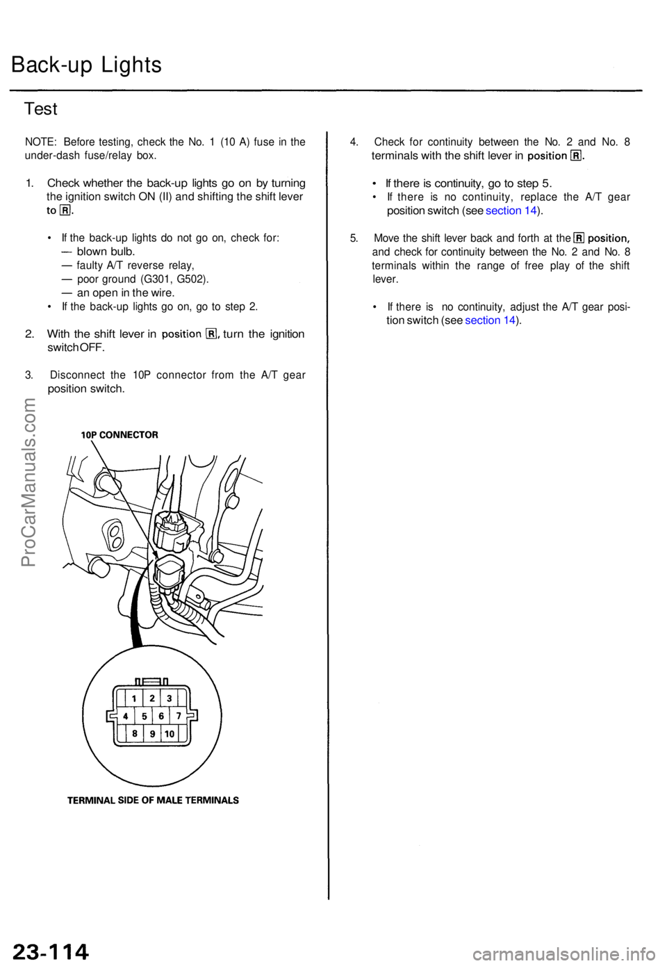
3. Disconnec t th e 10 P connecto r fro m th e A/ T gea r
positio n switch .
4. Chec k fo r continuit y betwee n th e No . 2 an d No . 8
terminal s wit h th e shif t leve r i n
• I f ther e is continuity , g o to ste p 5.
• I f ther e i s n o continuity , replac e th e A/ T gea r
positio n switc h (se e sectio n 14 ).
5 . Mov e th e shif t leve r bac k an d fort h a t th e
an d chec k fo r continuit y betwee n th e No . 2 an d No . 8
terminal s withi n th e rang e o f fre e pla y o f th e shif t
lever .
• I f ther e i s n o continuity , adjus t th e A/ T gea r posi -
tion switc h (se e sectio n 14 ).
ProCarManuals.com
Page 634 of 1771
Troubleshooting
NOTE:
• The numbers in the table show the troubleshooting sequence.
• Before troubleshooting,
Check the No. 1 (10 A) and the No. 4 (15 A)*1 or (20 A)*2 fuses in the under-dash fuse/relay box, and the No. 31 (120 A),
No. 35 (50 A), and the No. 30 (20 A) fuses in the under-hood fuse/relay box.
Check that the horns sound.
Check the tachometer to see if it works properly.ProCarManuals.com
Page 640 of 1771
Security Alar m Syste m
Componen t Locatio n Inde x
HORN (LOW ) HOR
N RELA Y NOTE
: Refe r t o page 23-274 of the '95-9 8
Acura 2.5TL Servic e Manual , P/ N 61SW504 ,for the items no t show n in thi s sub-section .
BATTERYTest, pag e 23-5 6
HEADLIGH T RELA Y
TAILLIGH T RELA Y
Test , pag e 23-5 8
UNDER-HOO
D
FUSE/RELAYBOX
DIMME R RELA Y
UNDER-DAS H RELA Y BO X
HOR N (HIGH )
Test , pag e 23-203
Test, pag e 23- 63 Test
, pag e 23-63
Test
, pag e 23-203 Test
, pag e 23- 62
ProCarManuals.com