Page 1550 of 1771

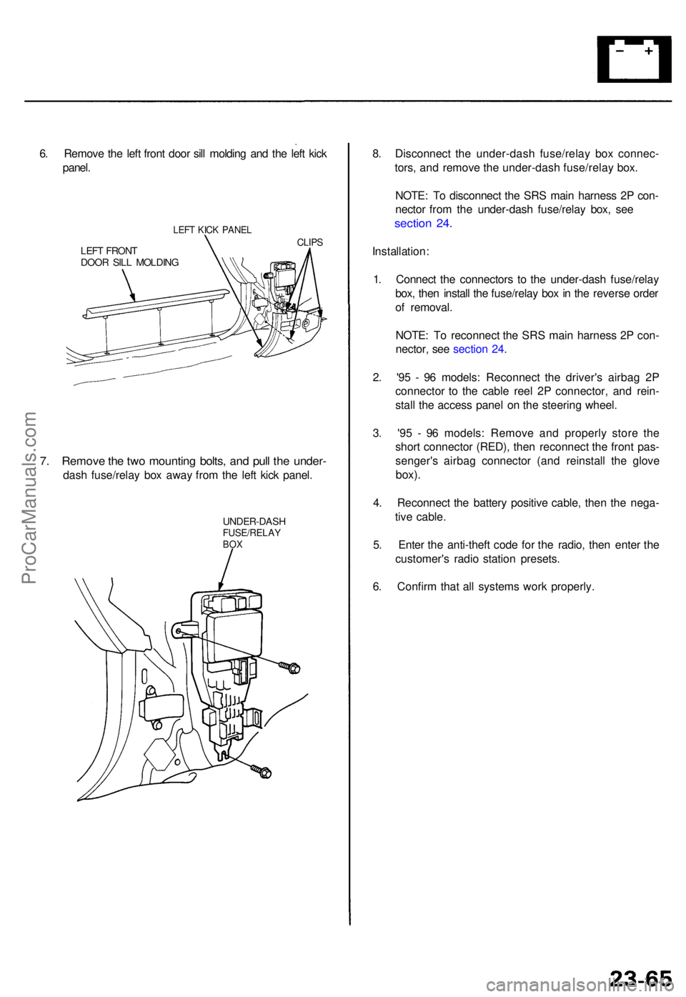
6. Remov e th e lef t fron t doo r sil l moldin g an d th e lef t kic k
panel .
LEFT KIC K PANE L
LEFT FRON TDOOR SIL L MOLDIN G
CLIPS
7. Remov e th e tw o mountin g bolts , an d pul l th e under -
dash fuse/rela y bo x awa y fro m th e lef t kic k panel .
UNDER-DAS HFUSE/RELAYBOX
8. Disconnec t th e under-das h fuse/rela y bo x connec -
tors , an d remov e th e under-das h fuse/rela y box .
NOTE : T o disconnec t th e SR S mai n harnes s 2 P con -
necto r fro m th e under-das h fuse/rela y box , se e
sectio n 24 .
Installation :
1 . Connec t th e connector s t o th e under-das h fuse/rela y
box , the n instal l th e fuse/rela y bo x in th e revers e orde r
o f removal .
NOTE : T o reconnec t th e SR S mai n harnes s 2 P con -
nector , se e sectio n 24 .
2 . '9 5 - 9 6 models : Reconnec t th e driver' s airba g 2 P
connecto r t o th e cabl e ree l 2 P connector , an d rein -
stal l th e acces s pane l o n th e steerin g wheel .
3 . '9 5 - 9 6 models : Remov e an d properl y stor e th e
shor t connecto r (RED) , the n reconnec t th e fron t pas -
senger' s airba g connecto r (an d reinstal l th e glov e
box).
4. Reconnec t th e batter y positiv e cable , the n th e nega -
tiv e cable .
5 . Ente r th e anti-thef t cod e fo r th e radio , the n ente r th e
customer' s radi o statio n presets .
6 . Confir m tha t al l system s wor k properly .
ProCarManuals.com
Page 1551 of 1771

Ignition Switc h
Test
SRS component s ar e locate d in thi s area . Revie w th e SR S
componen t locations , precautions , an d procedure s i n th e
SR S (sectio n 24 ) befor e performin g repair s o r service .
1 . Remov e th e dashboar d lowe r cove r an d kne e bolster .
KNEEBOLSTE R
DASHBOAR D LOWE R COVE R
2. Remov e th e lef t fron t doo r sil l moldin g an d th e lef t
kic k panel .
3 . Disconnec t th e switc h harnes s 7 P connecto r fro m th e
under-das h fuse/rela y box .
7P CONNECTO R
LEF T KIC K PANE L
4. Chec k fo r continuit y betwee n th e terminal s i n eac h
switc h positio n accordin g t o th e table .
7P CONNECTO R
WIR E SID E O F
FEMAL E TERMINAL S
5. I f th e continuit y check s d o no t agre e wit h th e table ,
chec k fo r a ba d connectio n betwee n th e switc h an d
switc h harness .
I f th e connectio n is OK , replac e th e switch .
I f th e connectio n isn' t OK , repai r a s necessary ,
an d recheck . I f continuit y check s stil l d o no t agre e
wit h th e table , replac e th e switch .
ProCarManuals.com
Page 1579 of 1771

Charging Syste m
Troubleshootin g
If th e chargin g syste m ligh t i s on , o r th e batter y is dea d o r low , tes t th e followin g item s in th e orde r liste d below .
1. Batter y (se e pag e 23-60 )
2. Chargin g Syste m Ligh t
3. Alternator/Regulato r
Check th e No . 4 (1 5 A)*1 o r (2 0A)*2 fus e i n th e under-das h fuse /
rela y box .
I s th e fus e OK ?
Chec k fo r a n ope n in th e L circuit :
1 . Disconnec t th e 4 P connecto r
from th e alternator .2. Groun d th e No . 4*1 o r No . 3*2
termina l o f th e 4 P connector .3. Tur n th e ignitio n switc h O N(II).
Doe s th e chargin g syste mlight com e on ?
4. Disconnec t th e No . 4*1 o r No .
3*2 termina l o f th e 4 P connec -tor fro m th e ground .
Does th e chargin g syste m
ligh t g o off ?
Doe s th e chargin g syste m
ligh t sta y off ?
(T o page 23-97) Replac
e th e fuse .
Chec k fo r a blow n chargin g sys -
te m ligh t bulb . I f th e bul b i s OK ,
repai r th e ope n i n th e WHT/BL U
wire .
Th e chargin g syste m ligh t circui tis OK .
Turn th e ignitio n switc h OFF , an d
repai r th e shor t t o groun d i n th e
WHT/BL U wire .
ALTERNATO R 4 P CONNECTO R
'95 - 9 6 model s '9 7 - 9 8 model s
*1 : '9 5 -9 6 model s
*2 : '9 7 - 9 8 model s WIR
E SID E O F FEMAL E TERMINAL S
ALTERNATO R 4 P CONNECTO R
'95 - 9 6 model s '9 7 - 9 8 model s
WIR E SID E O F FEMAL E TERMINAL S
Chec
k fo r a shor t t o bod y groun d
i n th e L circuit :
1. Tur n th e ignitio n switc h OFF .2. Disconnec t th e AB S contro l uni t
(C447)*1 an d integrate d contro l
uni t (C401) , a s applicable .
3. Tur n th e ignitio n switc h O N(II) .
ProCarManuals.com
Page 1597 of 1771
Speedometer/Trip Meter/Odometer
Troubleshooting
NOTE:
The numbers in the table show the troubleshooting sequence.
If necessary, replace the speedometer, trip meter, and odometer as a unit.
VSS Input Test
Trml
Wire
Test condition
Test: Desired result
Possible cause if result is not obtained
1
2
3
BLK
YEL
ORN
Under all conditions
Ignition switch ON (II)
Ignition switch ON (II)
Check for continuity to ground:
There should be continuity.
Check for voltage to ground:
There should be battery voltage.
Check for voltage to ground:
There should be about 5 V or more.
• Poor ground (G101)
• An open in the wire
• Blown No. 1 (10 A) fuse in the
under-dash fuse/relay box
• Short to ground
• An open in the wire
• Short to ground
• An open in the wire
NOTE: A short to ground in the ORN wire can be caused by a short in any component connected to it.ProCarManuals.com
Page 1598 of 1771

Vehicle Spee d Senso r (VSS )
Troubleshootin g
Speedometer, tri p meter , an d odomete r d o no t work .
Befor e testing , inspec t th e No . 1 (1 0 A ) fus e in th e under-das h fuse/rela y box .
TEST HARNES S
07LA J - PT3020 A
RED TES T HARNES S
CLIP
PROTECTIV ETAPE
VSS
Is ther e continuity ?Repair ope n i n th e BL K wir ebetwee n th e VS S an d G101 .GRN TES T HARNES S
CLI P
TES T HARNES S
07LA J - PT3020 A
Tes t th e YE L wire :
1 . Connec t th e othe r tes t harnes s
connecto r t o th e VSS .
2. Connec t th e WH T tes t harnes sclip t o th e positiv e prob e o f avoltmeter , an d connec t th e RE D
tes t harnes s cli p t o th e negativ e
probe.3. Tur n th e ignitio n switc h O N (II) .
RED TES T HARNES S
Is ther e batter y voltage ?Repair ope n i n th e YE L wir ebetwee n th e VS S an d th e under -dash fuse/rela y box .VSS
PROTECTIV ETAPE
WH T TES T HARNES S CLI P
(T o pag e 23-119 )
Tes
t th e BL K wire :
1. Disconnec t th e 3 P connecto rfrom th e vehicl e spee d senso r(VSS).2. Connec t th e tes t harnes s onl yto th e engin e wir e harness .3. Connec t th e RE D tes t harnes sclip to th e positiv e prob e o f a nohmmeter .4. Chec k fo r continuit y betwee nthe RE D tes t harnes s cli p an dbod y ground .
ProCarManuals.com
Page 1617 of 1771

Safety Indicator
Indicator Input Test (cont'd)
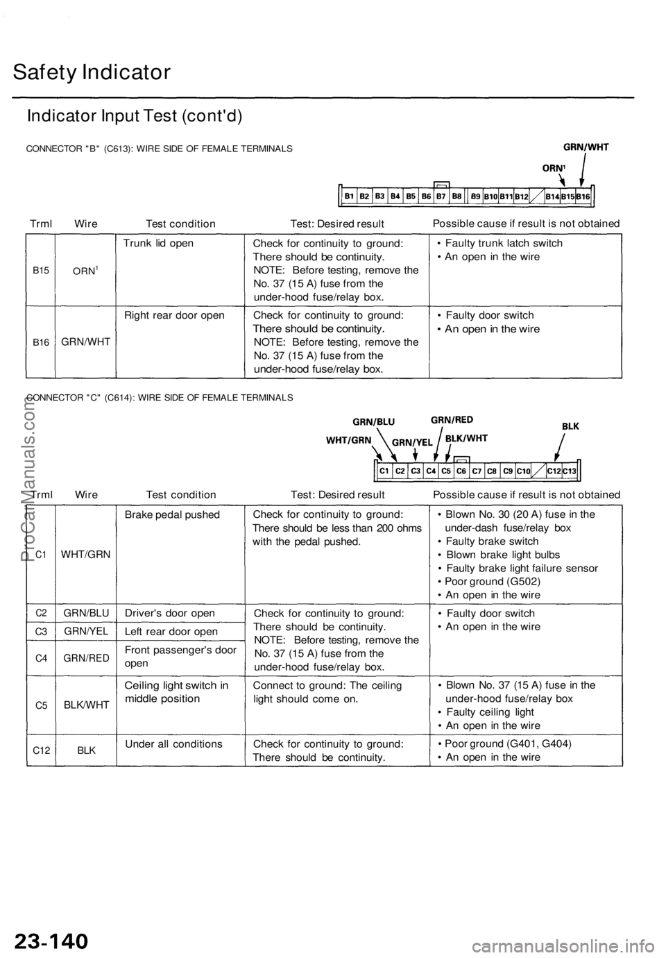
CONNECTOR "B" (C613): WIRE SIDE OF FEMALE TERMINALS
Trml Wire
Test condition
Test: Desired result
Possible cause if result is not obtained
B15
B16
ORN1
GRN/WHT
Trunk lid open
Right rear door open
Check for continuity to ground:
There should be continuity.
NOTE: Before testing, remove the
No. 37 (15 A) fuse from the
under-hood fuse/relay box.
Check for continuity to ground:
There should be continuity.
NOTE: Before testing, remove the
No. 37 (15 A) fuse from the
under-hood fuse/relay box.
• Faulty trunk latch switch
• An open in the wire
• Faulty door switch
• An open in the wire
CONNECTOR "C" (C614): WIRE SIDE OF FEMALE TERMINALS
Trml Wire
Test condition
Test: Desired result
Possible cause if result is not obtained
C1
C2
C3
C4
C5
C12
WHT/GRN
GRN/BLU
GRN/YEL
GRN/RED
BLK/WHT
BLK
Brake pedal pushed
Driver's door open
Left rear door open
Front passenger's door
open
Ceiling light switch in
middle position
Under all conditions
Check for continuity to ground:
There should be less than 200 ohms
with the pedal pushed.
Check for continuity to ground:
There should be continuity.
NOTE: Before testing, remove the
No. 37 (15 A) fuse from the
under-hood fuse/relay box.
Connect to ground: The ceiling
light should come on.
Check for continuity to ground:
There should be continuity.
• Blown No. 30 (20 A) fuse in the
under-dash fuse/relay box
• Faulty brake switch
• Blown brake light bulbs
• Faulty brake light failure sensor
• Poor ground (G502)
• An open in the wire
• Faulty door switch
• An open in the wire
• Blown No. 37 (15 A) fuse in the
under-hood fuse/relay box
• Faulty ceiling light
• An open in the wire
• Poor ground (G401, G404)
• An open in the wireProCarManuals.com
Page 1624 of 1771

Integrated Contro l Uni t
Inpu t Tes t
SRS component s ar e locate d i n thi s area . Revie w th e SR S componen t locations , precautions , an d procedure s i n th e SR S
( sectio n 24 ) befor e performin g repair s o r service .
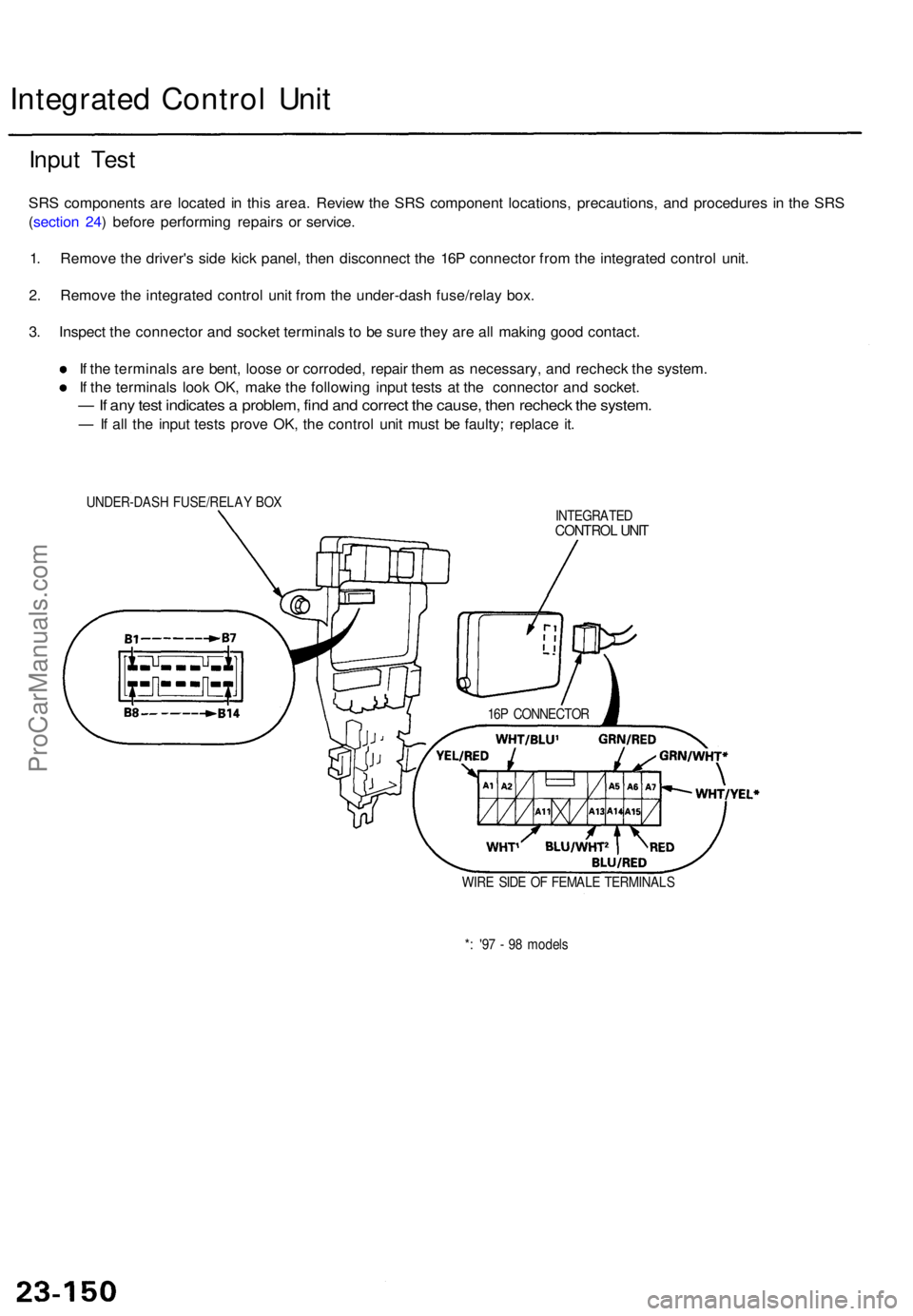
1 . Remov e th e driver' s sid e kic k panel , the n disconnec t th e 16 P connecto r fro m th e integrate d contro l unit .
2 . Remov e th e integrate d contro l uni t fro m th e under-das h fuse/rela y box .
3 . Inspec t th e connecto r an d socke t terminal s t o b e sur e the y ar e al l makin g goo d contact .
I f th e terminal s ar e bent , loos e o r corroded , repai r the m a s necessary , an d rechec k th e system .
I f th e terminal s loo k OK , mak e th e followin g inpu t test s a t th e connecto r an d socket .
— If an y tes t indicate s a problem , fin d an d correc t th e cause , the n rechec k th e system .
— If al l th e inpu t test s prov e OK , th e contro l uni t mus t b e faulty ; replac e it .
UNDER-DAS H FUSE/RELA Y BO X
INTEGRATED
CONTROL UNI T
16P CONNECTO R
WIR E SID E O F FEMAL E TERMINAL S
* : '9 7 - 9 8 model s
ProCarManuals.com
Page 1652 of 1771

Brake Light s an d Hig h Moun t Brak e Ligh t
Brake Switc h Tes t
1. I f on e o f th e brak e light s doe s no t g o on , chec k th e
bul b i n th e tailligh t o r th e hig h moun t brak e light .
2 . I f non e o f th e brak e light s g o on , chec k th e No . 3 0
(2 0 A ) fus e in th e under-hoo d fuse/rela y box .
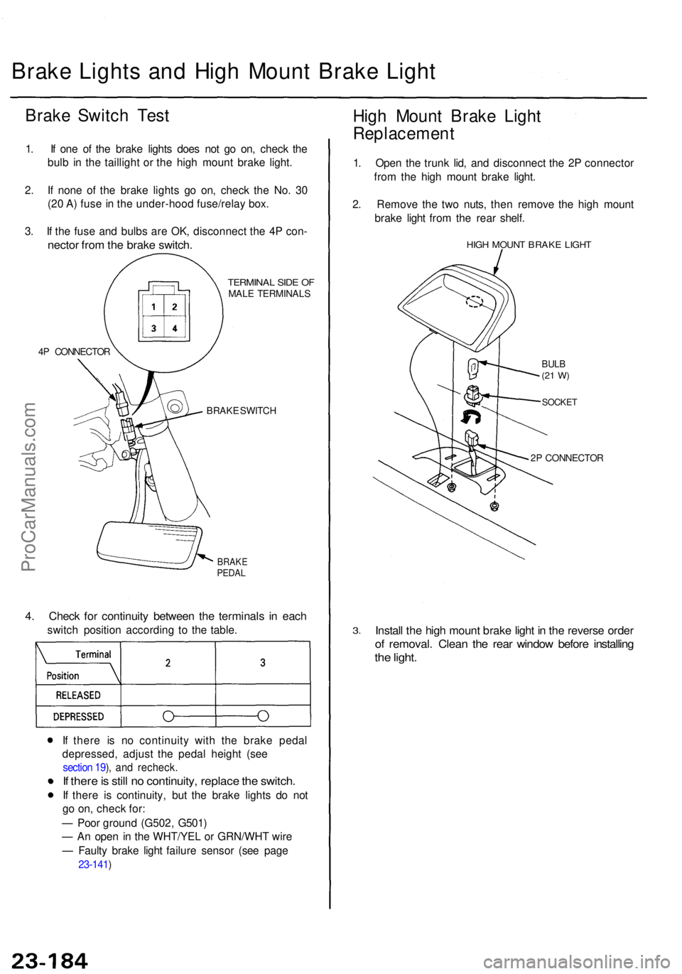
3 . I f th e fus e an d bulb s ar e OK , disconnec t th e 4 P con -
necto r fro m th e brak e switch .
4P CONNECTO R
TERMINAL SID E O FMAL E TERMINAL S
BRAK E SWITC H
BRAKEPEDAL
4. Chec k fo r continuit y betwee n th e terminal s i n eac h
switc h positio n accordin g t o th e table .
I f ther e i s n o continuit y wit h th e brak e peda l
depressed , adjus t th e peda l heigh t (se e
section 19 ), an d recheck .
If ther e is stil l n o continuity , replac e th e switch .
If ther e i s continuity , bu t th e brak e light s d o no t
g o on , chec k for :
— Poo r groun d (G502 , G501 )
— A n ope n i n th e WHT/YE L o r GRN/WH T wir e
— Fault y brak e ligh t failur e senso r (se e pag e
23-141 )
High Moun t Brak e Ligh t
Replacemen t
1. Ope n th e trun k lid , an d disconnec t th e 2 P connecto r
fro m th e hig h moun t brak e light .
2 . Remov e th e tw o nuts , the n remov e th e hig h moun t
brak e ligh t fro m th e rea r shelf .
HIGH MOUN T BRAK E LIGH T
BULB(21 W )
SOCKE T
2P CONNECTO R
3.Instal l th e hig h moun t brak e ligh t i n th e revers e orde r
of removal . Clea n th e rea r windo w befor e installin g
the light .
ProCarManuals.com