Page 215 of 1771
Idle Contro l Syste m
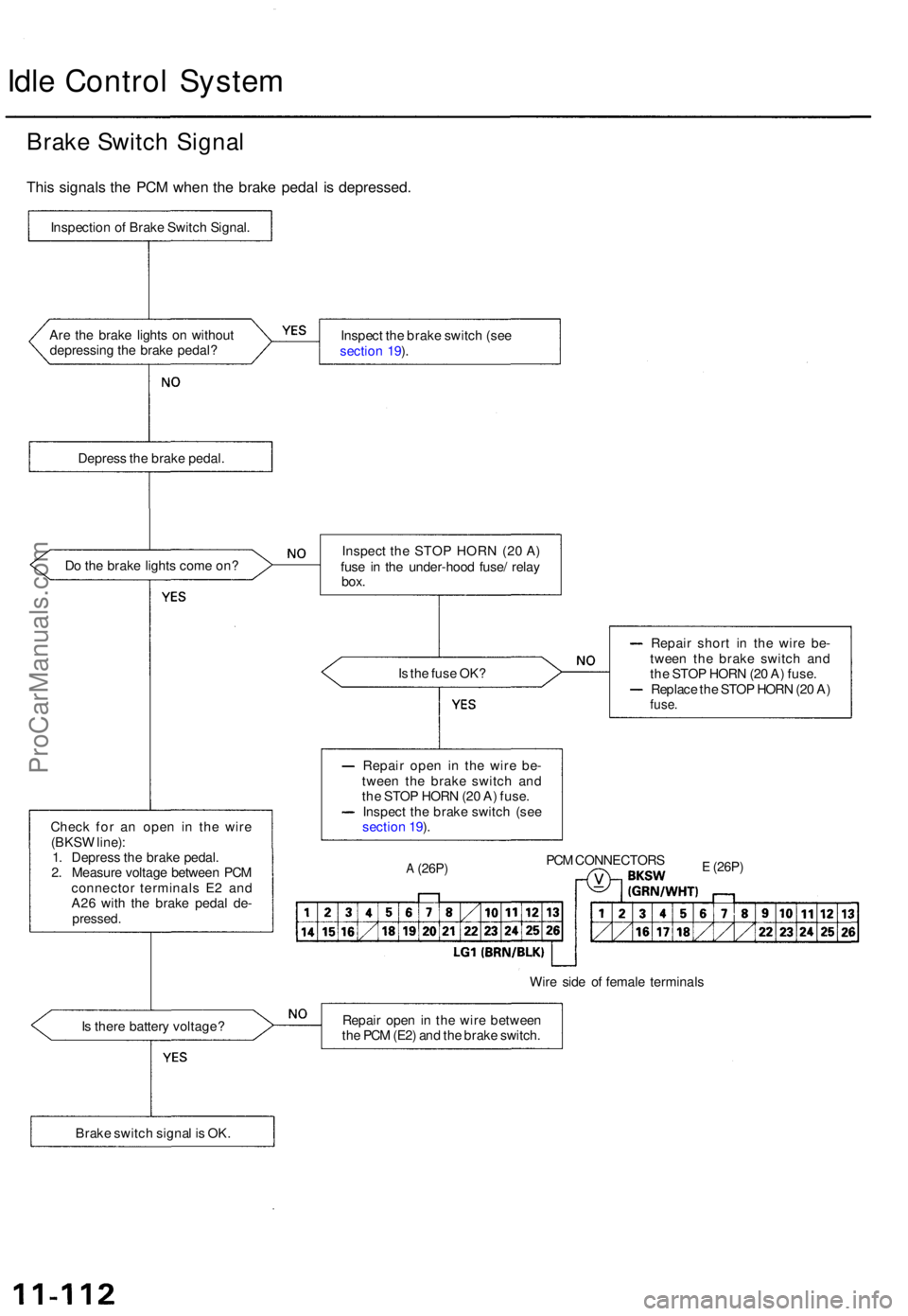
Brake Switc h Signa l
This signal s th e PC M whe n th e brak e peda l i s depressed .
Inspection o f Brak e Switc h Signal .
Ar e th e brak e light s o n withou t
depressin g th e brak e pedal ? Inspec
t th e brak e switc h (se e
sectio n 19 ).
Depres s th e brak e pedal .
D o th e brak e light s com e on ?
Is th e fus e OK ?
Chec k fo r a n ope n i n th e wir e
(BKS W line) :
1 . Depres s th e brak e pedal .
2 . Measur e voltag e betwee n PC M
connecto r terminal s E 2 an d
A2 6 wit h th e brak e peda l de -
pressed .
Repair shor t i n th e wire be-
twee n th e brak e switc h an d
th e STO P HOR N (2 0 A ) fuse .
Replac e th e STO P HOR N (2 0 A )
fuse .
Repai r ope n i n th e wir e be -
twee n th e brak e switc h an d
th e STO P HOR N (2 0 A ) fuse .
Inspec t th e brak e switc h (se e
sectio n 19 ).
A (26P )PCM CONNECTOR SE (26P)
Wire sid e o f femal e terminal s
I s ther e batter y voltage ? Repai
r ope n in th e wir e betwee n
th e PC M (E2 ) an d th e brak e switch .
Brak e switc h signa l i s OK . Inspec
t th e STO P HOR N (2 0 A )
fus e i n th e under-hoo d fuse / rela y
box.
ProCarManuals.com
Page 230 of 1771
Fuel Suppl y Syste m
Fuel Pressur e Regulato r (cont'd )
(From pag e 11-125 )
Chec k fo r a n ope n in th e wire :
Measur e voltag e betwee n th e
contro l bo x 4 P connecto r termi -
na l No . 4 an d bod y ground .
I s ther e batter y voltage ?
Chec k fo r a n ope n in th e wire :
1 . Tur n th e ignitio n switc h OFF .
2 . Reconnec t th e 4 P connecto r
t o th e contro l box .
3 . Star t th e engin e an d allo w it
to idle .4. Connec t PC M connecto r ter -
mina l A1 0 an d bod y groun d
with a jumpe r wire .
Is ther e manifol d vacuum ? CONTRO
L BO X
4 P CONNECTO R (C218 )
Repai r ope n i n wir e betwee n
No. 4 EC U (PCM ) (15 A ) o r (2 0 A )fus e in th e under-das h fuse/rela y
bo x an d th e 4 P connector . Wir
e sid e o f femal e terminal s
PC M CONNECTO R A (26P )
Wir e sid e o f femal e terminal s
Repai r ope n i n wir e betwee n
PC M (A10 ) an d th e 4 P connector .
Fue l Pressur e Regulato r Contro l
Solenoi d Valv e is OK .
JUMPE RWIRE
ProCarManuals.com
Page 236 of 1771
Fuel Suppl y Syste m
PGM-F I Mai n Rela y (cont'd )
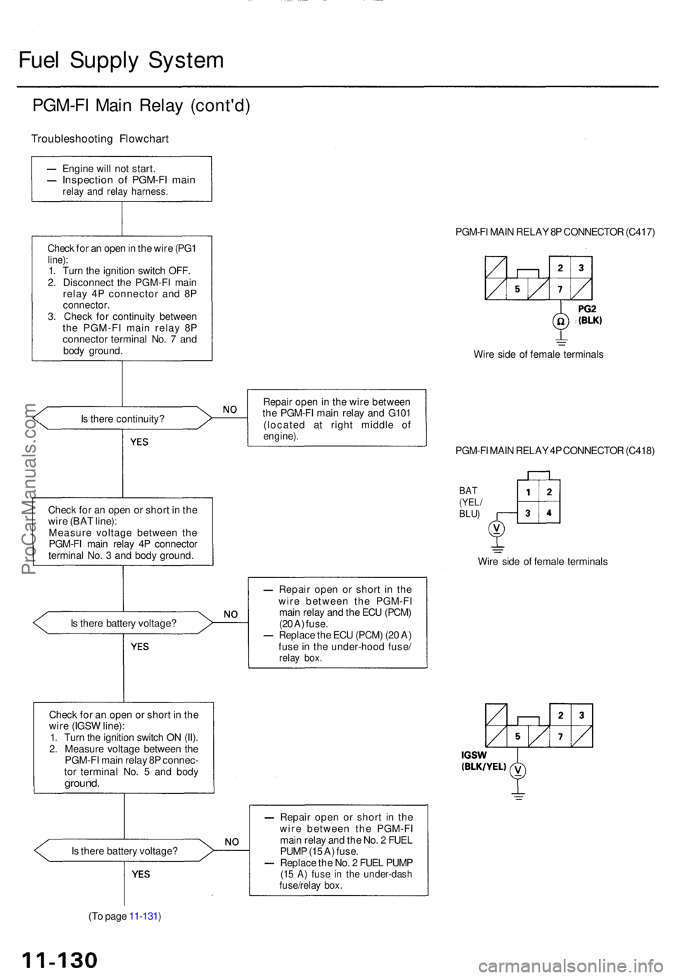
Troubleshootin g Flowchar t
Engine wil l no t start .Inspectio n o f PGM-F I mai nrelay an d rela y harness .
Check fo r a n ope n in th e wir e (PG 1line) :1. Tur n th e ignitio n switc h OFF .
2 . Disconnec t th e PGM-F I mai n
rela y 4 P connecto r an d 8 P
connector .3. Chec k fo r continuit y betwee n
th e PGM-F I mai n rela y 8 P
connecto r termina l No . 7 an d
bod y ground . PGM-F
I MAI N RELA Y 8P CONNECTO R (C417 )
Wir e sid e o f femal e terminal s
I s ther e continuity ? Repai
r ope n in th e wir e betwee n
th e PGM-F I mai n rela y an d G10 1
(locate d a t righ t middl e o f
engine) .
Check fo r a n ope n o r shor t i n th e
wir e (BA T line) :
Measur e voltag e betwee n th e
PGM-F I mai n rela y 4 P connecto r
termina l No . 3 an d bod y ground . PGM-F
I MAI N RELA Y 4P CONNECTO R (C418 )
BAT(YEL /BLU)
Wire sid e o f femal e terminal s
I s ther e batter y voltage ? Repai
r ope n o r shor t i n th e
wir e betwee n th e PGM-F I
mai n rela y an d th e EC U (PCM )
(2 0 A ) fuse .
Replac e th e EC U (PCM ) (2 0 A )
fus e in th e under-hoo d fuse /
relay box .
Chec k fo r a n ope n o r shor t i n th e
wir e (IGS W line) :
1 . Tur n th e ignitio n switc h O N (II) .
2 . Measur e voltag e betwee n th e
PGM-F I mai n rela y 8 P connec -
to r termina l No . 5 an d bod y
ground .
Is ther e batter y voltage ?
(T o pag e 11-131 ) Repai
r ope n o r shor t i n th e
wir e betwee n th e PGM-F I
mai n rela y an d th e No . 2 FUE L
PUM P (1 5 A ) fuse .
Replac e th e No . 2 FUE L PUM P
(15 A ) fus e i n th e under-das hfuse/relay box .
ProCarManuals.com
Page 237 of 1771
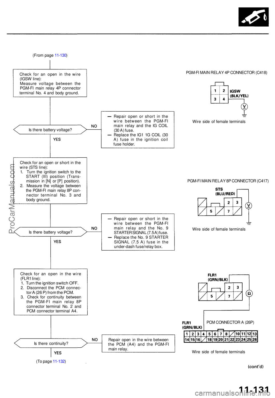
(From pag e 11-130 )
Chec k fo r a n ope n i n th e wir e
(IGS W line) :
Measur e voltag e betwee n th e
PGM-F I mai n rela y 4 P connecto r
termina l No . 4 an d bod y ground . PGM-F
I MAI N RELA Y 4 P CONNECTO R (C418 )
I s ther e batter y voltage ? Repai
r ope n o r shor t i n th e
wir e betwee n th e PGM-F I
mai n rela y an d th e I G COI L
(3 0 A ) fuse .
Replac e th e IG 1 1 G COI L (3 0
A ) fus e i n th e ignitio n coi l
fus e holder . Wir
e sid e o f femal e terminal s
Chec k fo r a n ope n o r shor t i n th e
wir e (ST S line) :
1 . Tur n th e ignitio n switc h t o th e
STAR T (III ) positio n (Trans -
missio n i n [N ] o r [P] position) .
2 . Measur e th e voltag e betwee n
th e PGM-F I mai n rela y 8 P con -
necto r termina l No . 3 an d
body ground .
PGM-FI MAI N RELA Y 8 P CONNECTO R (C417 )
I s ther e batter y voltage ? Repai
r ope n o r shor t i n th e
wir e betwee n th e PGM-F I
mai n rela y an d th e No . 9
STARTE R SIGNA L (7. 5 A ) fuse .
Replac e th e No . 9 STARTE R
SIGNA L (7. 5 A ) fus e i n th e
under-das h fuse/rela y box . Wir
e sid e o f femal e terminal s
Chec k fo r a n ope n i n th e wir e
(FLR 1 line) :
1. Tur n th e ignitio n switc h OFF .2. Disconnec t th e PC M connec -tor A (2 6 P ) fro m th e PCM .3. Chec k fo r continuit y betwee n
th e PGM-F I mai n rela y 8 P
connecto r termina l No . 2 an d
PC M connecto r termina l A4 .
I s ther e continuity ?
(T o pag e 11-132 ) Repai
r ope n in th e wir e betwee n
th e PC M (A4 ) an d th e PGM-F I
mai n relay . PC
M CONNECTO R A (26P )
Wir e sid e o f femal e terminal s
ProCarManuals.com
Page 239 of 1771
Intake Air System
System Description
The system supplies air for all engine needs. It consists of the intake air pipe, Air Cleaner (ACL), intake air duct, Throttle
Body (TB), Idle Air Control (IAC) Valve, fast idle thermo valve, and intake manifold.
A resonator in the intake air pipe provides additional silencing as air is drawn into the system.
IAB LOW
CONTROL
SOLENOID
VALVE
IAB HIGH
CONTROL SOLENOID VALVE
IAB LOW
CONTROL
DIAPHRAGM
VALVE
From PGM-FI
MAIN RELAY
From No. 4 ECU
(PCM)
(15 A)
FUSE
(in the under-dash
fuse/relay box)
VARIOUS
SENSORS
INTAKE
AIR
DUCT
FAST
IDLE
THERMO
VALVE
IDLE
ADJUSTING
SCREW
ENGINE
COOLANT
INTAKE
MANIFOLD
PCM
IAB
VACUUM
TANK
IAB
CHECK
VALVE
IAB HIGH
CONTROL
DIAPHRAGM
VALVEProCarManuals.com
Page 246 of 1771
Intake Ai r Syste m
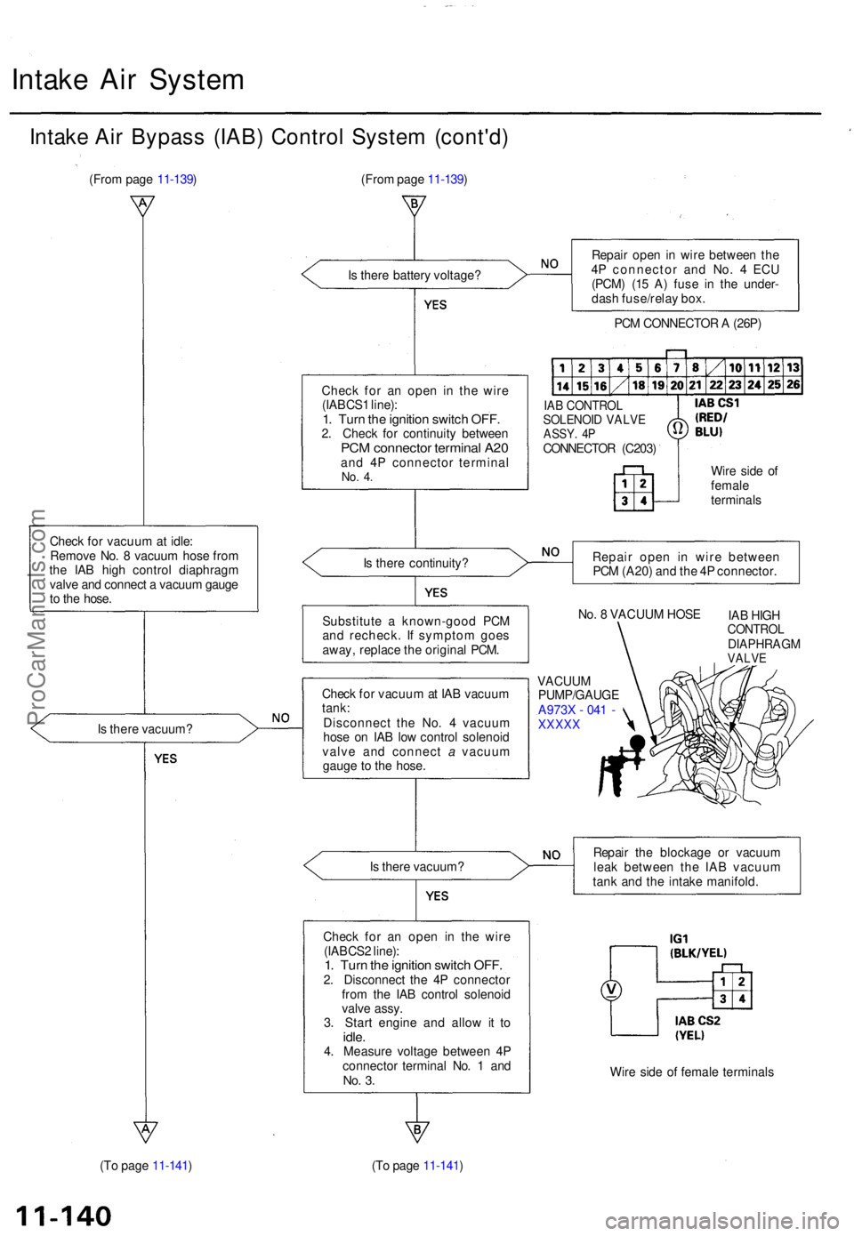
Intake Ai r Bypas s (IAB ) Contro l Syste m (cont'd )
(From pag e 11-139 )
Chec k fo r vacuu m at idle :
Remov e No . 8 vacuu m hos e fro m
th e IA B hig h contro l diaphrag m
valv e an d connec t a vacuu m gaug e
t o th e hose .
I s ther e vacuum ?
(T o pag e 11-141 ) (Fro
m pag e 11-139 )
I s ther e batter y voltage ?
Chec k fo r a n ope n i n th e wir e
(IABCS 1 line) :
1. Tur n th e ignitio n switc h OFF .2. Chec k fo r continuit y betwee nPCM connecto r termina l A2 0and 4 P connecto r termina lNo. 4 .
Is ther e continuity ?
Substitut e a known-goo d PC M
an d recheck . I f sympto m goe s
away , replac e th e origina l PCM .
Chec k fo r vacuu m at IA B vacuu m
tank :
Disconnec t th e No . 4 vacuu m
hos e o n IA B lo w contro l solenoi d
valv e an d connec t a vacuu m
gaug e t o th e hose .
I s ther e vacuum ?
Chec k fo r a n ope n i n th e wir e
(IABCS 2 line) :
1. Tur n th e ignitio n switc h OFF .2. Disconnec t th e 4 P connecto r
fro m th e IA B contro l solenoi d
valv e assy .
3 . Star t engin e an d allo w i t t o
idle .4. Measur e voltag e betwee n 4 P
connecto r termina l No . 1 an d
No. 3 .
(T o pag e 11-141 ) Repai
r ope n in wir e betwee n th e
4 P connecto r an d No . 4 EC U
(PCM ) (1 5 A ) fus e i n th e under -
das h fuse/rela y box .
PC M CONNECTO R A (26P )
IAB CONTRO LSOLENOID VALV EASSY. 4 PCONNECTO R (C203 )
Wire sid e o f
femal e
terminal s
Repai r ope n i n wir e betwee n
PC M (A20 ) an d th e 4 P connector .
No . 8 VACUU M HOS E
IAB HIG H
CONTRO LDIAPHRAG MVALVE
VACUU M
PUMP/GAUG E
A973 X - 04 1 -
XXXX X
Repair th e blockag e o r vacuu m
lea k betwee n th e IA B vacuu m
tan k an d th e intak e manifold .
Wir e sid e o f femal e terminal s
ProCarManuals.com
Page 247 of 1771
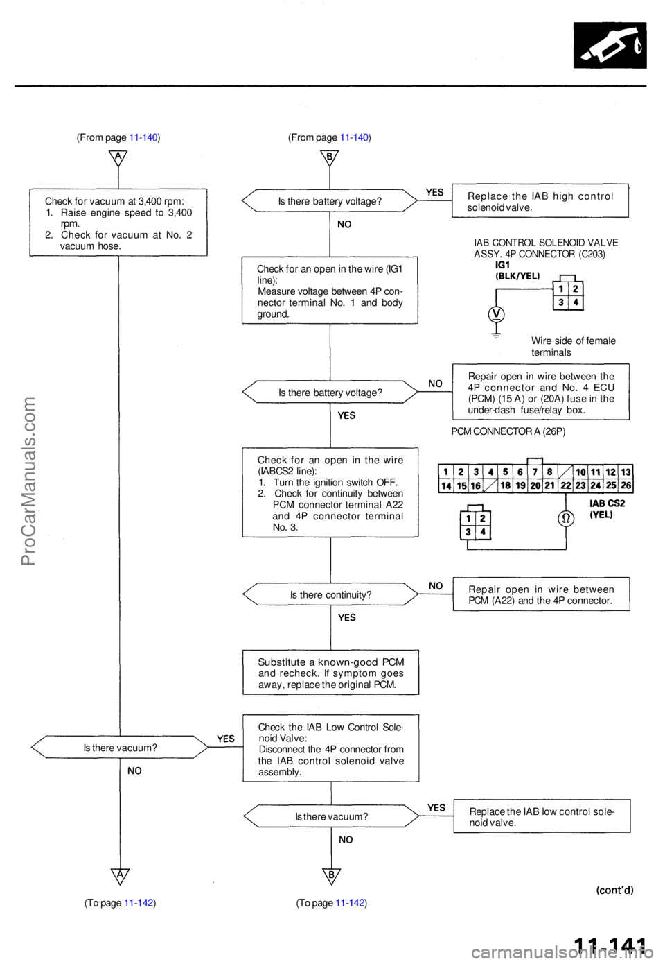
(From pag e 11-140 ) (From pag e 11-140 )
I s ther e batter y voltage ?
Chec k fo r a n ope n in th e wir e (IG 1
line) :Measur e voltag e betwee n 4 P con -
necto r termina l No . 1 an d bod y
ground .
I s ther e batter y voltage ?
Chec k fo r a n ope n i n th e wire
(IABCS 2 line) :
1 . Tur n th e ignitio n switc h OFF .
2 . Chec k fo r continuit y betwee n
PC M connecto r termina l A2 2
an d 4 P connecto r termina l
No. 3 .
Is ther e continuity ?
Chec k th e IA B Lo w Contro l Sole -
noi d Valve :
Disconnec t th e 4 P connecto r fro m
th e IA B contro l solenoi d valv e
assembly . Replac
e th e IA B hig h contro l
solenoi d valve .
IAB CONTRO L SOLENOI D VALV EASSY. 4 P CONNECTO R (C203 )
Wire sid e o f femal e
terminal s
Repai r ope n in wir e betwee n th e
4 P connecto r an d No . 4 EC U
(PCM ) (1 5 A ) o r (20A ) fus e in th e
under-das h fuse/rela y box .
PC M CONNECTO R A (26P )
Repai r ope n i n wir e betwee n
PC M (A22 ) an d th e 4 P connector .
I s ther e vacuum ? Replac
e th e IA B lo w contro l sole -
noi d valve .
(T o pag e 11-142 ) (To pag e 11-142 )
Substitut e a known-goo d PC Mand recheck . I f sympto m goe s
away , replac e th e origina l PCM .
I s ther e vacuum ?
Chec
k fo r vacuu m at 3,40 0 rpm :
1 . Rais e engin e spee d t o 3,40 0
rpm.2. Chec k fo r vacuu m a t No . 2
vacuu m hose .
ProCarManuals.com
Page 251 of 1771
Emission Control System
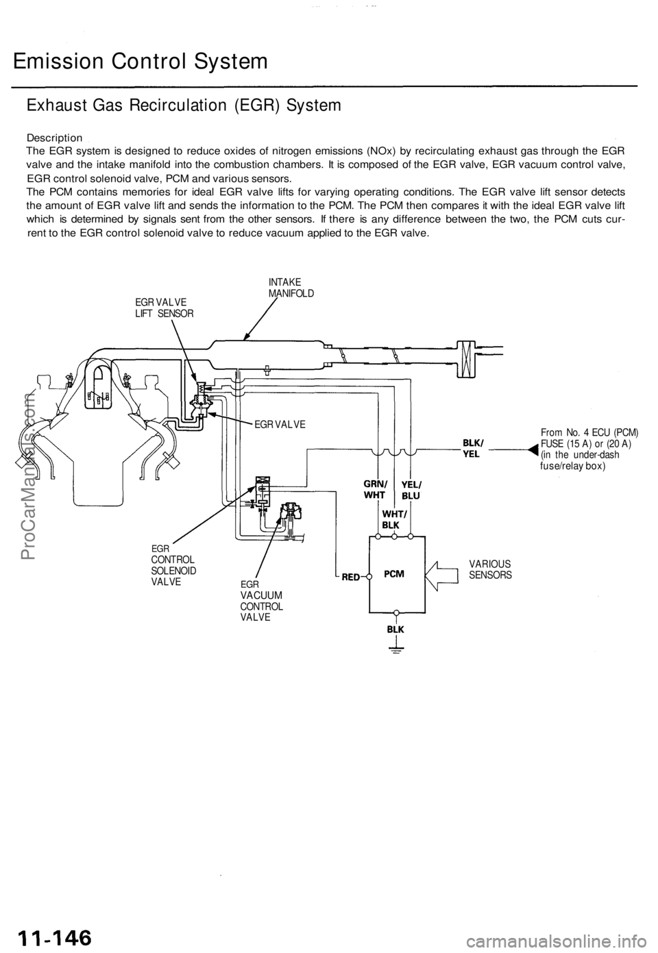
Exhaust Gas Recirculation (EGR) System
Description
The EGR system is designed to reduce oxides of nitrogen emissions (NOx) by recirculating exhaust gas through the EGR
valve and the intake manifold into the combustion chambers. It is composed of the EGR valve, EGR vacuum control valve,
EGR control solenoid valve, PCM and various sensors.
The PCM contains memories for ideal EGR valve lifts for varying operating conditions. The EGR valve lift sensor detects
the amount of EGR valve lift and sends the information to the PCM. The PCM then compares it with the ideal EGR valve lift
which is determined by signals sent from the other sensors. If there is any difference between the two, the PCM cuts cur-
rent to the EGR control solenoid valve to reduce vacuum applied to the EGR valve.
EGR VALVE
LIFT SENSOR
INTAKE
MANIFOLD
From No. 4 ECU (PCM)
FUSE (15 A) or (20 A)
(in the under-dash
fuse/relay box)
EGR
CONTROL
SOLENOID
VALVE
EGR
VACUUM
CONTROL
VALVE
VARIOUS
SENSORS
EGR VALVEProCarManuals.com