1995 ACURA TL engine
[x] Cancel search: enginePage 1264 of 1771
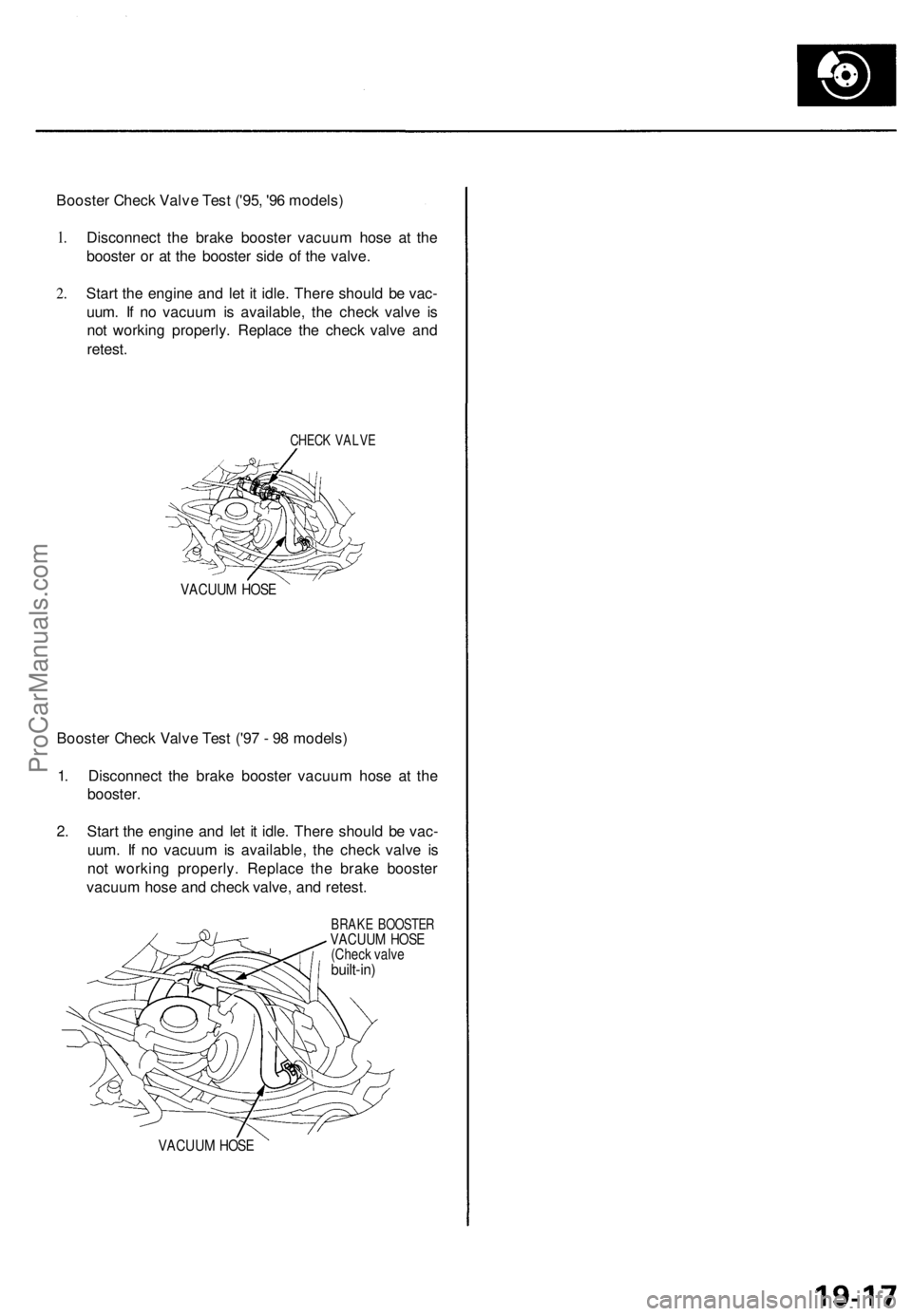
Booster Check Valve Test ('95, '96 models)
1.
2.
Disconnect the brake booster vacuum hose at the
booster or at the booster side of the valve.
Start the engine and let it idle. There should be vac-
uum. If no vacuum is available, the check valve is
not working properly. Replace the check valve and
retest.
CHECK VALVE
VACUUM HOSE
Booster Check Valve Test ('97 - 98 models)
1. Disconnect the brake booster vacuum hose at the
booster.
2. Start the engine and let it idle. There should be vac-
uum. If no vacuum is available, the check valve is
not working properly. Replace the brake booster
vacuum hose and check valve, and retest.
BRAKE BOOSTER
VACUUM HOSE
(Check valve
built-in)
VACUUM HOSEProCarManuals.com
Page 1291 of 1771
Pump motor control:
The ABS control unit monitors the brake fluid pressure in the accumulator by the pressure switch ON/OFF signals. The
ABS control unit turns the pump on when the pressure in the accumulator drops, and stops the pump when the pressure
rises to the specified value.
If the pressure does not reach the specified value after the motor has operated continuously for a specified period, the
ABS control unit stops the motor and activates the ABS indicator light.
Self-diagnosis function:
The self-diagnosis function, provided in the sub-function of the ABS control unit, monitors the main system functions by
constantly transmitting the data between the two Central Processing Units (CPUs). When an abnormality is detected, the
ABS control unit turns the ABS indicator light on and stops the ABS, although the basic brake system continues to operate
normally.
When the ABS control unit detects an abnormality with the ABS and turns the ABS indicator light on, the diagnostic trou-
ble code (DTC), which shows the problem part or unit, is recorded in the control unit. The DTC can be read by the blinking
frequency of the ABS indicator light.
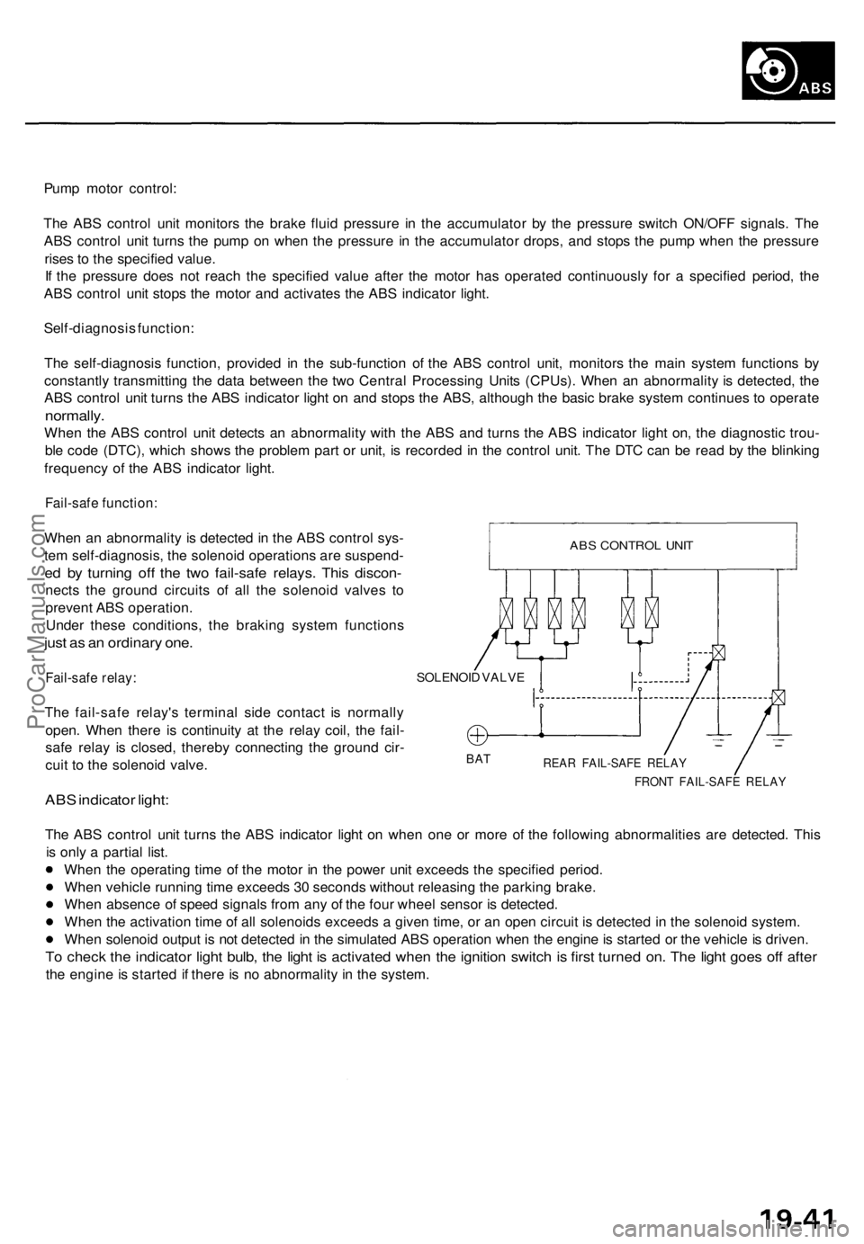
Fail-safe function:
When an abnormality is detected in the ABS control sys-
tem self-diagnosis, the solenoid operations are suspend-
ed by turning off the two fail-safe relays. This discon-
nects the ground circuits of all the solenoid valves to
prevent ABS operation.
Under these conditions, the braking system functions
just as an ordinary one.
Fail-safe relay:
The fail-safe relay's terminal side contact is normally
open. When there is continuity at the relay coil, the fail-
safe relay is closed, thereby connecting the ground cir-
cuit to the solenoid valve.
ABS indicator light:
SOLENOID VALVE
BAT
REAR FAIL-SAFE RELAY
FRONT FAIL-SAFE RELAY
The ABS control unit turns the ABS indicator light on when one or more of the following abnormalities are detected. This
is only a partial list.
When the operating time of the motor in the power unit exceeds the specified period.
When vehicle running time exceeds 30 seconds without releasing the parking brake.
When absence of speed signals from any of the four wheel sensor is detected.
When the activation time of all solenoids exceeds a given time, or an open circuit is detected in the solenoid system.
When solenoid output is not detected in the simulated ABS operation when the engine is started or the vehicle is driven.
To check the indicator light bulb, the light is activated when the ignition switch is first turned on. The light goes off after
the engine is started if there is no abnormality in the system.
ABS CONTROL UNITProCarManuals.com
Page 1299 of 1771
Troubleshooting Precautions
ABS Indicator Light:
The ABS indicator light comes on for three seconds and then goes off when the control unit detects no problem during the
initial diagnosis right after the engine starts. However, the ABS indicator light can stay on for up to 40 seconds when the
control unit starts to check for pump overrun, etc. during the initial diagnosis. The ABS indicator light comes on, and the
ABS control unit memorizes the diagnostic trouble code (DTC) under certain conditions.
The parking brake is applied for more than 30 seconds while the vehicle is being driven. (DTC 2-1)
The transmission downshifted excessively. (DTC 4-1, 4-2)
The vehicle loses traction, and the front wheels spin for more than one minute when starting from a stuck condition on
a muddy, snowy, or sandy road. (DTC 4-8)
Tire adhesion is lost due to excessive cornering speed. (DTC 5, 5-4, 5-8)
The vehicle is driven on an extremely rough road. (DTC 8-1)
The vehicle is interfered by strong radio waves (noise), for example, illegal radio, etc. (DTC 8-2)
NOTE: If there is any trouble in the system, the ABS indicator light comes on during driving.
Diagnostic Trouble Code (DTC):
When the control unit detects a problem and the ABS indicator light comes on, the control unit memorizes the DTC.
The control unit has three memory registers. When a problem occurs, the control unit stores the DTC in the first memory
register. If another problem occurs, or the same problem occurs again, the control unit moves the first DTC to the next
memory register, and stores the second DTC in the first register. If there's a third problem occurrence, the two existing
DTCs are moved up one register, and the third DTC is stored in the first register. If problems continue to occur, the oldest
problem is moved out of the last register and lost, and the most recent problem is stored in the first register. When the
same problem occurs three times, the same DTC is stored in all memory registers. (Refer to the Symptom-to-System
Chart for diagnostic period.)
The most recent DTC is indicated first, and the oldest DTC is indicated last.
The DTCs are erased from the control unit when the ABS control unit +B2 power supply or connector is disconnected.
The control unit's memory can be erased by disconnecting the ABS B2 fuse for more than three seconds.
Self-diagnosis:
There are three self-diagnosises described below.
Initial diagnosis: Performed right after the engine starts until the ABS indicator light goes off.
Regular diagnosis: Continuously performed (under some conditions) after the ABS indicator light goes off until the
engine stops.
Individual part/system diagnosis: Diagnosis about a specific part/system under its operating conditions.
The CPU (central processing unit) controls the following when it detects a problem during self-diagnosis:
Turns the ABS indicator light ON.
Turns the front and rear fail-safe relays off.
Stops the ABS control.
Stops the ABS pump. (The pump may work under some conditions.)
After the DTC is stored in the control unit, the CPU stops self-diagnosis.ProCarManuals.com
Page 1300 of 1771
Kickback and Pump Operation:
When the engine is started, the ABS control unit begins the initial diagnosis and operates the solenoid valve one time.
The kickback may be felt when the brake pedal is depressed.
When the ABS control unit detects the pressure switch OFF signal during the initial diagnosis, it operates the pump
motor, and performs the pump motor over-run diagnosis and pump motor diagnosis. Therefore, there are two cases
where the pump motor operates or does not operate after the engine is started.
Normally, after the initial diagnosis, the pump motor operates based on the pressure switch signal, regardless of the
vehicle speed.
Troubleshooting:
When two or three DTCs are stored in the control unit, perform troubleshooting for the DTC that appears first.
When a customer's reported problem cannot be verified on the car, ask the customer about the conditions when the
ABS indicator light came ON, and test-drive the car under those conditions, if possible. When the ABS indicator light
does not come ON during the test, check for loose terminals and check by shaking the harnesses and connectors while
following the flowchart.
The connector terminal numbers are viewed from the wire side for the female terminals, and from the terminal side for
the male terminals.
After the repair is completed, test-drive the car and check that the ABS indicator light does not come ON again during
the test. (Refer to the Symptom-to-System Chart for diagnostic period.)ProCarManuals.com
Page 1301 of 1771
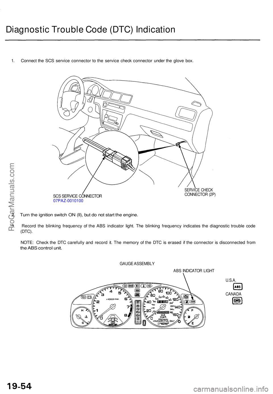
Diagnostic Troubl e Cod e (DTC ) Indicatio n
1. Connec t th e SC S servic e connecto r t o th e servic e chec k connecto r unde r th e glov e box .
SCS SERVIC E CONNECTO R07PAZ-001010 0
SERVICE CHEC KCONNECTO R (2P )
2. Tur n th e ignitio n switc h O N (II) , bu t d o no t star t th e engine .
3. Recor d th e blinkin g frequenc y o f th e AB S indicator light. Th e blinkin g frequenc y indicate s th e diagnosti c troubl e cod e
(DTC) .
NOTE : Chec k th e DT C carefull y an d recor d it . Th e memor y o f th e DT C is erase d i f th e connecto r i s disconnecte d fro m
the AB S contro l unit .
GAUG E ASSEMBL Y
ABS INDICATO R LIGH T
U.S.A.
CANAD A
ProCarManuals.com
Page 1302 of 1771
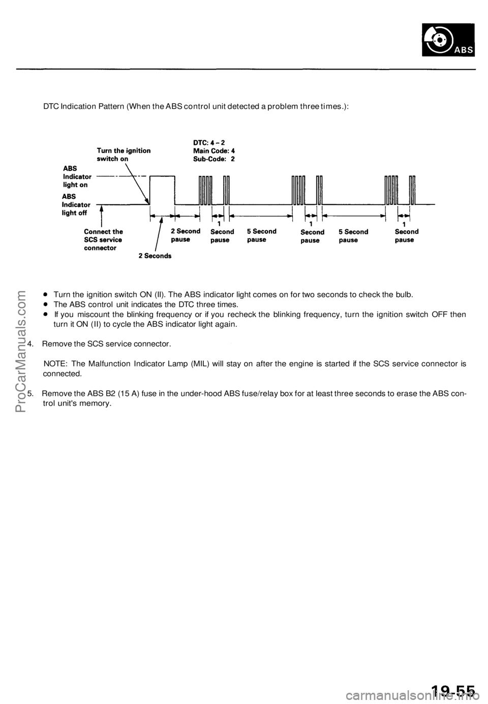
DTC Indication Pattern (When the ABS control unit detected a problem three times.):
Turn the ignition switch ON (II). The ABS indicator light comes on for two seconds to check the bulb.
The ABS control unit indicates the DTC three times.
If you miscount the blinking frequency or if you recheck the blinking frequency, turn the ignition switch OFF then
turn it ON (II) to cycle the ABS indicator light again.
4. Remove the SCS service connector.
NOTE: The Malfunction Indicator Lamp (MIL) will stay on after the engine is started if the SCS service connector is
connected.
5. Remove the ABS B2 (15 A) fuse in the under-hood ABS fuse/relay box for at least three seconds to erase the ABS con-
trol unit's memory.ProCarManuals.com
Page 1307 of 1771
ABS Functio n Tes t
Modulato r Functio n Chec k
NOTE : Thi s inspectio n determine s whethe r th e basi c
brake syste m continue s t o operat e normall y whe n th e
modulato r uni t flui d pressur e i s low .
CAUTION :
Thi s inspectio n i s mad e b y relievin g th e high-pres -
sur e flui d i n th e modulato r uni t an d checkin g fo r
brak e operation . Afte r inspection , b e sur e t o ad d
fres h brak e flui d t o th e specifie d leve l o f th e reser -
voir , an d star t th e engin e t o restor e th e AB S t o it s
norma l operatin g condition .
D o no t spil l brak e flui d o n th e car ; i t ma y damag e th e
paint ; i f brak e flui d doe s contac t th e paint , was h i t
of f immediatel y wit h water .
D o no t reus e th e draine d brak e fluid .
D o no t loose n th e relie f plu g o n th e accumulator .
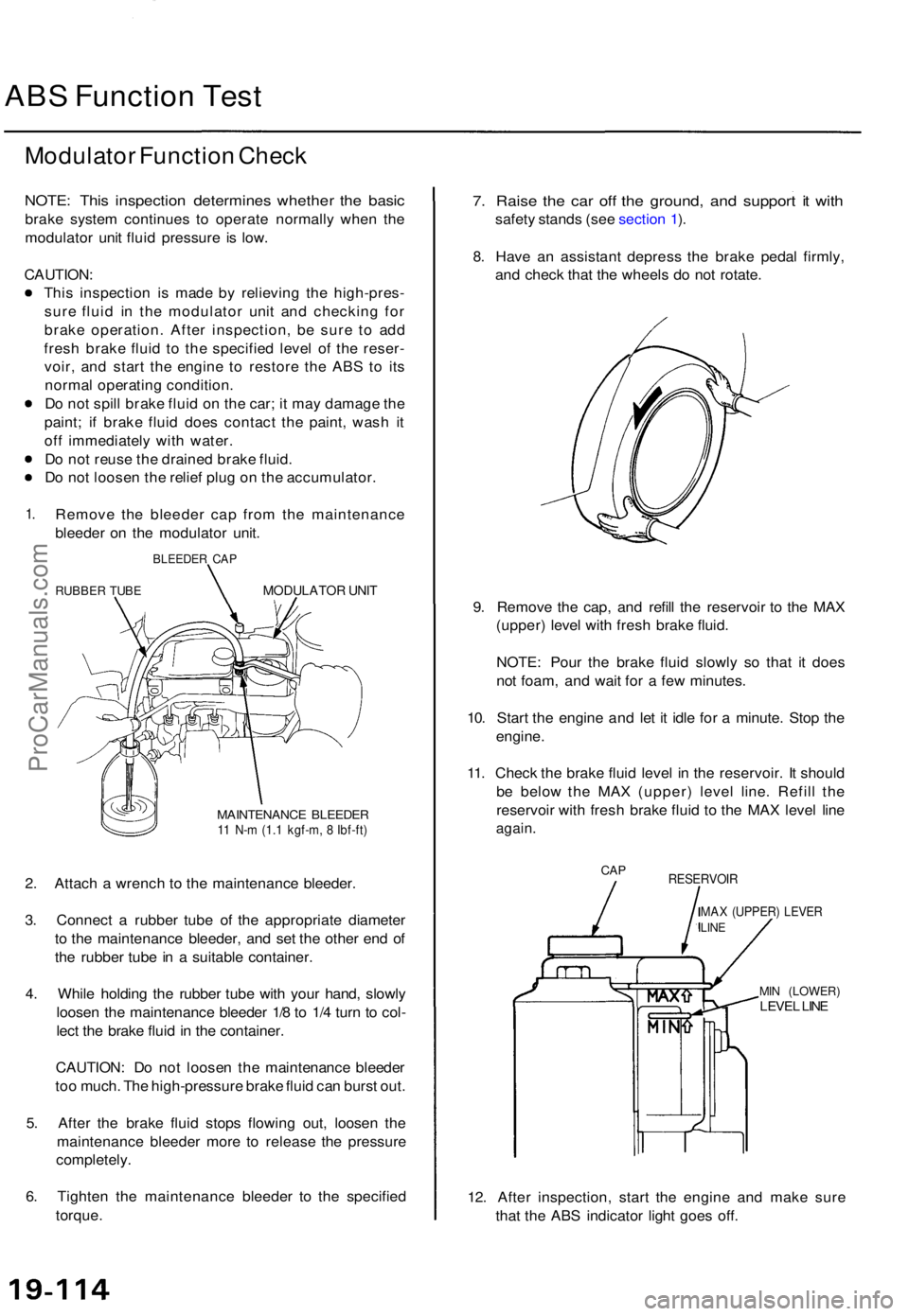
1.Remov e th e bleede r ca p fro m th e maintenanc e
bleede r o n th e modulato r unit .
BLEEDE R CA P
RUBBE R TUB EMODULATO R UNI T
MAINTENANC E BLEEDE R11 N- m (1. 1 kgf-m , 8 Ibf-ft )
2. Attac h a wrenc h t o th e maintenanc e bleeder .
3 . Connec t a rubbe r tub e o f th e appropriat e diamete r
t o th e maintenanc e bleeder , an d se t th e othe r en d o f
th e rubbe r tub e in a suitabl e container .
4 . Whil e holdin g th e rubbe r tub e wit h you r hand , slowl y
loose n th e maintenanc e bleede r 1/ 8 to 1/ 4 tur n t o col -
lec t th e brak e flui d in th e container .
CAUTION : D o no t loose n th e maintenanc e bleede r
to o much . Th e high-pressur e brak e flui d ca n burs t out .
5 . Afte r th e brak e flui d stop s flowin g out , loose n th e
maintenanc e bleede r mor e t o releas e th e pressur e
completely .
6 . Tighte n th e maintenanc e bleede r t o th e specifie d
torque .
7. Rais e th e ca r of f th e ground , an d suppor t i t wit h
safet y stand s (se e sectio n 1 ).
8 .Hav e a n assistan t depres s th e brak e peda l firmly ,
an d chec k tha t th e wheel s d o no t rotate .
9 . Remov e th e cap , an d refil l th e reservoi r t o th e MA X
(upper ) leve l wit h fres h brak e fluid .
NOTE : Pou r th e brak e flui d slowl y s o tha t i t doe s
no t foam , an d wai t fo r a fe w minutes .
10 . Star t th e engin e an d le t i t idl e fo r a minute . Sto p th e
engine .
11 . Chec k th e brak e flui d leve l i n th e reservoir . I t shoul d
b e belo w th e MA X (upper ) leve l line . Refil l th e
reservoi r wit h fres h brak e flui d t o th e MA X leve l lin e
again .
CAPRESERVOI R
MAX (UPPER ) LEVE RLINE
MIN (LOWER )LEVEL LIN E
12. Afte r inspection , star t th e engin e an d mak e sur e
tha t th e AB S indicato r ligh t goe s off .
ProCarManuals.com
Page 1310 of 1771
Modulator Uni t
Brak e Flui d Replacement/Bleedin g (cont'd )
6. Star t th e engin e an d le t i t idl e fo r a minute . Sto p th e
engine .
7 . Chec k th e brak e flui d leve l i n th e reservoir . I t shoul d
b e belo w th e MA X (upper ) leve l line .
8 . Repea t th e step s 4 throug h 7 to drai n th e res t o f th e
brak e flui d fro m th e modulato r unit .
NOTE : Th e modulato r ha s a capacit y o f approximatel y
150 ( 5 fl-oz , 5. 3 Imp-oz) . Approximatel y 3 5 - 4 5
(1 1/6- 1 1/ 2 fl-oz , 1.2-1. 6 Imp-oz ) o f th e flui d i s
draine d a t eac h try .
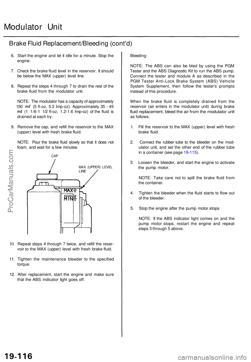
9 . Remov e th e cap , an d refil l th e reservoi r t o th e MA X
(upper ) leve l wit h fres h brak e fluid .
NOTE : Pou r th e brak e flui d slowl y s o tha t i t doe s no t
foam , an d wai t fo r a fe w minutes .
10.
CA P
MA X (UPPER ) LEVE LLINE
Repea t step s 4 throug h 7 twice , an d refil l th e reser -
voi r t o th e MA X (upper ) leve l wit h fres h brak e fluid .
11 . Tighten the maintenanc e bleede r t o th e specifie d
torque .
12 . Afte r replacement , star t th e engin e an d mak e sur e
tha t th e AB S indicator light goe s off .
Bleeding :
NOTE: Th e AB S ca n als o b e ble d b y usin g th e PG M
Teste r an d th e AB S Diagnosti c Ki t t o ru n th e AB S pump .
Connec t th e teste r an d modul e A as describe d i n th e
PG M Teste r Anti-Loc k Brak e Syste m (ABS ) Vehicl e
Syste m Supplement , the n follo w th e tester' s prompt s
instea d o f thi s procedure .
Whe n th e brak e flui d i s completel y draine d fro m th e
reservoi r (ai r enter s i n th e modulato r unit ) durin g brak e
fluid replacement , blee d th e ai r fro m th e modulato r uni t
as follows .
1 . Fil l th e reservoi r t o th e MA X (upper ) leve l wit h fres h
brak e fluid .
2 . Connec t th e rubbe r tub e t o th e bleede r o n th e mod -
ulato r unit , an d se t th e othe r en d o f th e rubbe r tub e
i n a containe r (se e page 19-115 ).
3 . Loose n th e bleeder , an d star t th e engin e t o activat e
th e pum p motor .
NOTE : Tak e car e no t t o spil l th e brak e flui d fro m
th e container .
4 . Tighte n th e bleede r whe n th e flui d start s t o flo w ou t
o f th e bleeder .
5 . Sto p th e engin e afte r th e pum p moto r stop s
NOTE : I f th e AB S indicato r ligh t come s o n an d th e
pum p moto r stops , restar t th e engin e an d repea t
step s 3 throug h 5 above .
ProCarManuals.com