Page 1010 of 1771
25. Remove the transmission mid mount nuts.
26. Place a jack under the transmission and raise the
transmission just enough to take weight off of the
mounts, then remove the mid mounts and mid mount
spacer as shown.
TRANSMISSION
TRANSMISSION
MID MOUNT
NUT
MID MOUNT
SPACER
MID MOUNT
MID MOUNTS
OFFSET WRENCH
(Commercially available)
27. Remove the transmission housing mounting bolts.
28. Remove the torque converter cover mounting bolt on
the torque converter housing side.
NOTE: Do not remove the torque converter cover
mounting bolt on the differential carrier side and the
torque converter cover.
TRANSMISSION
HOUSING
MOUNTING
BOLT
DOWEL PIN
TORQUE CONVERTER
COVER
Do not remove.
Do not remove
this bolt.
TRANSMISSION HOUSING
MOUNTING BOLT
TORQUE CONVERTER COVER
MOUNTING BOLT
Remove this bolt.
29. Pull the transmission away from the engine until it
clears the dowel pins, then lower it on the transmis-
sion jack.ProCarManuals.com
Page 1079 of 1771
Transmission
Installation
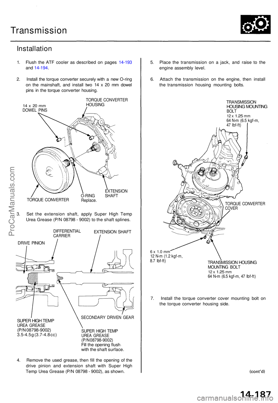
1. Flus h th e AT F coole r a s describe d o n page s 14-19 3
an d 14-194 .
2 . Instal l th e torqu e converte r securel y wit h a ne w O-rin g
o n th e mainshaft , an d instal l tw o 1 4 x 2 0 m m dowe l
pin s i n th e torqu e converte r housing .
14 x 20 m mDOWE L PIN S
TORQU E CONVERTE RHOUSING
TORQUE CONVERTE RO-RINGReplace .
EXTENSIO NSHAFT
3. Se t th e extensio n shaft , appl y Supe r Hig h Tem p
Ure a Greas e (P/ N 0879 8 - 9002 ) t o th e shaf t splines .
DIFFERENTIA LCARRIEREXTENSIO N SHAF T
DRIVE PINIO N
5. Plac e th e transmissio n o n a jack , an d rais e t o th e
engin e assembl y level .
6 . Attac h th e transmissio n o n th e engine , the n instal l
th e transmissio n housin g mountin g bolts .
TRANSMISSIO NHOUSING MOUNTIN GBOLT12 x 1.2 5 mm64 N- m (6. 5 kgf-m ,47 Ibf-ft )
TORQU E CONVERTE RCOVER
6 x 1. 0 m m12 N- m (1. 2 kgf-m ,8.7 Ibf-ft )TRANSMISSIO N HOUSIN GMOUNTIN G BOL T12 x 1.2 5 mm64 N- m (6. 5 kgf-m , 4 7 Ibf-ft )
7. Instal l th e torqu e converte r cove r mountin g bol t o n
th e torqu e converte r housin g side .
SECONDAR Y DRIVE N GEA RSUPER HIG H TEM PUREA GREAS E(P/N 08798-9002 )3.5-4.5 g (3.7-4. 8 cc )SUPE R HIG H TEM PUREA GREAS E(P/N 08798-9002 )Fill th e openin g flus h
wit h th e shaf t surface .
4 . Remov e th e use d grease , the n fill the openin g o f th e
driv e pinio n an d extensio n shaf t wit h Supe r Hig h
Tem p Ure a Greas e (P/ N 0879 8 - 9002) , a s shown .
ProCarManuals.com
Page 1084 of 1771
Transmission
Installation (cont'd )
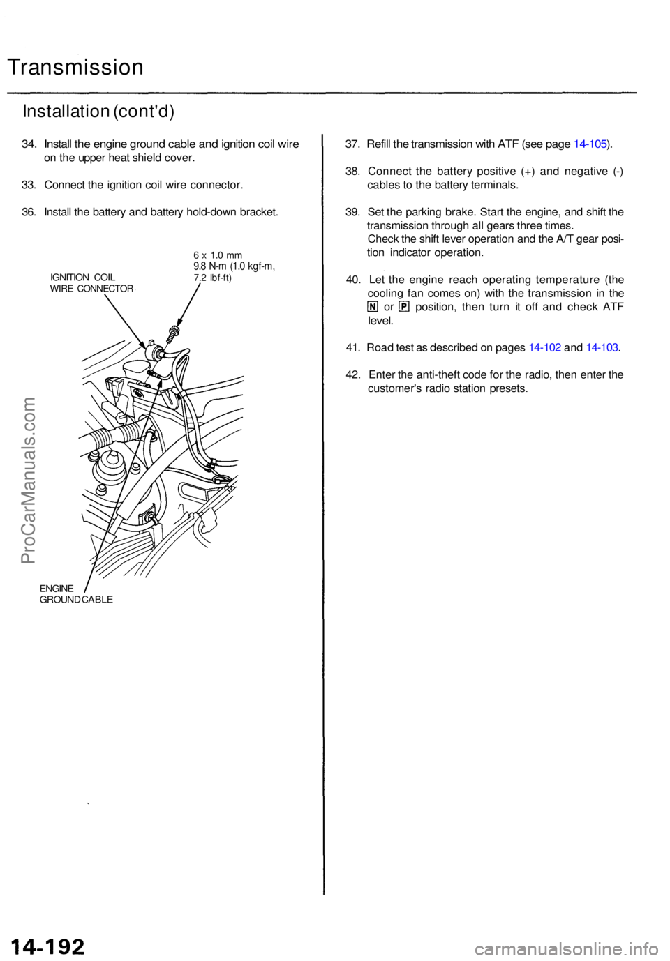
34. Instal l th e engin e groun d cabl e an d ignitio n coi l wir e
on th e uppe r hea t shiel d cover .
33 . Connec t th e ignitio n coi l wir e connector .
36 . Instal l th e batter y an d batter y hold-dow n bracket .
IGNITION COI LWIRE CONNECTO R
6 x 1. 0 m m9.8 N- m (1. 0 kgf-m ,7.2 Ibf-ft )
ENGIN EGROUN D CABL E
37. Refil l th e transmissio n wit h AT F (se e pag e 14-105 ).
38 . Connec t th e batter y positiv e (+ ) an d negativ e (- )
cable s t o th e batter y terminals .
39 . Se t th e parkin g brake . Star t th e engine , an d shif t th e
transmissio n throug h al l gear s thre e times .
Chec k th e shif t leve r operatio n an d th e A/ T gea r posi -
tio n indicato r operation .
40 . Le t th e engin e reac h operatin g temperatur e (th e
coolin g fa n come s on ) wit h th e transmissio n i n th e
or position , the n tur n i t of f an d chec k AT F
level .
41. Roa d tes t a s describe d o n page s 14-10 2 an d 14-103 .
42 . Ente r th e anti-thef t cod e fo r th e radio , the n ente r th e
customer' s radi o statio n presets .
ProCarManuals.com
Page 1090 of 1771
Shift Leve r
Link Adjustmen t
Make sur e lifts , jack s an d safet y stand s ar e place d
properl y (se e sectio n 1 ).
Appl y parkin g brake , an d bloc k rea r wheel s s o vehi -
cl e wil l no t rol l of f stand s an d fal l o n yo u whil e work -
in g unde r it .
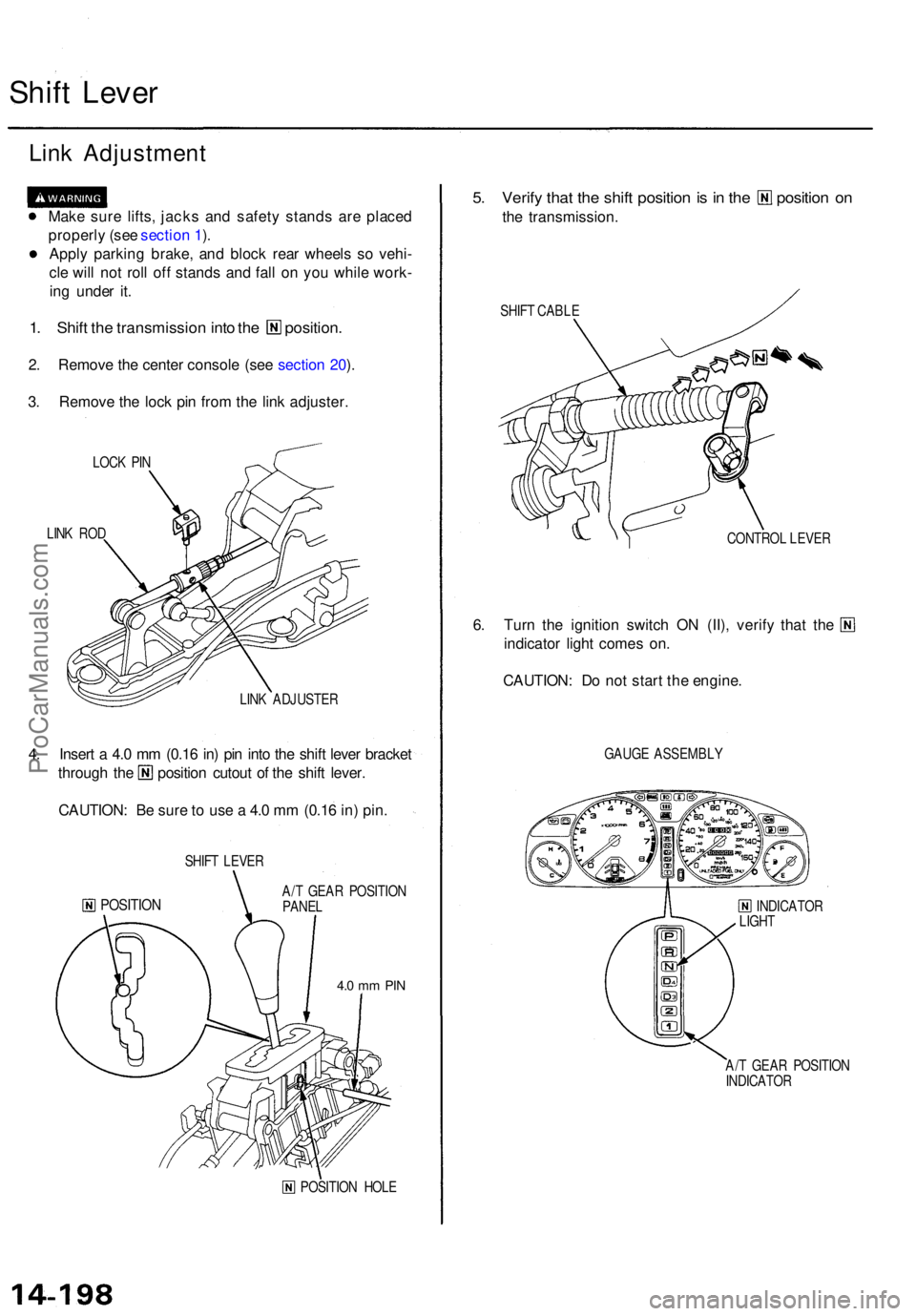
1. Shif t th e transmissio n int o th e position .
2. Remov e th e cente r consol e (se e sectio n 20 ).
3 . Remov e th e loc k pi n fro m th e lin k adjuster .
LOCK PI N
LIN K RO D
LINK ADJUSTE R
4. Inser t a 4. 0 m m (0.1 6 in ) pi n int o th e shif t leve r bracke t
through th e positio n cutou t o f th e shif t lever .
CAUTION : B e sur e to us e a 4. 0 m m (0.1 6 in ) pin .
SHIF T LEVE R
POSITIO NA/T GEA R POSITIO N
PANE L
4.0 m m PI N
POSITIO N HOL E
5. Verif y tha t th e shif t positio n is i n th e positio n o n
the transmission .
SHIFT CABL E
CONTROL LEVE R
6. Tur n th e ignitio n switc h O N (II) , verif y tha t th e
indicator light come s on .
CAUTION : D o no t star t th e engine .
GAUGE ASSEMBL Y
INDICATO R
LIGH T
A/ T GEA R POSITIO N
INDICATO R
ProCarManuals.com
Page 1091 of 1771
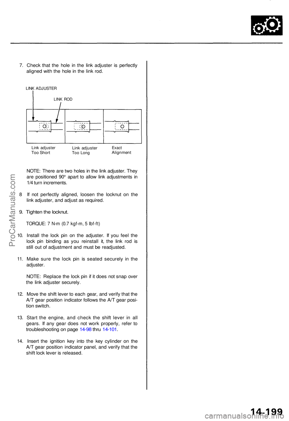
7. Chec k tha t th e hol e i n th e lin k adjuste r i s perfectl y
aligne d wit h th e hol e in th e lin k rod .
LINK ADJUSTE R
LINK RO D
Link adjuste rToo Shor tLink adjuste rToo Lon gExac tAlignmen t
NOTE: Ther e ar e tw o hole s in th e lin k adjuster . The y
ar e positione d 90 ° apar t t o allo w lin k adjustment s i n
1/ 4 tur n increments .
8 I f no t perfectl y aligned , loose n th e locknu t o n th e
lin k adjuster , an d adjus t a s required .
9. Tighte n th e locknut .
TORQUE : 7 N- m (0. 7 kgf-m , 5 Ibf-ft )
10. Instal l th e loc k pi n o n th e adjuster . I f yo u fee l th e
loc k pi n bindin g a s yo u reinstal l it , th e lin k ro d i s
stil l ou t o f adjustmen t an d mus t b e readjusted .
11 . Mak e sur e th e loc k pi n i s seate d securel y i n th e
adjuster .
NOTE : Replac e th e loc k pi n if i t doe s no t sna p ove r
th e lin k adjuste r securely .
12 . Mov e th e shif t leve r t o eac h gear , an d verif y tha t th e
A/ T gea r positio n indicato r follow s th e A/ T gea r posi -
tion switch .
13. Star t th e engine , an d chec k th e shif t leve r i n al l
gears . I f an y gea r doe s no t wor k properly , refe r t o
troubleshootin g o n pag e 14-9 8 thr u 14-101 .
14. Inser t th e ignitio n ke y int o th e ke y cylinde r o n th e
A/ T gea r positio n indicato r panel , an d verif y tha t th e
shif t loc k leve r i s released .
ProCarManuals.com
Page 1096 of 1771
Differential Assembl y
Removal
Make sur e jack s an d safet y stand s ar e place d properly ,
and hois t bracket s ar e attache d to correc t position s
o n th e engine .
• Apply parkin g brak e an d bloc k rea r wheel s s o vehicl e
wil l no t rol l of f stand s an d fal l o n yo u whil e workin g
unde r it .
CAUTION : Us e fende r cover s to avoi d damagin g painte d
surfaces .
1. Befor e disconnectin g power , mak e sur e yo u hav e th e
anti-thef t cod e fo r th e radio , the n writ e dow n th e
frequencie s fo r th e radio' s prese t buttons .
2 . Disconnec t th e batter y negativ e (- ) an d positiv e (+ )
cable s fro m th e battery .
3. Remov e th e ai r cleane r housin g assembly .
4 . Remov e th e drai n plug , an d drai n th e differentia l oi l
(se e pag e 1 5-4 ).
5 . Remov e th e driveshaft s an d intermediat e shaf t (se e
sectio n 16 ).
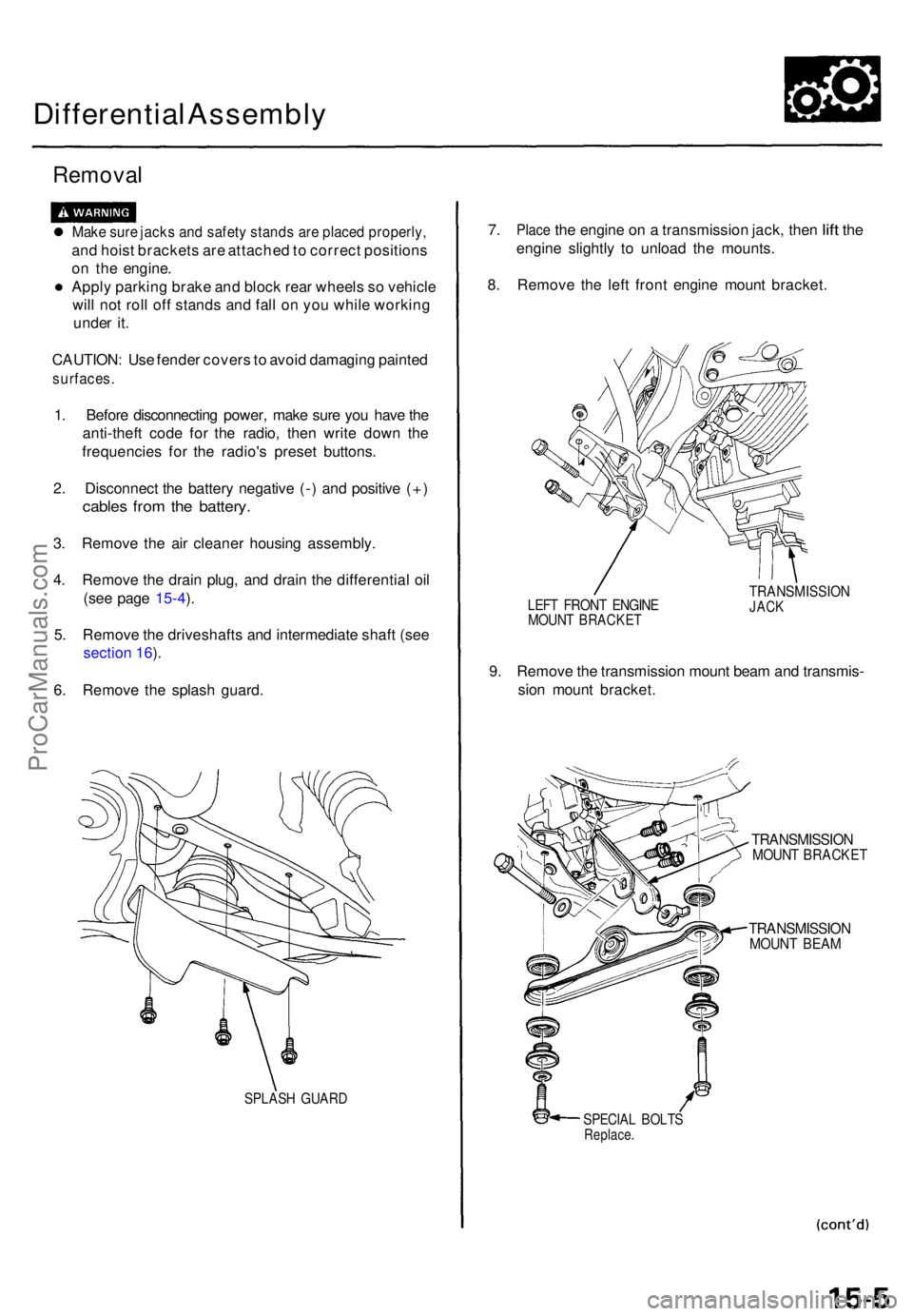
6 . Remov e th e splas h guard .
SPLAS H GUAR D
7. Plac e the engin e on a transmissio n jack , the n lift th e
engin e slightl y t o unloa d th e mounts .
8 . Remov e th e lef t fron t engin e moun t bracket .
LEFT FRON T ENGIN EMOUNT BRACKE T
TRANSMISSIO NJACK
9. Remov e th e transmissio n moun t bea m an d transmis -
sio n moun t bracket .
TRANSMISSIO NMOUNT BRACKE T
TRANSMISSIO NMOUNT BEA M
SPECIA L BOLT SReplace .
ProCarManuals.com
Page 1152 of 1771
System Description
System Operation (cont'd)
Hydraulic Control at Each Speed Range
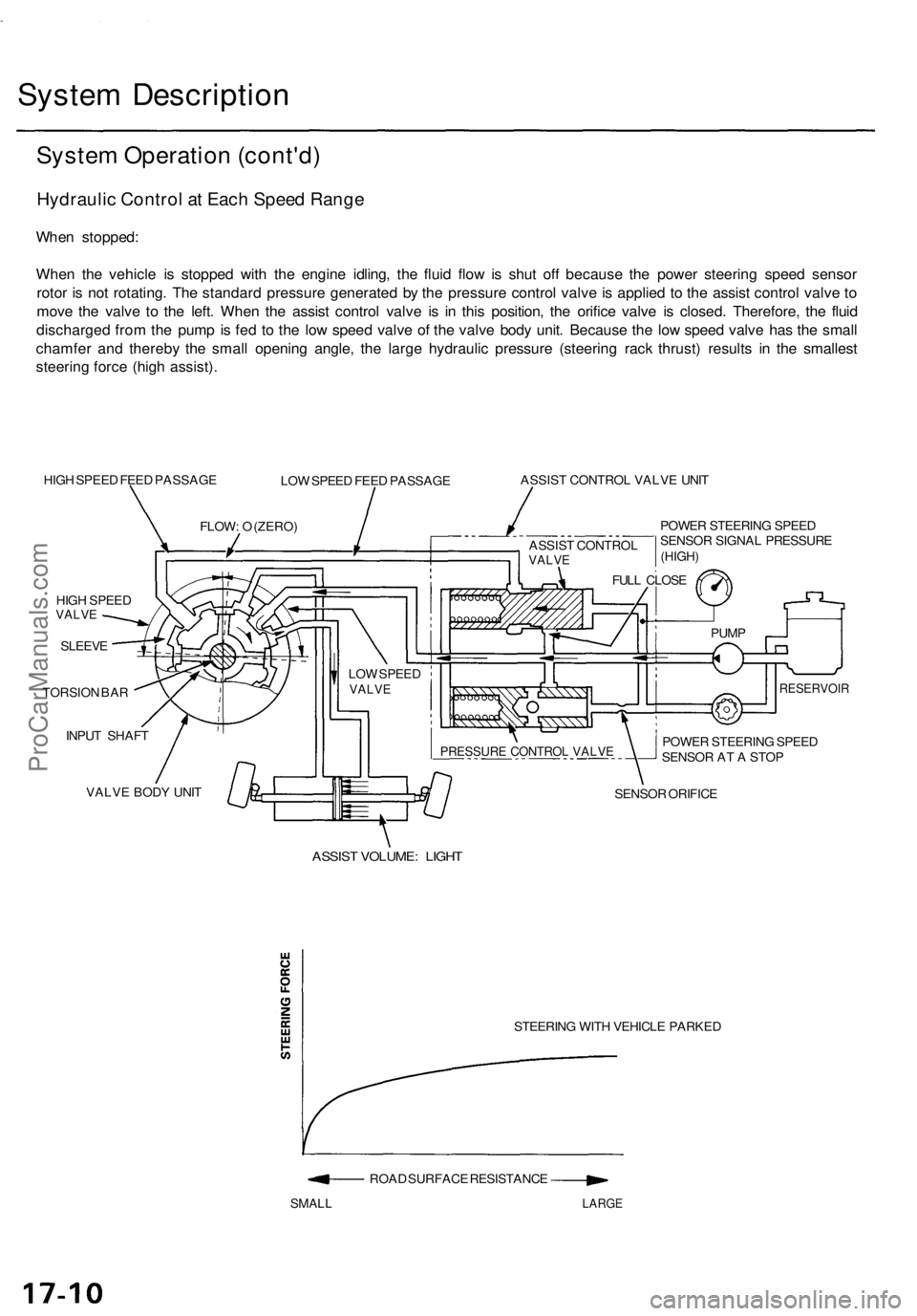
When stopped:
When the vehicle is stopped with the engine idling, the fluid flow is shut off because the power steering speed sensor
rotor is not rotating. The standard pressure generated by the pressure control valve is applied to the assist control valve to
move the valve to the left. When the assist control valve is in this position, the orifice valve is closed. Therefore, the fluid
discharged from the pump is fed to the low speed valve of the valve body unit. Because the low speed valve has the small
chamfer and thereby the small opening angle, the large hydraulic pressure (steering rack thrust) results in the smallest
steering force (high assist).
HIGH SPEED FEED PASSAGE
LOW SPEED FEED PASSAGE
ASSIST CONTROL VALVE UNIT
POWER STEERING SPEED
SENSOR SIGNAL PRESSURE
HIGH SPEED
VALVE
SLEEVE
TORSION BAR
INPUT SHAFT
VALVE BODY UNIT
SENSOR ORIFICE
ASSIST VOLUME: LIGHT
STEERING WITH VEHICLE PARKED
ROAD SURFACE RESISTANCE
SMALL
LARGE
FLOW: O (ZERO)
LOW SPEED
VALVE
POWER STEERING SPEED
SENSOR AT A STOP
RESERVOIR
PUMP
FULL CLOSE
PRESSURE CONTROL VALVE
(HIGH)
ASSIST CONTROL
VALVEProCarManuals.com
Page 1153 of 1771
Middle speed range:
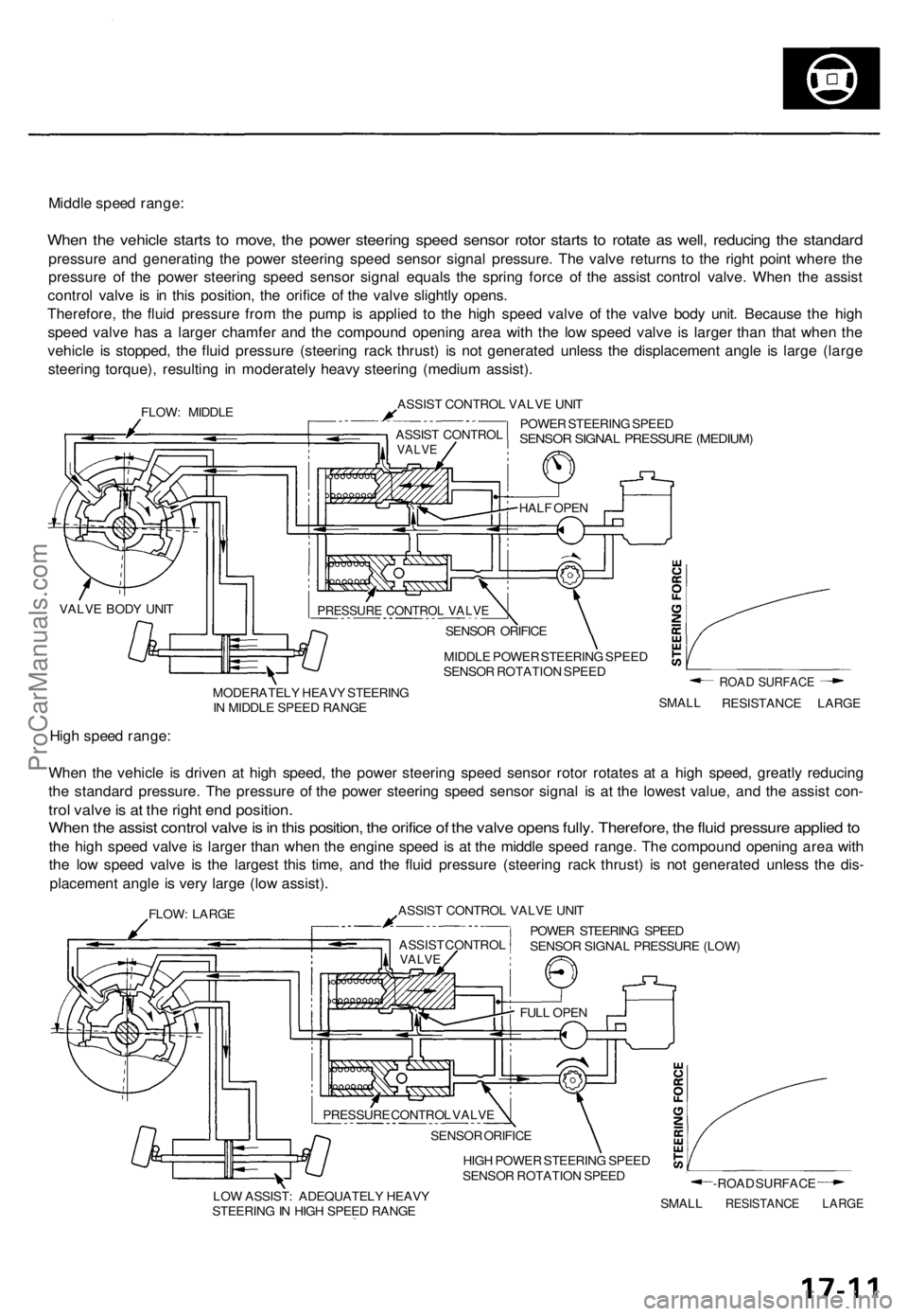
When the vehicle starts to move, the power steering speed sensor rotor starts to rotate as well, reducing the standard
pressure and generating the power steering speed sensor signal pressure. The valve returns to the right point where the
pressure of the power steering speed sensor signal equals the spring force of the assist control valve. When the assist
control valve is in this position, the orifice of the valve slightly opens.
Therefore, the fluid pressure from the pump is applied to the high speed valve of the valve body unit. Because the high
speed valve has a larger chamfer and the compound opening area with the low speed valve is larger than that when the
vehicle is stopped, the fluid pressure (steering rack thrust) is not generated unless the displacement angle is large (large
steering torque), resulting in moderately heavy steering (medium assist).
FLOW: MIDDLE
ASSIST CONTROL VALVE UNIT
POWER STEERING SPEED
SENSOR SIGNAL PRESSURE (MEDIUM)
MIDDLE POWER STEERING SPEED
SENSOR ROTATION SPEED
MODERATELY HEAVY STEERING
IN MIDDLE SPEED RANGE
SMALL
ROAD SURFACE
RESISTANCE LARGE
High speed range:
When the vehicle is driven at high speed, the power steering speed sensor rotor rotates at a high speed, greatly reducing
the standard pressure. The pressure of the power steering speed sensor signal is at the lowest value, and the assist con-
trol valve is at the right end position.
When the assist control valve is in this position, the orifice of the valve opens fully. Therefore, the fluid pressure applied to
the high speed valve is larger than when the engine speed is at the middle speed range. The compound opening area with
the low speed valve is the largest this time, and the fluid pressure (steering rack thrust) is not generated unless the dis-
placement angle is very large (low assist).
FLOW: LARGE
ASSIST CONTROL VALVE UNIT
POWER STEERING SPEED
SENSOR SIGNAL PRESSURE (LOW)
HIGH POWER STEERING SPEED
SENSOR ROTATION SPEED
LOW ASSIST: ADEQUATELY HEAVY
STEERING IN HIGH SPEED RANGE
SMALL
-ROAD SURFACE
RESISTANCE LARGE
PRESSURE CONTROL VALVE
SENSOR ORIFICE
HALF OPEN
ASSIST CONTROL
VALVE
VALVE BODY UNIT
ASSIST CONTROL
VALVE
FULL OPEN
SENSOR ORIFICE
PRESSURE CONTROL VALVEProCarManuals.com