1995 ACURA TL engine
[x] Cancel search: enginePage 895 of 1771
Idle Spee d Settin g
Inspection/Adjustmen t
NOTE:
• Befor e settin g th e idl e speed , chec k th e followin g
items:
— Th e MI L ha s no t bee n reporte d on .
— Ignitio n timin g
— Spar k plug s
— Ai r cleane r
— PC V syste m
• (Canada ) Pul l th e parkin g brak e leve r up . Star t th e
engine , the n chec k tha t th e headlight s ar e off .
1 . Star t th e engine . Hol d th e engine at 3,00 0 rp m wit h
no loa d (transmissio n i n o r position ) unti l th e
radiato r fa n come s on , the n le t i t idle .
2 . Connec t a tachometer .
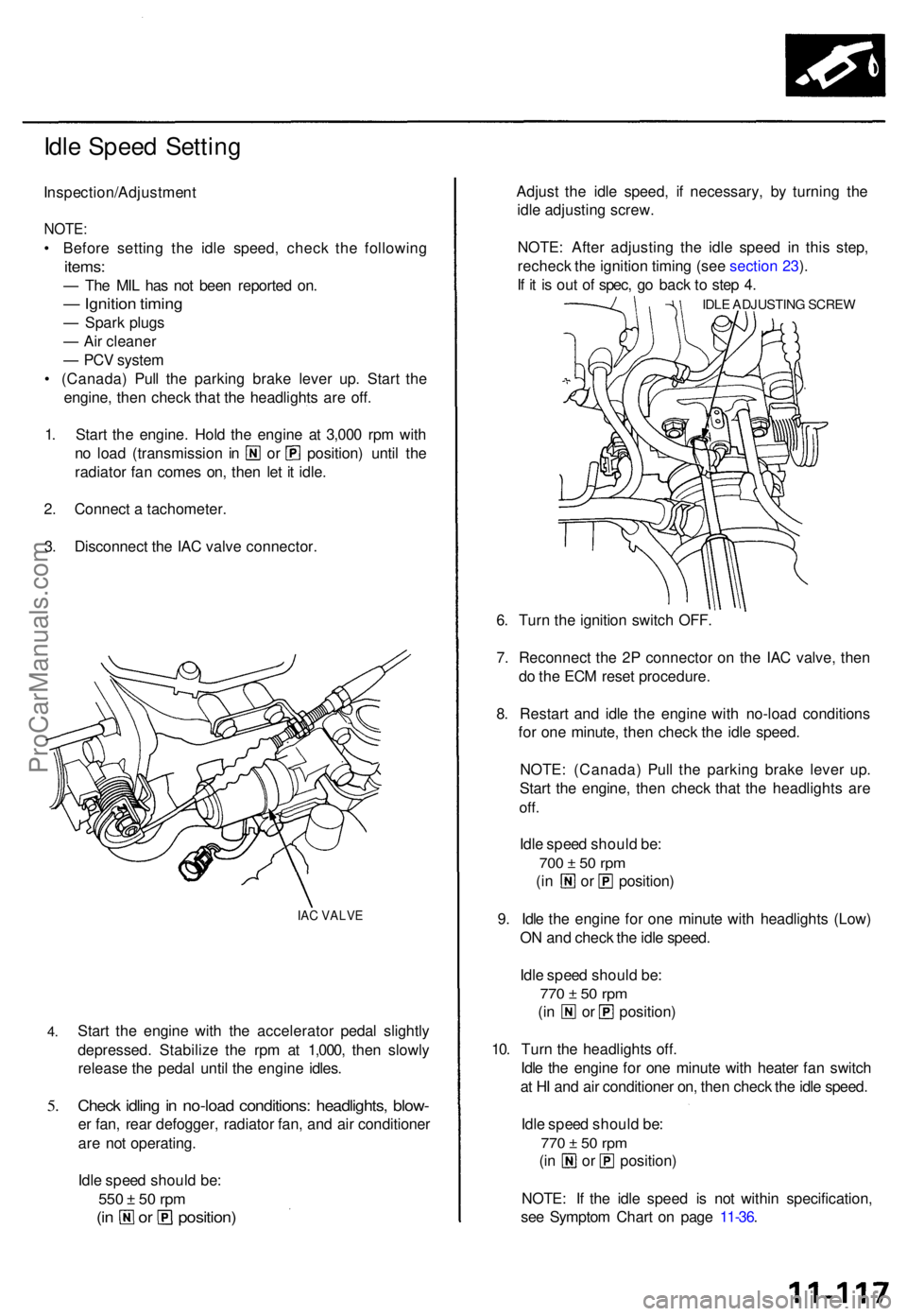
3 . Disconnec t th e IA C valv e connector .
IAC VALV E
4.
5.
Star t th e engin e wit h th e accelerato r peda l slightl y
depressed . Stabiliz e th e rp m a t 1,000 , the n slowl y
releas e th e peda l unti l th e engin e idles .
Check idlin g in no-loa d conditions : headlights , blow -
er fan , rea r defogger , radiato r fan , an d ai r conditione r
ar e no t operating .
Idl e spee d shoul d be :
550 ± 5 0 rp m
(in o r position )
Adjust th e idl e speed , i f necessary, by turnin g th e
idl e adjustin g screw .
NOTE : Afte r adjustin g th e idl e spee d i n thi s step ,
rechec k th e ignitio n timin g (se e sectio n 23 ).
I f i t i s ou t o f spec , g o bac k t o ste p 4 .
IDL E ADJUSTIN G SCRE W
6. Tur n th e ignitio n switc h OFF .
7 . Reconnec t th e 2 P connecto r o n th e IA C valve , the n
d o th e EC M rese t procedure .
8 . Restar t an d idl e th e engine with no-loa d condition s
fo r on e minute , the n chec k th e idl e speed .
NOTE : (Canada ) Pul l th e parkin g brak e leve r up .
Star t th e engine , the n chec k tha t th e headlight s ar e
off.
Idle spee d shoul d be :
700 ± 5 0 rp m
(in o r position )
9 . Idl e th e engin e fo r on e minut e wit h headlight s (Low )
O N an d chec k th e idl e speed .
Idl e spee d shoul d be :
770 ± 5 0 rp m
(in o r position )
10 . Tur n th e headlight s off .
Idl e th e engin e fo r on e minut e wit h heate r fa n switc h
a t H I an d ai r conditione r on , the n chec k th e idl e speed .
Idl e spee d shoul d be :
770 ± 5 0 rp m
(in o r position )
NOTE : I f th e idl e spee d i s no t withi n specification ,
se e Sympto m Char t o n pag e 11-36 .
ProCarManuals.com
Page 901 of 1771
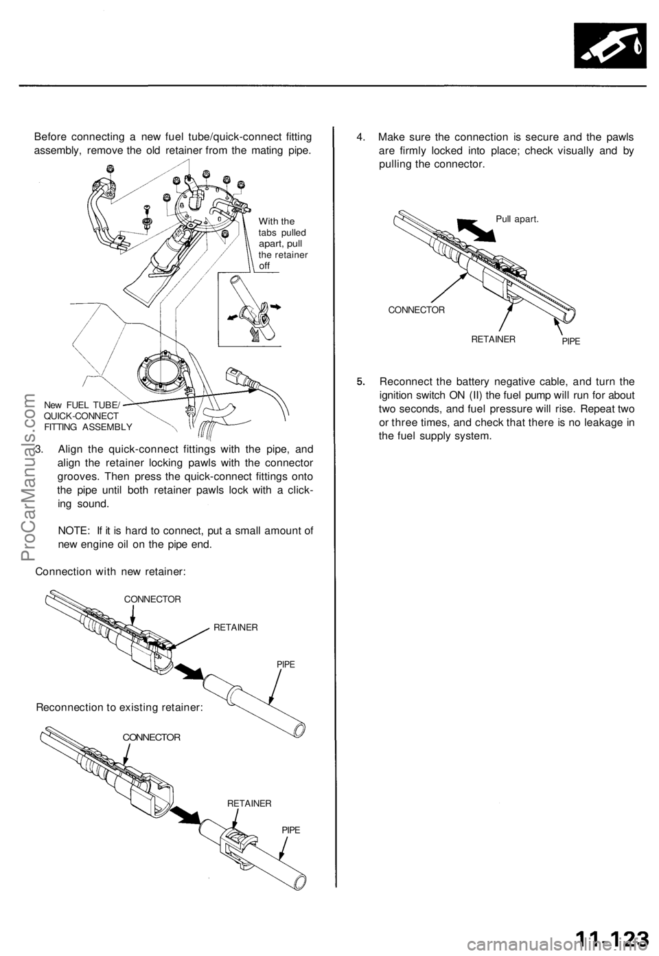
Before connecting a new fuel tube/quick-connect fitting
assembly, remove the old retainer from the mating pipe.
With the
tabs pulled
apart, pull
the retainer
off
New FUEL TUBE/
QUICK-CONNECT
FITTING ASSEMBLY
3. Align the quick-connect fittings with the pipe, and
align the retainer locking pawls with the connector
grooves. Then press the quick-connect fittings onto
the pipe until both retainer pawls lock with a click-
ing sound.
NOTE: If it is hard to connect, put a small amount of
new engine oil on the pipe end.
Connection with new retainer:
CONNECTOR
RETAINER
PIPE
CONNECTOR
RETAINER
PIPE
4. Make sure the connection is secure and the pawls
are firmly locked into place; check visually and by
pulling the connector.
Pull apart.
CONNECTOR
RETAINER
PIPE
Reconnect the battery negative cable, and turn the
ignition switch ON (II) the fuel pump will run for about
two seconds, and fuel pressure will rise. Repeat two
or three times, and check that there is no leakage in
the fuel supply system.
Reconnection to existing retainer:ProCarManuals.com
Page 902 of 1771
Fuel Supply System
System Description
The fuel supply system consists of a fuel tank, in-tank
high pressure fuel pump, PGM-FI main relay, fuel filter,
fuel pressure regulator, fuel injectors, and fuel delivery
and return lines. This system delivers pressure-regulat-
ed fuel to the fuel injectors and cuts the fuel delivery
when the engine is not running.
11-124ProCarManuals.com
Page 904 of 1771
Inspection (model s wit h servic e bolt )
1 . Reliev e fue l pressur e (se e pag e 11-124 ).
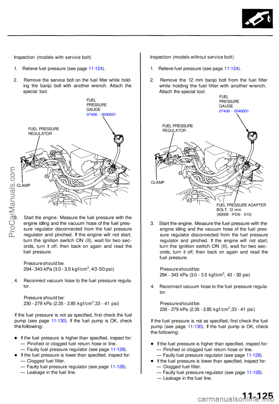
2 . Remov e th e servic e bol t o n th e fue l filte r whil e hold -
in g th e banj o bol t wit h anothe r wrench . Attac h th e
specia l tool .
FUELPRESSUR EGAUGE07406 - 004000 1
FUEL PRESSUR EREGULATO R
CLAMP
3. Star t th e engine . Measur e th e fue l pressur e wit h th e
engin e idlin g an d th e vacuu m hos e o f th e fue l pres -
sure regulato r disconnecte d fro m th e fue l pressur e
regulator an d pinched . I f th e engin e wil l no t start ,
turn th e ignitio n switc h O N (II) , wai t fo r tw o sec -
onds , tur n i t off , the n bac k o n agai n an d rea d th e
fue l pressure .
Pressur e shoul d be :
294 - 34 3 kP a (3. 0 - 3. 5 kgf/cm2, 43-5 0 psi )
4. Reconnec t vacuu m hos e to th e fue l pressur e regula -
tor.
Pressur e shoul d be :
23 0 - 27 9 kP a (2.3 5 - 2.8 5 kgf/cm2,3 3 - 4 1 psi )
I f th e fue l pressur e i s no t a s specified , firs t chec k th e fue l
pum p (se e pag e 11-130 ). I f th e fue l pum p i s OK , chec k
the following :
If th e fue l pressur e i s highe r tha n specified , inspec t for :
— Pinche d o r clogge d fue l retur n hos e o r line .
— Fault y fue l pressur e regulato r (se e pag e 11-128 ).
I f th e fue l pressur e is lowe r tha n specified , inspec t for :
— Clogge d fue l filter .
— Fault y fue l pressur e regulato r (se e pag e 11-128 ).
— Leakag e in th e fue l line . Inspectio
n (model s withou t servic e bolt )
1 . Reliev e fue l pressur e (se e pag e 11-124 ).
2 . Remov e th e 1 2 m m banj o bol t fro m th e fue l filte r
while holdin g th e fue l filte r wit h anothe r wrench .
Attach th e specia l tool .FUELPRESSUR EGAUGE07406 - 004000 1
FUEL PRESSUR EREGULATO R
CLAMP
FUEL PRESSUR E ADAPTE RBOLT, 1 2 m m(9000 8 -PD6 - 010 )
3. Star t th e engine . Measur e th e fue l pressur e wit h th e
engin e idlin g an d th e vacuu m hos e o f th e fue l pres -
sur e regulato r disconnecte d fro m th e fue l pressur e
regulato r an d pinched . I f th e engin e wil l no t start ,
turn th e ignitio n switc h O N (II) , wai t fo r tw o sec -
onds , tur n i t off , the n bac k o n agai n an d rea d th e
fue l pressure .
Pressur e shoul d be :
29 4 - 34 3 kP a (3. 0 - 3. 5 kgf/cm
2, 4 3 - 5 0 psi )
4 . Reconnec t vacuu m hos e to th e fue l pressur e regula -
tor.
Pressur e shoul d be :
23 0 - 27 9 kP a (2.3 5 - 2.8 5 kgf/cm2,3 3 - 4 1 psi )
I f th e fue l pressur e is no t a s specified , firs t chec k th e fue l
pum p (se e pag e 11-130 ). I f th e fue l pum p i s OK , chec k
the following :
If th e fue l pressur e is highe r tha n specified , inspec t for :
— Pinche d o r clogge d fue l retur n hos e o r line .
— Fault y fue l pressur e regulato r (se e pag e 11-128 ).
I f th e fue l pressur e is lowe r tha n specified , inspec t for :
— Clogged fuel filter .
— Fault y fue l pressur e regulato r (se e pag e 11-128 ).
— Leakag e in th e fue l line .
ProCarManuals.com
Page 907 of 1771
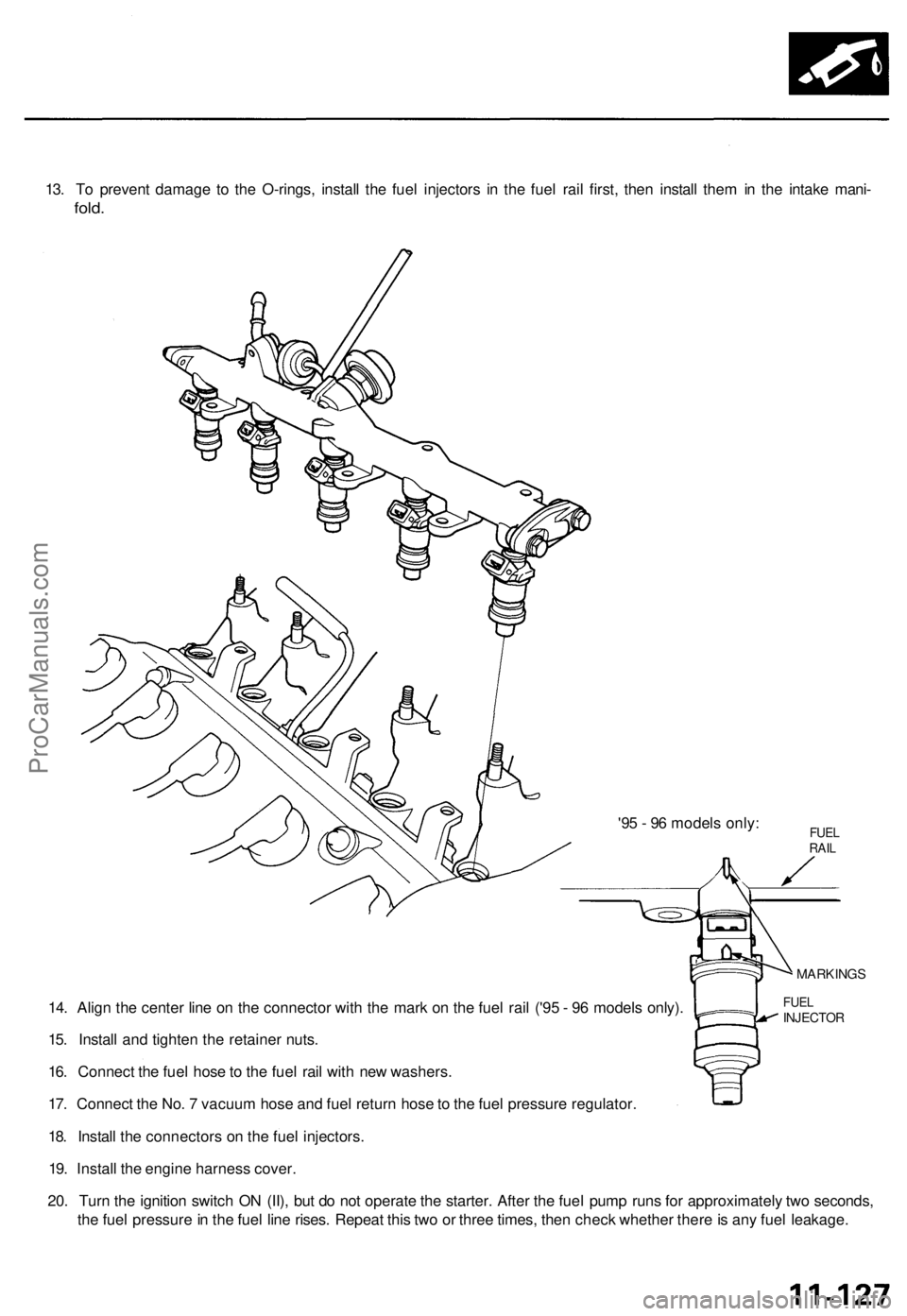
13. To prevent damage to the O-rings, install the fuel injectors in the fuel rail first, then install them in the intake mani-
fold.
'95 - 96 models only:
14. Align the center line on the connector with the mark on the fuel rail ('95 - 96 models only).
15. Install and tighten the retainer nuts.
16. Connect the fuel hose to the fuel rail with new washers.
17. Connect the No. 7 vacuum hose and fuel return hose to the fuel pressure regulator.
18. Install the connectors on the fuel injectors.
19. Install the engine harness cover.
20. Turn the ignition switch ON (II), but do not operate the starter. After the fuel pump runs for approximately two seconds,
the fuel pressure in the fuel line rises. Repeat this two or three times, then check whether there is any fuel leakage.
FUEL
INJECTOR
MARKINGS
FUEL
RAILProCarManuals.com
Page 914 of 1771
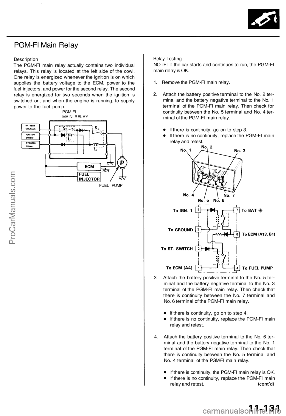
PGM-FI Main Relay
Description
The PGM-FI main relay actually contains two individual
relays. This relay is located at the left side of the cowl.
One relay is energized whenever the ignition is on which
supplies the battery voltage to the ECM, power to the
fuel injectors, and power for the second relay. The second
relay is energized for two seconds when the ignition is
switched on, and when the engine is running, to supply
power to the fuel pump.
PGM-FI
MAIN RELAY
FUEL PUMP
Relay Testing
NOTE: If the car starts and continues to run, the PGM-FI
main relay is OK.
1. Remove the PGM-FI main relay.
2.
Attach the battery positive terminal to the No. 2 ter-
minal and the battery negative terminal to the No. 1
terminal of the PGM-FI main relay. Then check for
continuity between the No. 5 terminal and No. 4 ter-
minal of the PGM-FI main relay.
If there is continuity, go on to step 3.
If there is no continuity, replace the PGM-FI main
relay and retest.
3. Attach the battery positive terminal to the No. 5 ter-
minal and the battery negative terminal to the No. 3
terminal of the PGM-FI main relay. Then check that
there is continuity between the No. 7 terminal and
No. 6 terminal of the PGM-FI main relay.
If there is continuity, go on to step 4.
If there is no continuity, replace the PGM-FI main
relay and retest.
4. Attach the battery positive terminal to the No. 6 ter-
minal and the battery negative terminal to the No. 1
terminal of the PGM-FI main relay. Then check that
there is continuity between the No. 5 terminal and
No. 4 terminal of the PGM-FI main relay.
If there is continuity, the PGM-FI main relay is OK.
If there is no continuity, replace the PGM-FI main
relay and retest.ProCarManuals.com
Page 915 of 1771
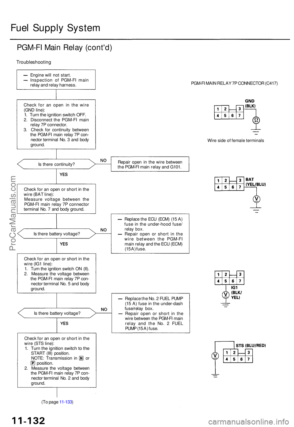
Fuel Suppl y Syste m
PGM-F I Mai n Rela y (cont'd )
Troubleshootin g
Engine wil l no t start .
Inspectio n o f PGM-F I mai n
rela y an d rela y harness .
Chec k fo r a n ope n i n th e wir e
(GN D line) :
1. Tur n th e ignitio n switc h OFF .2. Disconnec t th e PGM-F I mai n
rela y 7 P connector .
3 . Chec k fo r continuit y betwee n
th e PGM-F I mai n rela y 7 P con -
necto r termina l No . 3 an d bod y
ground .
I s ther e continuity ?
Chec k fo r a n ope n o r shor t i n th e
wir e (BA T line) :
Measur e voltag e betwee n th e
PGM-F I mai n rela y 7 P connecto r
termina l No . 7 an d bod y ground .
I s ther e batter y voltage ?
Chec k fo r a n ope n o r shor t i n th e
wir e (IG 1 line) :
1 . Tur n th e ignitio n switc h O N (II) .
2 . Measur e th e voltag e betwee n
th e PGM-F I mai n rela y 7 P con -
necto r termina l No . 5 an d bod y
ground .
I s ther e batter y voltage ?
Chec k fo r a n ope n o r shor t i n th e
wir e (ST S line) :
1. Tur n th e ignitio n switc h to th eSTAR T (III ) position .NOTE: Transmissio n i n o rposition .2. Measur e th e voltag e betwee n
th e PGM-F I mai n rela y 7 P con -
necto r termina l No . 2 an d bod y
ground .
(T o pag e 11-133 ) PGM-F
I MAI N RELA Y 7 P CONNECTO R (C417 )
Wir e sid e o f femal e terminal s
Repai r ope n in th e wir e betwee n
th e PGM-F I mai n rela y an d G101 .
Replac e th e EC U (ECM ) (1 5 A )
fus e i n th e under-hoo d fuse /
relay box .Repai r ope n o r shor t i n th e
wir e betwee n th e PGM-F I
mai n rela y an d th e EC U (ECM )
(1 5 A ) fuse .
Replac e th e No . 2 FUE L PUM P
(1 5 A ) fus e in th e under-das h
fuse/rela y box .
Repai r ope n o r shor t i n th e
wir e betwee n th e PGM-F I mai n
rela y an d th e No . 2 FUE L
PUM P (1 5 A ) fuse .
ProCarManuals.com
Page 917 of 1771
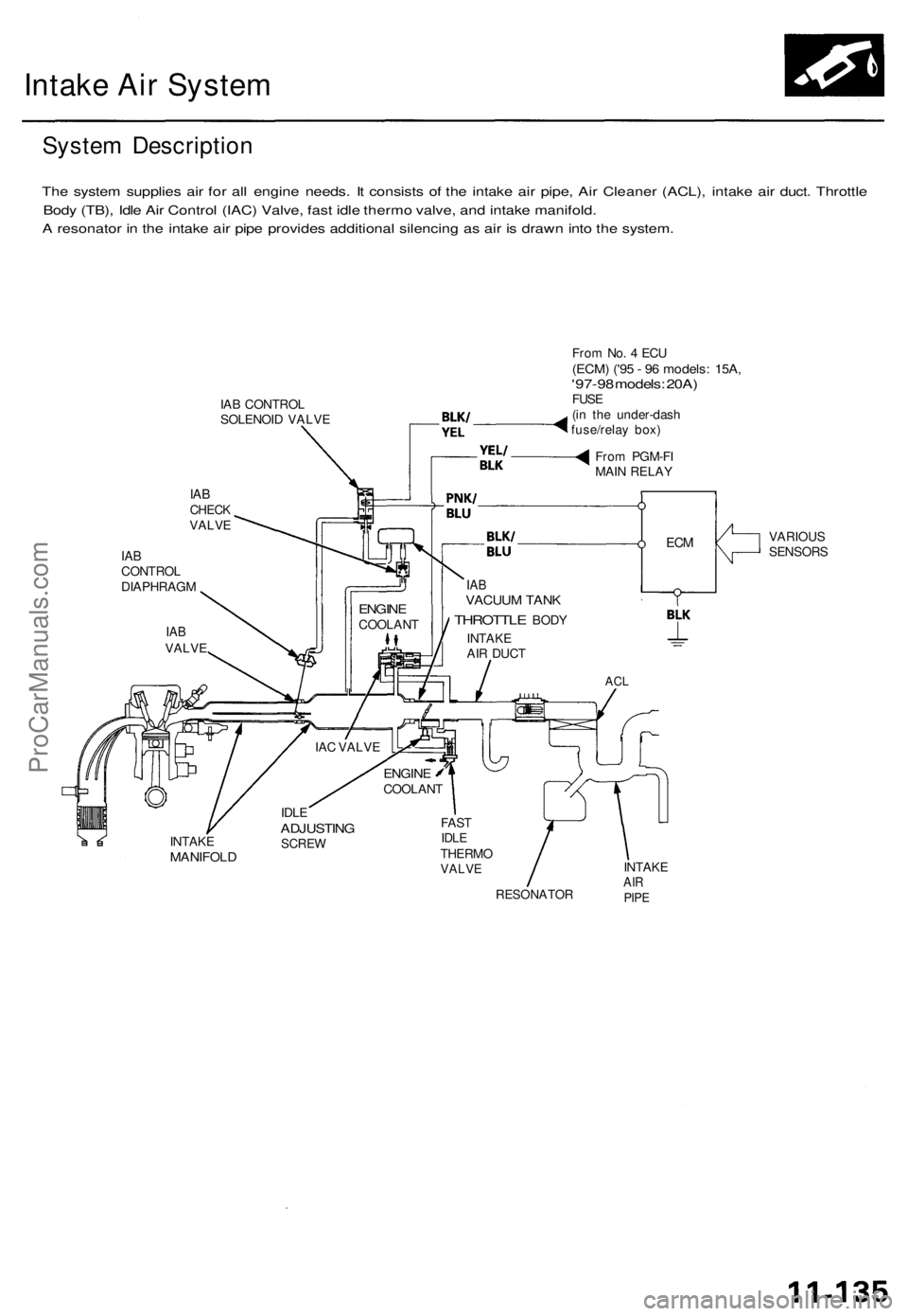
Intake Air System
System Description
The system supplies air for all engine needs. It consists of the intake air pipe, Air Cleaner (ACL), intake air duct. Throttle
Body (TB), Idle Air Control (IAC) Valve, fast idle thermo valve, and intake manifold.
A resonator in the intake air pipe provides additional silencing as air is drawn into the system.
IAB CONTROL
SOLENOID VALVE
IAB
CHECK
VALVE
IAB
CONTROL
DIAPHRAGM
From No. 4 ECU
(ECM) ('95 - 96 models: 15A,
'97-98 models: 20A)
FUSE
(in the under-dash
fuse/relay box)
From PGM-FI
MAIN RELAY
VARIOUS
SENSORS
IAB
VACUUM TANK
THROTTLE
BODY
INTAKE
AIR DUCT
ACL
INTAKE
MANIFOLD
IDLE
ADJUSTING
SCREW
FAST
IDLE
THERMO
VALVE
RESONATOR
INTAKE
AIR
PIPE
IAC VALVE
ENGINE
COOLANT
ENGINE
COOLANT
IAB
VALVE
ECMProCarManuals.com