Page 946 of 1771
In or position, the optimum gear is automatically selected from 1st, 2nd, 3rd, and 4th gears, according to conditions
such as the balance between throttle opening (engine load) and vehicle speed.
or Position, 1st gear
1. Hydraulic pressure is applied to the 1st clutch, which rotates together with the mainshaft, and the mainshaft 1st gear
rotates.
2. Power is transmitted to the countershaft 1st gear, which drives the countershaft via the one-way clutch.
3. Power is transmitted to the secondary drive gear, which drives the secondary driven gear.
NOTE: In or position, hydraulic pressure is not applied to the 1st-hold clutch.
TORQUE CONVERTER
MAINSHAFT 1ST GEAR
1ST CLUTCH
MAINSHAFT
COUNTERSHAFT
COUNTERSHAFT
1ST GEAR
ONE-WAY CLUTCH
SECONDARY DRIVEN GEAR
PARKING GEAR
SECONDARY
DRIVE GEARProCarManuals.com
Page 951 of 1771
Description
The electronic control system consists of the Transmission Control Module (TCM), sensors, a linear solenoid, and four
solenoid valves.
Shift and lock-up are electronically controlled for comfortable driving under all conditions.
The TCM is located below the dashboard, behind the glove box on the passenger's side.
TCM
Linear Solenoid
Shift Control
Solenoid Valve A
Shift Control
Solenoid Valve B
Lock-up Control
Solenoid Valve A
Lock-up Control
Solenoid Valve B
Engine Speed Signal
Brake Switch Signal
Mainshaft Speed Sensor
Signal
Countershaft Speed
Sensor Signal
Vehicle Speed Sensor
Signal
Indicator Light
Self-Diagnosis Signal
Electronic Control System
Shift Control
Lock-up Control
Throttle Position
Sensor Signal
Engine Coolant
Temperature
Sensor Signal
Service Check
Connector
Barometric
Pressure Sensor
INTERLOCK
CONTROL UNIT
Self-Diagnosis
FunctionProCarManuals.com
Page 953 of 1771
Description
GRADE LOGIC CONTROL SYSTEM
How it works:
The TCM compares actual driving conditions with driving conditions memorized in the TCM, based on the input from the
vehicle speed sensor, throttle position sensor, engine coolant temperature sensor, barometric pressure sensor, brake
switch signal and shift lever position signal, to control shifting while a vehicle is ascending or descending a slope, or
reducing speed.
SENSORS
SIGNALS DETECTED
TCM
Electronic Control System (cont'd)ProCarManuals.com
Page 954 of 1771

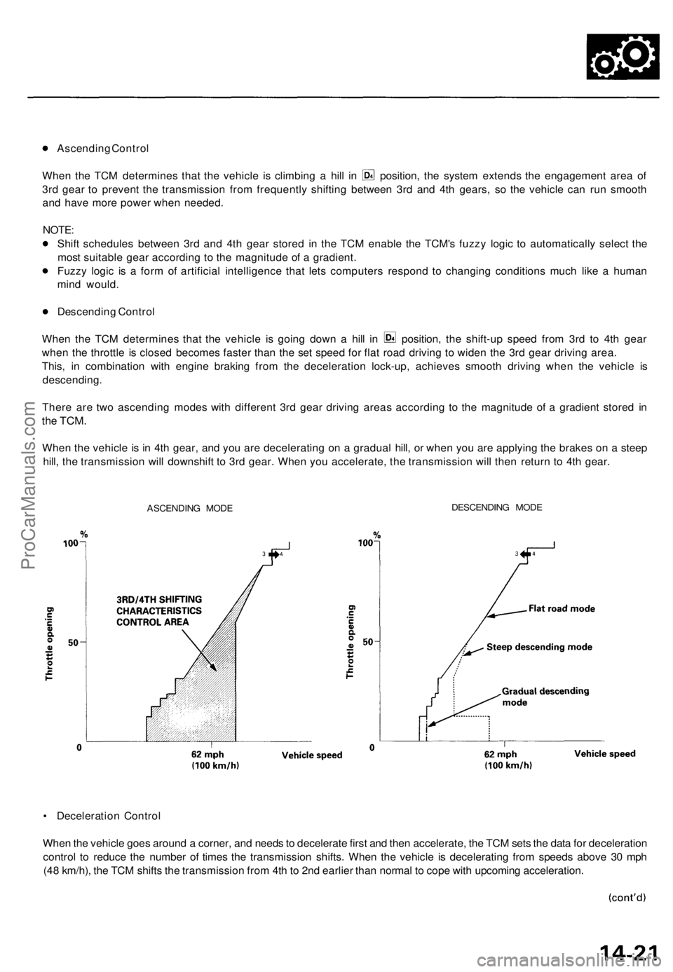
Ascending Control
When the TCM determines that the vehicle is climbing a hill in position, the system extends the engagement area of
3rd gear to prevent the transmission from frequently shifting between 3rd and 4th gears, so the vehicle can run smooth
and have more power when needed.
NOTE:
Shift schedules between 3rd and 4th gear stored in the TCM enable the TCM's fuzzy logic to automatically select the
most suitable gear according to the magnitude of a gradient.
Fuzzy logic is a form of artificial intelligence that lets computers respond to changing conditions much like a human
mind would.
Descending Control
When the TCM determines that the vehicle is going down a hill in position, the shift-up speed from 3rd to 4th gear
when the throttle is closed becomes faster than the set speed for flat road driving to widen the 3rd gear driving area.
This, in combination with engine braking from the deceleration lock-up, achieves smooth driving when the vehicle is
descending.
There are two ascending modes with different 3rd gear driving areas according to the magnitude of a gradient stored in
the
TCM.
When the vehicle is in 4th gear, and you are decelerating on a gradual hill, or when you are applying the brakes on a steep
hill, the transmission will downshift to 3rd gear. When you accelerate, the transmission will then return to 4th gear.
ASCENDING MODE
DESCENDING MODE
• Deceleration Control
When the vehicle goes around a corner, and needs to decelerate first and then accelerate, the TCM sets the data for deceleration
control to reduce the number of times the transmission shifts. When the vehicle is decelerating from speeds above 30 mph
(48 km/h), the TCM shifts the transmission from 4th to 2nd earlier than normal to cope with upcoming acceleration.ProCarManuals.com
Page 955 of 1771

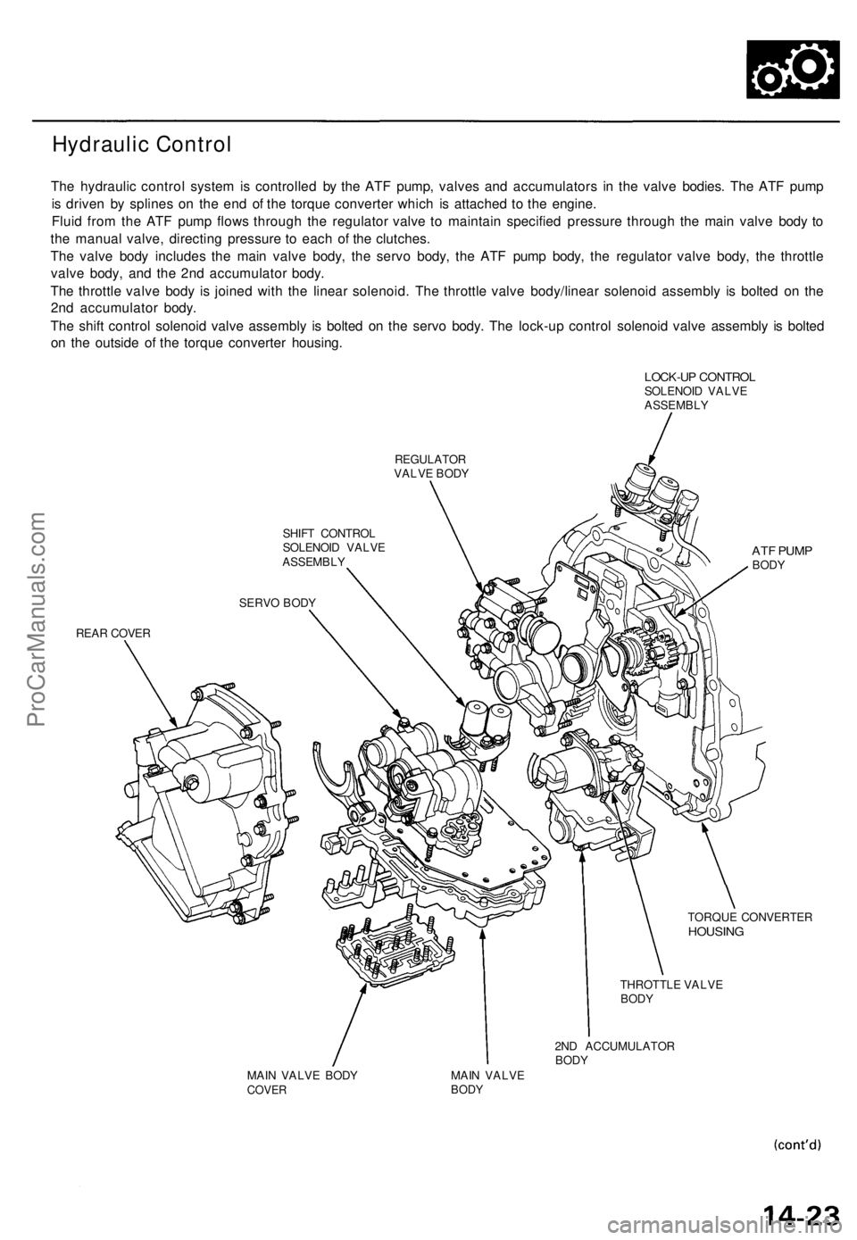
Hydraulic Control
The hydrauli c contro l syste m is controlle d b y th e AT F pump , valve s an d accumulator s i n th e valv e bodies . Th e AT F pum p
i s drive n b y spline s o n th e en d o f th e torqu e converte r whic h i s attache d t o th e engine .
Flui d fro m th e AT F pum p flow s throug h th e regulato r valv e t o maintai n specifie d pressur e throug h th e mai n valv e bod y t o
th e manua l valve , directin g pressur e t o eac h o f th e clutches .
Th e valv e bod y include s th e mai n valv e body , th e serv o body , th e AT F pum p body , th e regulato r valv e body , th e throttl e
valv e body , an d th e 2n d accumulato r body .
Th e throttl e valv e bod y i s joine d wit h th e linea r solenoid . Th e throttl e valv e body/linea r solenoi d assembl y i s bolte d o n th e
2n d accumulato r body .
Th e shif t contro l solenoi d valv e assembl y i s bolte d o n th e serv o body . Th e lock-u p contro l solenoi d valv e assembl y i s bolte d
o n th e outsid e o f th e torqu e converte r housing .
LOCK-UP CONTRO LSOLENOI D VALV E
ASSEMBL Y
REGULATO RVALVE BOD Y
SHIF T CONTRO L
SOLENOI D VALV E
ASSEMBL Y
REA R COVE R
ATF PUM PBODY
TORQU E CONVERTE RHOUSING
THROTTL E VALV EBODY
2ND ACCUMULATO RBODYMAIN VALV E BOD YCOVE RMAIN VALV EBODY
SERV O BOD Y
ProCarManuals.com
Page 959 of 1771

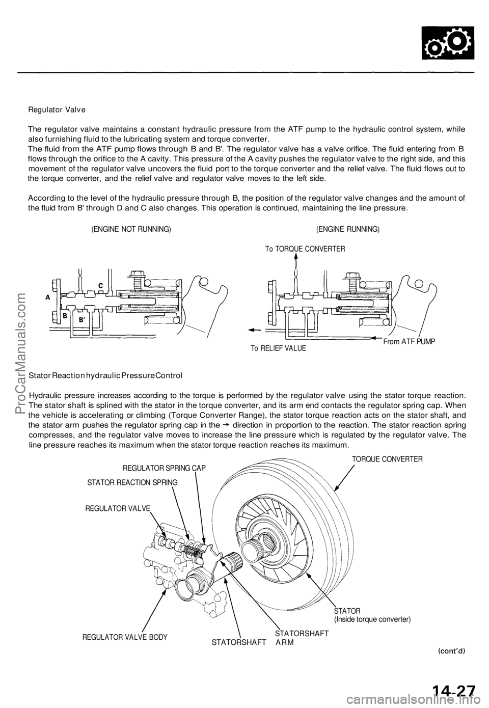
Regulator Valv e
The regulato r valv e maintain s a constan t hydrauli c pressur e fro m th e AT F pum p t o th e hydrauli c contro l system , whil e
als o furnishin g flui d to th e lubricatin g syste m an d torqu e converter .
The flui d fro m th e AT F pum p flow s throug h B an d B' . Th e regulato r valv e ha s a valv e orifice . Th e flui d enterin g fro m B
flow s throug h th e orific e to th e A cavity . Thi s pressur e o f th e A cavit y pushe s th e regulato r valv e to th e righ t side , an d thi s
movemen t o f th e regulato r valv e uncover s th e flui d por t t o th e torqu e converte r an d th e relie f valve . Th e flui d flow s ou t t o
th e torqu e converter , an d th e relie f valv e an d regulato r valv e move s t o th e lef t side .
Accordin g to th e leve l o f th e hydrauli c pressur e throug h B , th e positio n o f th e regulato r valv e change s an d th e amoun t o f
th e flui d fro m B ' throug h D an d C als o changes . Thi s operatio n is continued , maintainin g th e lin e pressure .
(ENGINE NO T RUNNING )(ENGINE RUNNING )
To TORQU E CONVERTE R
To RELIE F VALU EFrom AT F PUM P
Stato r Reactio n hydrauli c Pressur e Contro l
Hydrauli c pressur e increase s accordin g t o th e torqu e is performe d b y th e regulato r valv e usin g th e stato r torqu e reaction .
Th e stato r shaf t i s spline d wit h th e stato r i n th e torqu e converter , an d it s ar m en d contact s th e regulato r sprin g cap . Whe n
th e vehicl e is acceleratin g o r climbin g (Torqu e Converte r Range) , th e stato r torqu e reactio n act s o n th e stato r shaft , an d
the stato r ar m pushe s th e regulato r sprin g ca p in th e directio n in proportio n t o th e reaction . Th e stato r reactio n sprin g
compresses , an d th e regulato r valv e move s t o increas e th e lin e pressur e whic h i s regulate d b y th e regulato r valve . Th e
lin e pressur e reache s it s maximu m whe n th e stato r torqu e reactio n reache s it s maximum .
REGULATO R SPRIN G CA P
STATO R REACTIO N SPRIN G
REGULATO R VALV E
REGULATO R VALV E BOD Y
TORQU E CONVERTE R
STATOR(Inside torqu e converter )
STATOR SHAF TSTATO R SHAF T AR M
ProCarManuals.com
Page 962 of 1771
Description
Position
As the engine turns, the ATF pump also starts to operate. Automatic transmission fluid (ATF) is drawn from (99) and dis-
charged into (1). Then, ATF flowing from the ATF pump becomes the line pressure (1). The line pressure (1) is regulated
by the regulator valve. The torque converter inlet pressure (92) enters (94) of the torque converter through the lock-up
shift valve and discharges into (90).
The torque converter check valve prevents the torque converter pressure from rising.
Under this condition, the hydraulic pressure is not applied to the clutches as the manual valve stops line pressure (1).
NOTE: When used, "left" or "right" indicates direction on the hydraulic circuit.
Hydraulic Flow (cont'd)ProCarManuals.com
Page 965 of 1771

Position
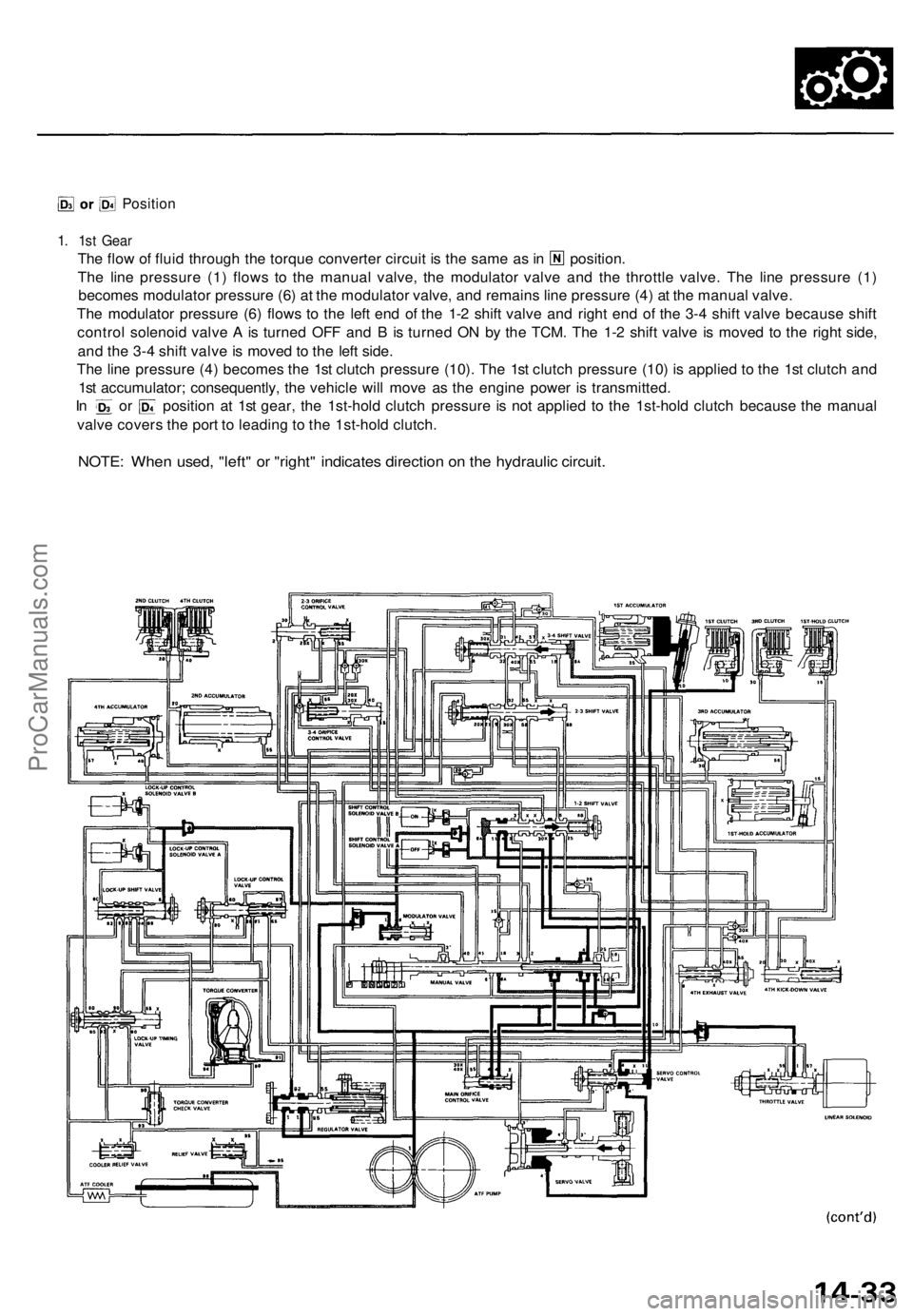
1. 1st Gear
The flow of fluid through the torque converter circuit is the same as in position.
The line pressure (1) flows to the manual valve, the modulator valve and the throttle valve. The line pressure (1)
becomes modulator pressure (6) at the modulator valve, and remains line pressure (4) at the manual valve.
The modulator pressure (6) flows to the left end of the 1-2 shift valve and right end of the 3-4 shift valve because shift
control solenoid valve A is turned OFF and B is turned ON by the TCM. The 1-2 shift valve is moved to the right side,
and the 3-4 shift valve is moved to the left side.
The line pressure (4) becomes the 1st clutch pressure (10). The 1st clutch pressure (10) is applied to the 1st clutch and
1st accumulator; consequently, the vehicle will move as the engine power is transmitted.
In or position at 1st gear, the 1st-hold clutch pressure is not applied to the 1st-hold clutch because the manual
valve covers the port to leading to the 1st-hold clutch.
NOTE: When used, "left" or "right" indicates direction on the hydraulic circuit.ProCarManuals.com