1995 ACURA TL engine
[x] Cancel search: enginePage 853 of 1771
![ACURA TL 1995 Service Repair Manual
System Description
System Connectors [Engine Compartment] (cont'd)
C309
ENGINE
WIRE
HARNESS
G101 C322
C110
C122
C123
C119 ('95-96 models)
C115/C320
C114/C321
C332
('97-98 mo ACURA TL 1995 Service Repair Manual
System Description
System Connectors [Engine Compartment] (cont'd)
C309
ENGINE
WIRE
HARNESS
G101 C322
C110
C122
C123
C119 ('95-96 models)
C115/C320
C114/C321
C332
('97-98 mo](/manual-img/32/56993/w960_56993-852.png)
System Description
System Connectors [Engine Compartment] (cont'd)
C309
ENGINE
WIRE
HARNESS
G101 C322
C110
C122
C123
C119 ('95-96 models)
C115/C320
C114/C321
C332
('97-98 models)
C326
'95 - 96 models)
C331
('97-98 models)
C330
('97-98 models)
C314
MAIN WIRE
HARNESS
C121
C317
C127
C126
C118
C116/C319
C117ProCarManuals.com
Page 862 of 1771
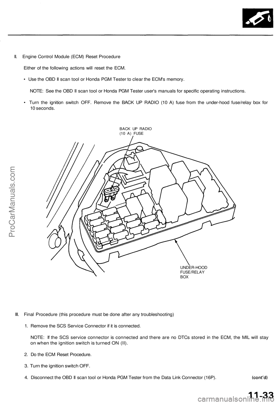
II. Engine Control Module (ECM) Reset Procedure
Either of the following actions will reset the ECM.
• Use the OBD II scan tool or Honda PGM Tester to clear the ECM's memory.
NOTE: See the OBD II scan tool or Honda PGM Tester user's manuals for specific operating instructions.
• Turn the ignition switch OFF. Remove the BACK UP RADIO (10 A) fuse from the under-hood fuse/relay box for
10 seconds.
BACK UP RADIO
(10 A) FUSE
UNDER-HOOD
FUSE/RELAY
BOX
III. Final Procedure (this procedure must be done after any troubleshooting)
1. Remove the SCS Service Connector if it is connected.
NOTE: If the SCS service connector is connected and there are no DTCs stored in the ECM, the MIL will stay
on when the ignition switch is turned ON (II).
2. Do the ECM Reset Procedure.
3. Turn the ignition switch OFF.
4. Disconnect the OBD II scan tool or Honda PGM Tester from the Data Link Connector (16P).ProCarManuals.com
Page 864 of 1771
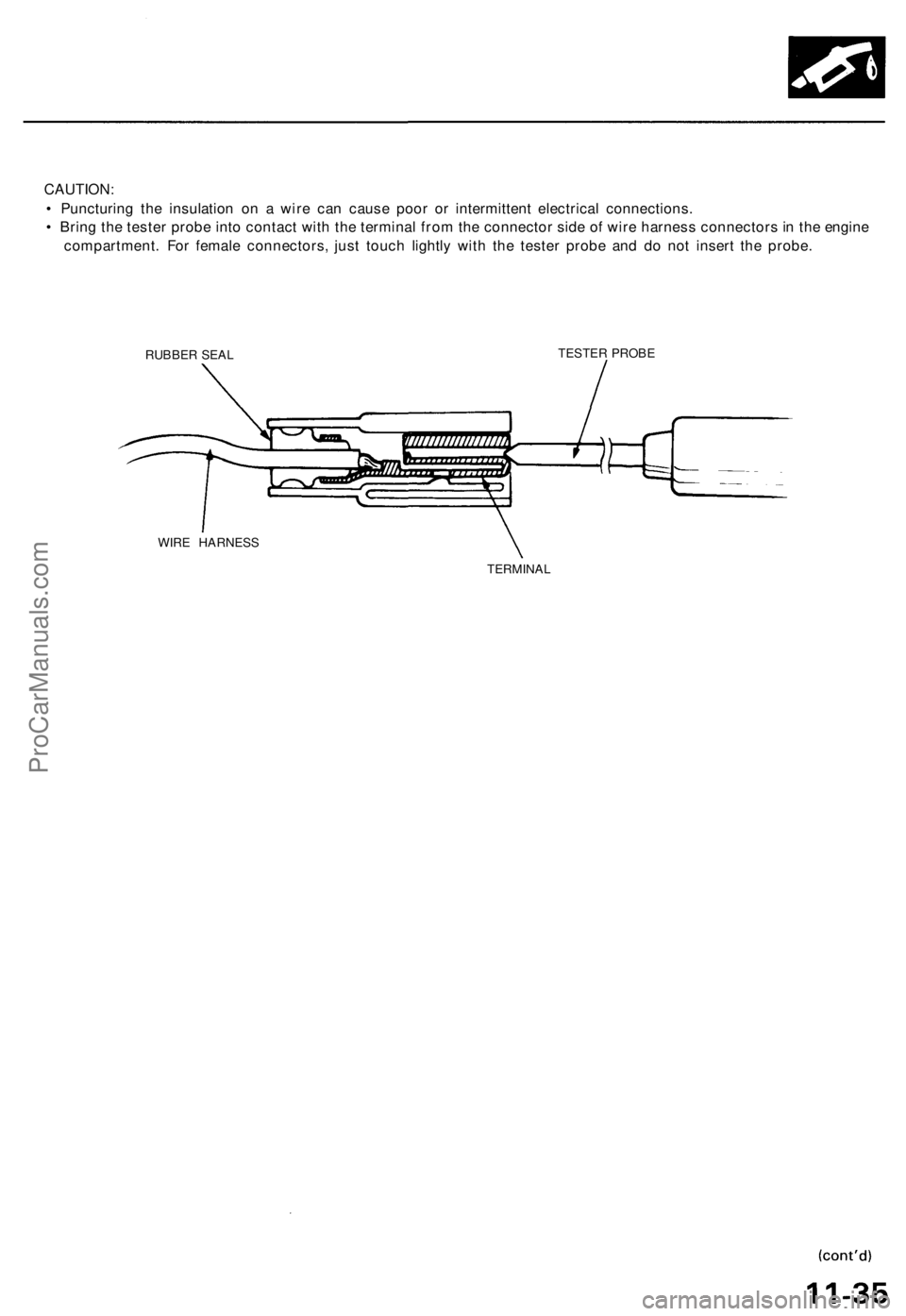
CAUTION:
• Puncturing the insulation on a wire can cause poor or intermittent electrical connections.
• Bring the tester probe into contact with the terminal from the connector side of wire harness connectors in the engine
compartment. For female connectors, just touch lightly with the tester probe and do not insert the probe.
RUBBER SEAL
TESTER PROBE
WIRE HARNESS
TERMINALProCarManuals.com
Page 867 of 1771
Troubleshooting
Troubleshooting Procedures (cont'd)
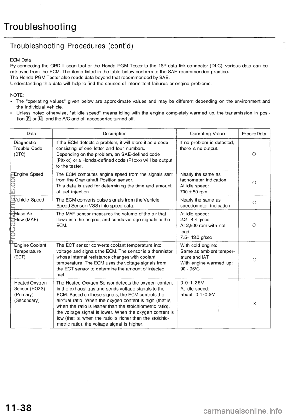
ECM Data
By connecting the OBD II scan tool or the Honda PGM Tester to the 16P data link connector (DLC), various data can be
retrieved from the ECM. The items listed in the table below conform to the SAE recommended practice.
The Honda PGM Tester also reads data beyond that recommended by SAE.
Understanding this data will help to find the causes of intermittent failures or engine problems.
NOTE:
• The "operating values" given below are approximate values and may be different depending on the environment and
the individual vehicle.
• Unless noted otherwise, "at idle speed" means idling with the engine completely warmed up, the transmission in posi-
tion or , and the A/C and all accessories turned off.
Data
Description
Operating Value
Freeze Data
Diagnostic
Trouble Code
(DTC)
If the ECM detects a problem, it will store it as a code
consisting of one letter and four numbers.
Depending on the problem, an SAE-defined code
(P0xxx)
or a
Honda-defined code
(P1xxx)
will
be
output
to the tester.
If no problem is detected,
there is no output.
Engine Speed
The ECM computes engine speed from the signals sent
from the Crankshaft Position sensor.
This data is used for determining the time and amount
of fuel injection.
Nearly the same as
tachometer indication
At idle speed:
700 ± 50 rpm
Vehicle Speed
The ECM converts pulse signals from the Vehicle
Speed Sensor (VSS) into speed data.
Nearly the same as
speedometer indication
Mass Air
Flow (MAF)
The MAF sensor measures the volume of the air that
flows into the engine, and sends voltage signals to the
ECM.
At idle speed:
2.2 - 4.4 g/sec
At 2,500 rpm with not
load:
7.5- 13.0 g/sec
Engine Coolant
Temperature
(ECT)
The ECT sensor converts coolant temperature into
voltage and signals the ECM. The sensor is a thermistor
whose internal resistance changes with coolant
temperature. The ECM uses the voltage signals from
the ECT sensor to determine the amount of injected
fuel.
With cold engine:
Same as ambient temper-
ature and IAT
With engine warmed up:
90 - 96°C
Heated Oxygen
Sensor (HO2S)
(Primary)
(Secondary)
The Heated Oxygen Sensor detects the oxygen content
in the exhaust gas and sends voltage signals to the
ECM. Based on these signals, the ECM controls the
air/fuel ratio. When the oxygen content is high (that is,
when the ratio is leaner than the stoichiometric ratio),
the voltage signal is lower. When the oxygen content is
low (that is, when the ratio is richer than the stoichio-
metric ratio), the voltage signal is higher.
0.0-1.25V
At idle speed:
about 0.1-0.9VProCarManuals.com
Page 868 of 1771
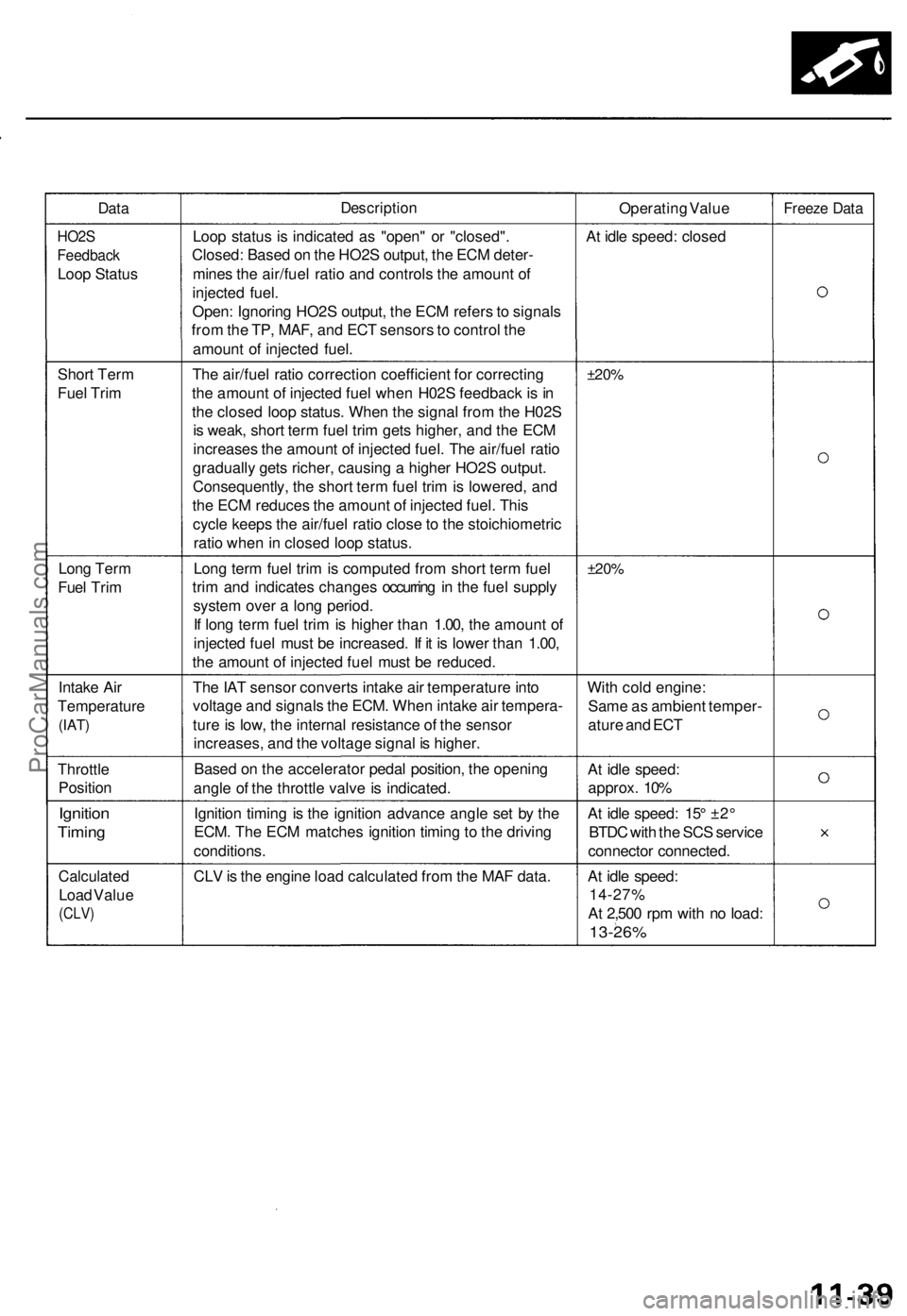
Data
Description
Operating Value
Freeze Data
HO2S
Feedback
Loop Status
Loop status is indicated as "open" or "closed".
Closed: Based on the HO2S output, the ECM deter-
mines the air/fuel ratio and controls the amount of
injected fuel.
Open: Ignoring HO2S output, the ECM refers to signals
from the TP, MAF, and ECT sensors to control the
amount of injected fuel.
At idle speed: closed
Short Term
Fuel Trim
The air/fuel ratio correction coefficient for correcting
the amount of injected fuel when H02S feedback is in
the closed loop status. When the signal from the H02S
is weak, short term fuel trim gets higher, and the ECM
increases the amount of injected fuel. The air/fuel ratio
gradually gets richer, causing a higher HO2S output.
Consequently, the short term fuel trim is lowered, and
the ECM reduces the amount of injected fuel. This
cycle keeps the air/fuel ratio close to the stoichiometric
ratio when in closed loop status.
±20%
Long Term
Fuel Trim
Long term fuel trim is computed from short term fuel
trim and indicates changes occurring in the fuel supply
system over a long period.
If long term fuel trim is higher than 1.00, the amount of
injected fuel must be increased. If it is lower than 1.00,
the amount of injected fuel must be reduced.
±20%
Intake Air
Temperature
(IAT)
The IAT sensor converts intake air temperature into
voltage and signals the ECM. When intake air tempera-
ture is low, the internal resistance of the sensor
increases, and the voltage signal is higher.
With cold engine:
Same as ambient temper-
ature and ECT
Throttle
Position
Based on the accelerator pedal position, the opening
angle of the throttle valve is indicated.
At idle speed:
approx. 10%
Ignition
Timing
Ignition timing is the ignition advance angle set by the
ECM. The ECM matches ignition timing to the driving
conditions.
At idle speed: 15° ±2°
BTDC with the SCS service
connector connected.
Calculated
Load Value
(CLV)
CLV is the engine load calculated from the MAF data.
At idle speed:
14-27%
At 2,500 rpm with no load:
13-26%ProCarManuals.com
Page 876 of 1771
How to Read Flowcharts
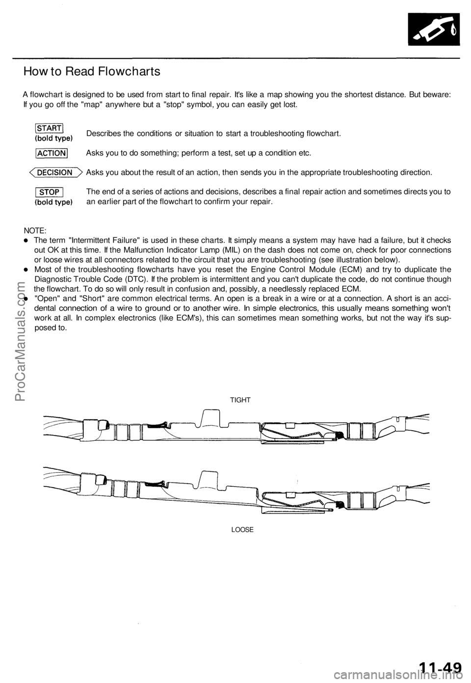
A flowchart is designed to be used from start to final repair. It's like a map showing you the shortest distance. But beware:
If you go off the "map" anywhere but a "stop" symbol, you can easily get lost.
Describes the conditions or situation to start a troubleshooting flowchart.
Asks you to do something; perform a test, set up a condition etc.
Asks you about the result of an action, then sends you in the appropriate troubleshooting direction.
The end of a series of actions and decisions, describes a final repair action and sometimes directs you to
an earlier part of the flowchart to confirm your repair.
NOTE:
The term "Intermittent Failure" is used in these charts. It simply means a system may have had a failure, but it checks
out OK at this time. If the Malfunction Indicator Lamp (MIL) on the dash does not come on, check for poor connections
or loose wires at all connectors related to the circuit that you are troubleshooting (see illustration below).
Most of the troubleshooting flowcharts have you reset the Engine Control Module (ECM) and try to duplicate the
Diagnostic Trouble Code (DTC). If the problem is intermittent and you can't duplicate the code, do not continue though
the flowchart. To do so will only result in confusion and, possibly, a needlessly replaced ECM.
"Open" and "Short" are common electrical terms. An open is a break in a wire or at a connection. A short is an acci-
dental connection of a wire to ground or to another wire. In simple electronics, this usually means something won't
work at all. In complex electronics (like ECM's), this can sometimes mean something works, but not the way it's sup-
posed to.
TIGHT
LOOSEProCarManuals.com
Page 877 of 1771
PGM-FI System
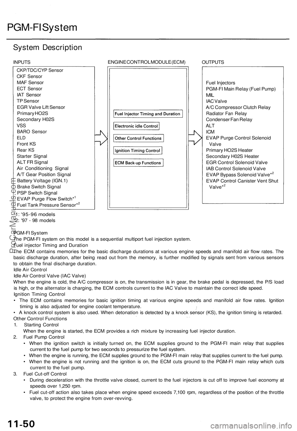
System Description
INPUTS
ENGINE CONTROL MODULE (ECM)
OUTPUTS
Fuel Injectors
PGM-FI Main Relay (Fuel Pump)
MIL
IAC Valve
A/C Compressor Clutch Relay
Radiator Fan Relay
Condenser Fan Relay
ALT
ICM
EVAP Purge Control Solenoid
Valve
Primary HO2S Heater
Secondary H02S Heater
EGR Control Solenoid Valve
IAB Control Solenoid Valve
EVAP Bypass Solenoid Valve*2
EVAP Control Canister Vent Shut
Valve*2
*1: '95-96 models
*2: '97 - 98 models
PGM-FI System
The PGM-FI system on this model is a sequential multiport fuel injection system.
Fuel injector Timing and Duration
The ECM contains memories for the basic discharge durations at various engine speeds and manifold air flow rates. The
basic discharge duration, after being read out from the memory, is further modified by signals sent from various sensors
to obtain the final discharge duration.
Idle Air Control
Idle Air Control Valve (IAC Valve)
When the engine is cold, the A/C compressor is on, the transmission is in gear, the brake pedal is depressed, the P/S load
is high, or the alternator is charging, the ECM controls current to the IAC Valve to maintain the correct idle speed.
Ignition Timing Control
• The ECM contains memories for basic ignition timing at various engine speeds and manifold air flow rates. Ignition
timing is also adjusted for engine coolant temperature.
• A knock control system is also used. When detonation is detected by a knock sensor (KS), the ignition timing is retarded.
Other Control Functions
1. Starting Control
When the engine is started, the ECM provides a rich mixture by increasing fuel injector duration.
2. Fuel Pump Control
• When the ignition switch is initially turned on, the ECM supplies ground to the PGM-FI main relay that supplies
current to the fuel pump for two seconds to pressurize the fuel system.
• When the engine is running, the ECM supplies ground to the PGM-FI main relay that supplies current to the fuel pump.
• When the engine is not running and the ignition is on, the ECM cuts ground to the PGM-FI main relay which cuts
current to the fuel pump.
3. Fuel Cut-off Control
• During deceleration with the throttle valve closed, current to the fuel injectors is cut off to improve fuel economy at
speeds over 1,250 rpm.
• Fuel cut-off action also takes place when engine speed exceeds 7,100 rpm, regardless of the position of the throttle
valve, to protect the engine from over-revving.
CKP/TDC/CYP Sensor
CKF Sensor
MAF Sensor
ECT Sensor
IAT Sensor
TP Sensor
EGR Valve Lift Sensor
Primary HO2S
Secondary H02S
VSS
BARO Sensor
ELD
Front KS
Rear KS
Starter Signal
ALT FR Signal
Air Conditioning Signal
A/T Gear Position Signal
Battery Voltage (IGN.1)
Brake Switch Signal
PSP Switch Signal
EVAP Purge Flow Switch*1
Fuel Tank Pressure Sensor*2ProCarManuals.com
Page 878 of 1771
4. A/ C Compresso r Clutc h Rela y
When th e EC M receive s a deman d fo r coolin g fro m th e ai r conditionin g system , i t delay s th e compresso r fro m bein g
energized , an d enriche s th e mixtur e to assur e smoot h transitio n to th e A/ C mode .
5 . Evaporativ e Emissio n (EVAP ) Purg e Contro l Solenoi d Valv e
Whe n th e engin e coolan t temperatur e i s belo w 167° F (75°C ) ('9 7 - 9 8 models : 158° F (70°C) , th e EC M control s th e
EVA P purg e contro l solenoi d valv e whic h cut s vacuu m to th e EVA P purg e contro l caniste r diaphragm .
6 . Intak e Ai r Bypas s (IAB ) Contro l Solenoi d Valv e
Whe n th e engin e spee d i s belo w 4,80 0 rpm , th e IA B contro l solenoi d valv e i s activate d b y a signa l fro m th e ECM ,
intak e ai r flow s throug h th e smalle r chamber , the n hig h torqu e i s delivered. At speed s highe r tha n 4,80 0 rpm , th e
solenoi d valv e i s deactivate d b y th e ECM , an d intak e ai r flow s throug h th e large r chambe r i n orde r t o reduc e th e
resistanc e in airflow .
7 . Exhaus t Ga s Recirculatio n (EGR ) Contro l Solenoi d Valv e
Whe n th e EG R is require d fo r contro l o f oxide s o f nitroge n (NOx ) emissions , th e EC M control s th e EG R contro l
solenoi d valv e whic h supplie s regulate d vacuu m to th e EG R valve .
8 . Alternato r Contro l
Th e syste m control s th e voltag e generate d a t th e alternato r i n accordanc e wit h th e electrica l loa d an d drivin g mode ,
whic h reduce s th e engin e loa d to improv e th e fue l economy .
ECM Fail-safe/Back-u p Function s
1. Fail-saf e Functio n
Whe n a n abnormalit y occur s in a signa l fro m a sensor , th e EC M ignore s tha t signa l an d assume s a pre-programme d
valu e fo r tha t senso r tha t allow s th e engin e to continu e to run .
2 . Back-u p Functio n
Whe n a n abnormalit y occur s in th e EC M itself , th e fue l injector s ar e controlle d b y a back-u p circui t independen t o f th e
syste m in orde r t o permi t minima l driving .
3 . Self-diagnosi s Functio n [Malfunctio n Indicato r Lam p (MIL) ]
Whe n a n abnormalit y occur s i n a signa l fro m a sensor , th e EC M supplie s groun d fo r th e MI L an d store s th e DT C in
erasable memory . Whe n th e ignitio n i s initiall y turne d on , th e EC M supplie s ground for th e MI L fo r tw o second s t o
chec k th e MI L bul b condition .
4 . Tw o Tri p Detectio n Metho d ('9 5 - 9 6 models )
T o preven t fals e indications , th e Tw o Tri p Detectio n Metho d is use d fo r th e MA F sensor , H02S , fue l metering-related ,
idl e contro l system , EC T sensor , an d EG R syste m self-diagnosti c functions . Whe n a n abnormalit y occurs , th e EC M
store s i t i n it s memory . Whe n th e sam e abnormalit y recur s afte r th e ignitio n switc h i s turne d OF F an d O N (II ) again ,
th e EC M inform s th e drive r b y lightin g th e MIL .
However ,
to eas e troubleshooting , thi s functio n is cancelle d when you shor t the servic e check connector . The MI L will
the n blin k immediatel y whe n a n abnormalit y occurs .
5 . Tw o (o r Three ) Drivin g Cycl e Detectio n Metho d ('9 5 - 9 6 models )
A "Drivin g Cycle " consist s o f startin g th e engine , beginnin g close d loo p operation , an d stoppin g th e engine . I f misfir -
in g tha t increase s emission s o r EVA P contro l syste m malfunctio n i s detecte d i n tw o consecutiv e drivin g cycles , o r
TW C deterioratio n is detecte d in thre e consecutiv e drivin g cycles , th e EC M turn s th e MI L on .
However , t o eas e troubleshooting , thi s functio n is cancelle d whe n yo u shor t th e servic e chec k connector . Th e MI L wil l
the n blin k immediatel y whe n a n abnormalit y occurs .
6 . Tw o Drivin g Cycl e Detectio n Metho d ('9 7 - 9 8 models )
T o preven t fals e indications , th e "tw o drivin g cycl e detectio n method " i s use d fo r th e H02S , fue l metering-related ,
idl e contro l system , EC T sensor , EG R system , TW C an d EVA P contro l syste m an d othe r self-diagnosti c functions .
Whe n a n abnormalit y occurs , th e EC M store s i t i n it s memory . Whe n th e sam e abnormalit y recur s afte r switc h i s
turne d OF F an d O N (II ) again , th e EC M inform s th e drive r b y turnin g o n th e MIL .
ProCarManuals.com