Page 728 of 1771
Engine Removal/Installatio n
Installation
Bracket Bolt s Torqu e Specifications :
ENGINE HANGE R
P/ S PUM P
BRACKE T
10 x 1.2 5 mm49 N- m (5. 0 kgf-m ,36 Ibf-ft )
ALTERNATO RBRACKET
10 x 1.2 5 mm49 N- m (5. 0 kgf-m ,
3 6 Ibf-ft )
RIGH T FRON T MOUN T
BRACKE T
10 x 1.2 5 mm44 N- m (4. 5 kgf-m ,33 Ibf-ft )
LEFT FRON T MOUN TBRACKE T
A/CCOMPRESSO RBRACKET
12 x 1.2 5 mm54 N- m (5. 5 kgf-m ,
4 0 Ibf-ft )
10 x 1.2 5 mm49 N- m (5. 0 kgf-m ,
3 6 Ibf-ft )
10 x 1.2 5 mm54 N- m (5. 5 kgf-m , 4 0 Ibf-ft )
8 x 1.2 5 mm22 N- m (2. 2 kgf-m ,
1 6 Ibf-ft )
10 x 1.2 5 mm54 N- m (5. 5 kgf-m , 4 0 Ibf-ft )
NOTE : Whe n installin g th e A/ C compresso r
bracket , tighte n th e bolt s o n th e oi l pa n
first , the n thos e o n th e cylinde r block .
8 x 1.2 5 mm34 N- m (3. 5 kgf-m , 2 5 Ibf-ft )
ProCarManuals.com
Page 729 of 1771

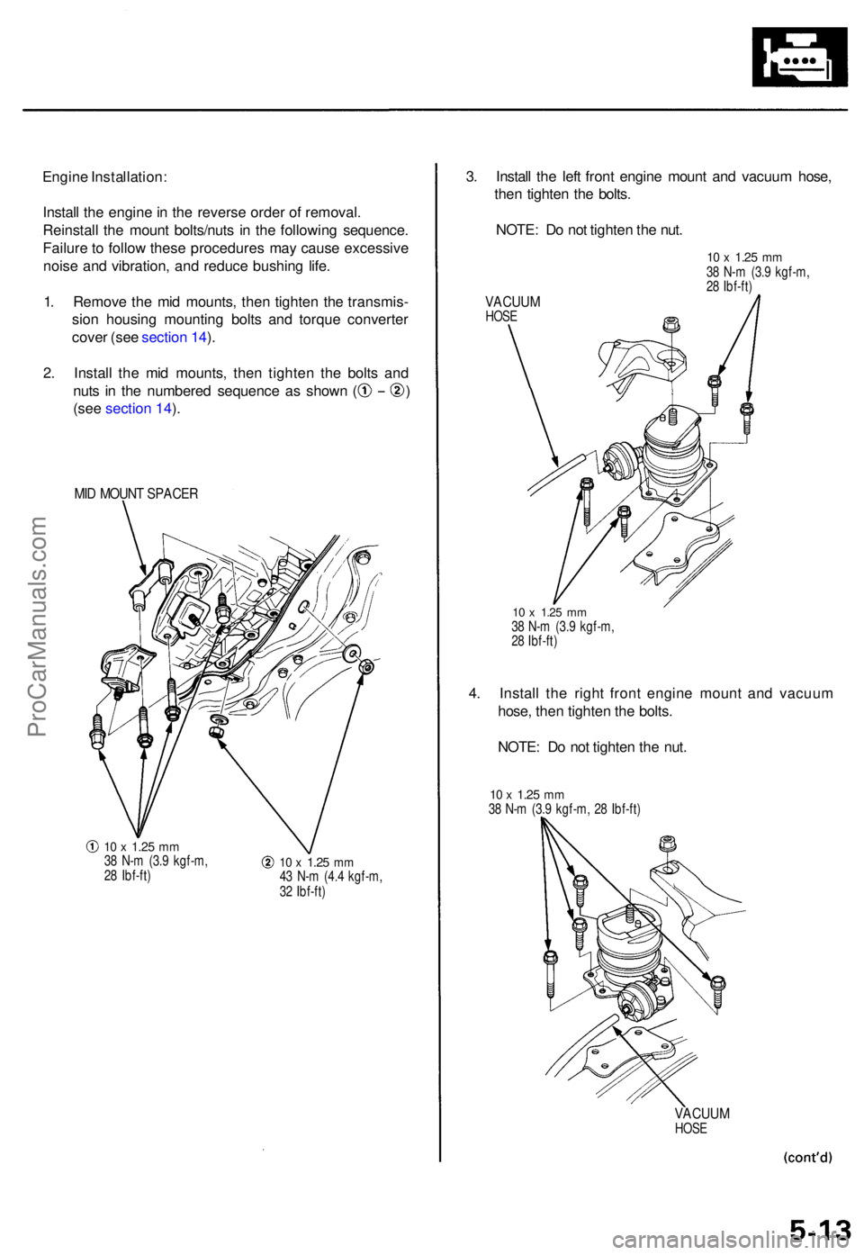
Engine Installation :
Instal l th e engin e in th e revers e orde r o f removal .
Reinstal l th e moun t bolts/nut s i n th e followin g sequence .
Failur e to follo w thes e procedure s ma y caus e excessiv e
nois e an d vibration , an d reduc e bushin g life .
1 . Remov e th e mi d mounts , the n tighte n th e transmis -
sio n housin g mountin g bolt s an d torqu e converte r
cove r (se e sectio n 14 ).
2 . Instal l th e mi d mounts , the n tighte n th e bolt s an d
nuts i n th e numbere d sequenc e a s show n ( )
(see section 14 ).
MID MOUN T SPACE R
10 x 1.2 5 mm38 N- m (3. 9 kgf-m ,
2 8 Ibf-ft )10 x 1.2 5 mm43 N- m (4. 4 kgf-m ,
3 2 Ibf-ft )
3. Instal l th e lef t fron t engin e moun t an d vacuu m hose ,
the n tighte n th e bolts .
NOTE : D o no t tighte n th e nut .
VACUU MHOSE
10 x 1.2 5 mm38 N- m (3. 9 kgf-m ,
2 8 Ibf-ft )
10 x 1.2 5 m m38 N- m (3. 9 kgf-m ,
2 8 Ibf-ft )
4. Instal l th e righ t fron t engin e moun t an d vacuu m
hose , the n tighte n th e bolts .
NOTE : D o no t tighte n th e nut .
10 x 1.2 5 mm38 N- m (3. 9 kgf-m , 2 8 Ibf-ft )
VACUU MHOSE
ProCarManuals.com
Page 730 of 1771
Engine Removal/Installatio n
Installation (cont'd )
5. Tighte n th e nu t o n th e lef t fron t engine mount.
12 x 1.2 5 mm74 N- m (7. 5 kgf-m ,54 Ibf-ft )
6. Tighte n th e nu t o n th e righ t fron t engin e mount .
12 x 1.2 5 mm74 N- m (7. 5 kgf-m , 5 4 Ibf-ft )
7. Instal l th e extensio n shaf t (se e sectio n 14 ).
8 . Instal l th e transmissio n moun t an d moun t bracket ,
the n tighte n th e bolt s i n th e numbere d sequenc e a s
show n ( ) .
12 x 1.2 5 mm54 N- m (5. 5 kgf-m ,
4 0 Ibf-ft )
12 x 1.2 5 mm54 N- m (5. 5 kgf-m ,
4 0 Ibf-ft )
12 x 1.2 5 mm64 N- m (6. 5 kgf-m ,47 Ibf-ft )Replace .
ProCarManuals.com
Page 732 of 1771
Engine Moun t Contro l Syste m
Componen t Locatio n Inde x
ENGIN E CONTRO L
MODUL E (ECM )
Troubleshooting , pag e 5-1 8
ENGINE MOUN T CONTRO L
SOLENOID VALV ETroubleshooting , pag e 5-1 8
FRON T ENGIN E MOUN T
DIAPHRAG M ACTUATO RTest, pag e 5-2 0
ProCarManuals.com
Page 733 of 1771

Engine Moun t Contro l Syste m
Troubleshootin g Flowchar t
NOTE:
• Chec k th e vacuu m hose s an d pipe s fo r damag e an d prope r connections .
• Refe r t o pag e 11-2 8 throug h 11-3 1 befor e troubleshooting .
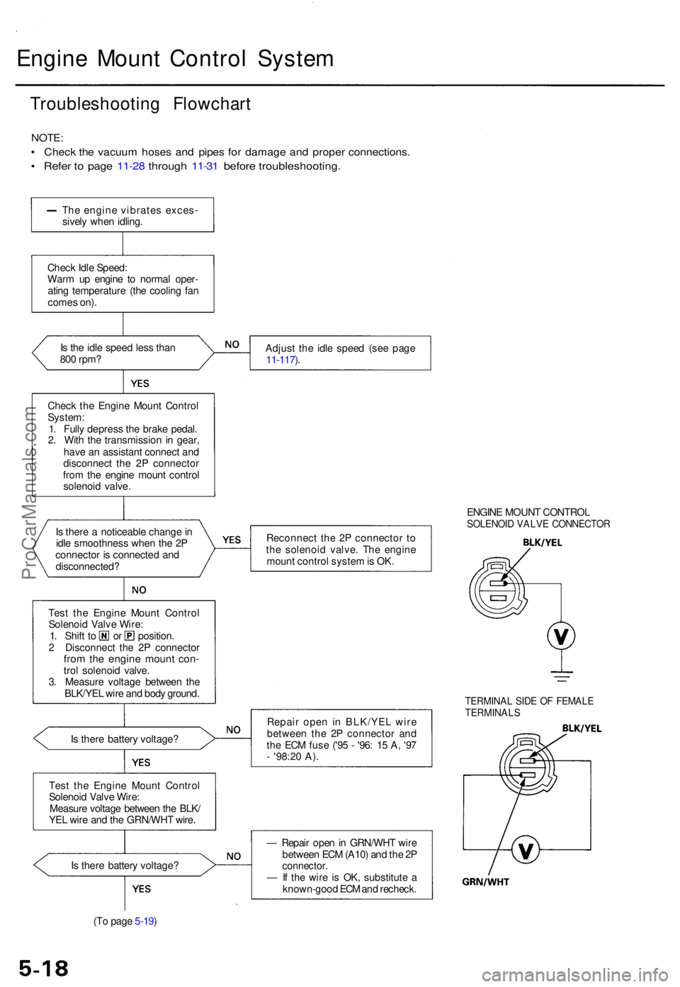
The engin e vibrate s exces -
sivel y whe n idling .
Chec k Idl e Speed :
War m u p engin e t o norma l oper -
atin g temperatur e (th e coolin g fa n
come s on) .
I s th e idl e spee d les s tha n
80 0 rpm ?
Chec k th e Engin e Moun t Contro l
System :
1 . Full y depres s th e brak e pedal .
2 . Wit h th e transmissio n i n gear ,
hav e a n assistan t connec t an d
disconnec t th e 2 P connecto r
fro m th e engin e moun t contro l
solenoi d valve .
I s ther e a noticeabl e chang e in
idl e smoothnes s whe n th e 2 P
connecto r i s connecte d an d
disconnected ?
Tes t th e Engin e Moun t Contro l
Solenoi d Valv e Wire :
1. Shif t t o o r position .
2 Disconnec t th e 2 P connecto r
from th e engin e moun t con -trol solenoi d valve .
3 . Measur e voltag e betwee n th e
BLK/YE L wir e an d bod y ground .
I s ther e batter y voltage ?
Tes t th e Engin e Moun t Contro l
Solenoi d Valv e Wire :
Measur e voltag e betwee n th e BLK /
YE L wir e an d th e GRN/WH T wire . Adjus
t th e idl e spee d (se e pag e
11-117 ).
Reconnec t th e 2 P connecto r t o
th e solenoi d valve . Th e engin e
moun t contro l syste m is OK . ENGIN
E MOUN T CONTRO L
SOLENOID VALV E CONNECTO R
Repair ope n i n BLK/YE L wir e
betwee n th e 2 P connecto r an d
th e EC M fus e ('9 5 - '96 : 1 5 A , '9 7
- '98:2 0 A) .
TERMINA L SID E O F FEMAL ETERMINAL S
Is ther e batter y voltage ?
(T o pag e 5-19 ) —
Repai r ope n in GRN/WH T wir e
betwee n EC M (A10 ) an d th e 2 Pconnector .— If th e wir e i s OK , substitut e a
known-goo d EC M an d recheck .
ProCarManuals.com
Page 734 of 1771

(From pag e 5-18 )
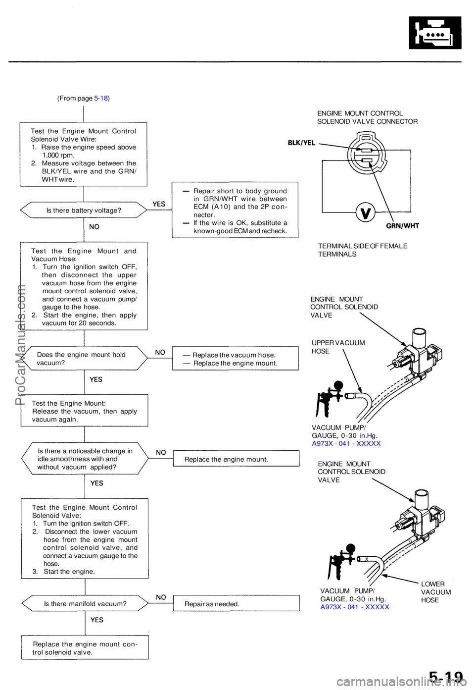
Tes t th e Engin e Moun t Contro l
Solenoi d Valv e Wire :
1 . Rais e th e engin e spee d abov e
1,000 rpm .2. Measur e voltag e betwee n th e
BLK/YE L wir e an d th e GRN /
WHT wire .
ENGIN E MOUN T CONTRO LSOLENOID VALV E CONNECTO R
Is ther e batter y voltage ?
Tes t th e Engin e Moun t an d
Vacuu m Hose :
1 . Tur n th e ignitio n switc h OFF ,
the n disconnec t th e uppe r
vacuu m hos e fro m th e engin e
moun t contro l solenoi d valve ,
an d connec t a vacuu m pump /
gaug e t o th e hose .
2 . Star t th e engine , the n appl y
vacuu m fo r 2 0 seconds .
Doe s th e engin e moun t hol d
vacuum ?
Test th e Engin e Mount :
Releas e th e vacuum , the n appl y
vacuu m again .
I s ther e a noticeabl e chang e in
idl e smoothnes s wit h an dwithou t vacuu m applied ?
Tes t th e Engin e Moun t Contro l
Solenoi d Valve :
1 . Tur n th e ignitio n switc h OFF .
2 . Disconnec t th e lowe r vacuu m
hos e fro m th e engin e moun t
contro l solenoi d valve , an d
connec t a vacuu m gaug e to th e
hose .3. Star t th e engine .
I s ther e manifol d vacuum ? Repai
r shor t t o bod y groun d
i n GRN/WH T wir e betwee n
ECM (A10 ) and th e 2 P con -nector .If th e wir e i s OK , substitut e a
known-goo d EC M an d recheck .
— Replac e th e vacuu m hose .
— Replac e th e engin e mount . TERMINA
L SID E O F FEMAL E
TERMINAL S
ENGINE MOUN TCONTRO L SOLENOI DVALVE
UPPER VACUU MHOSE
Replac e th e engin e mount . VACUU
M PUMP /
GAUGE , 0-3 0 in.Hg .
A973 X - 04 1 - XXXX X
ENGIN E MOUN T
CONTRO L SOLENOI D
VALVE
Repair a s needed . VACUU
M PUMP /
GAUGE , 0-3 0 in.Hg .
A973 X - 04 1 - XXXX X
LOWERVACUU MHOSE
Replac e th e engin e moun t con -
tro l solenoi d valve .
ProCarManuals.com
Page 735 of 1771
Diaphragm Actuato r Tes t
1. Disconnec t th e vacuu m hoses , the n remov e th e fron t
engin e mount s (se e pag e 5-11 ).
2 . Clea n an d oi l th e diaphrag m actuato r rod , roto r lever ,
an d leve r linkage .
3 . Wit h a vacuu m pump/gauge , appl y vacuu m o f abou t
30. 7 kP a (23 0 mmHg , 9. 1 in.Hg) , an d chec k i f th e
roto r leve r turn s 8 0 degrees .
— Replac e th e fron t engin e moun t i f th e roto r leve r
doe s no t operate .
FRONT ENGIN EMOUNTDIAPHRAG MACTUATOR
ROTORLEVER
VACUU M PUMP /GAUGE , 0-3 0 in.Hg .
A973 X - 04 1 - XXXX X
Engine Moun t Contro l Syste m
ProCarManuals.com
Page 750 of 1771

Cylinder Hea d
Remova l
Engine remova l i s no t require d fo r thi s procedure .
Mak e sur e jack s an d safet y stand s ar e
place d properl y an d hois t bracket s ar e attache d to cor -
rec t positio n o n th e engine .
CAUTION :
• Us e fende r cover s t o avoi d damagin g painte d sur -
faces .
• Unplu g th e wirin g connector s carefull y whil e holdin g
th e connecto r portio n to avoi d damage .
• T o avoi d damagin g th e cylinde r head , wai t unti l th e
engin e coolan t temperatur e drop s belo w 100° F
(38°C ) befor e loosenin g th e retainin g bolts .
NOTE :
• Mar k al l wirin g an d hose s t o avoi d misconnection .
Also , b e sur e tha t the y d o no t contac t othe r wirin g o r
hoses , o r interfer e wit h othe r parts .
• Inspec t th e timin g bel t befor e removin g th e cylinde r
head .
• Tur n th e crankshaf t pulle y s o tha t th e No . 1 pisto n i s
a t to p dea d cente r (se e pag e 6-12 ).
1 . Mak e sur e yo u hav e th e anti-thef t cod e fo r th e radio ,
the n writ e dow n th e frequencie s fo r th e radio' s pre -
se t buttons .
2 . Disconnec t th e negativ e termina l fro m th e battery .
3 . Drai n th e engin e coolan t (se e pag e 10-5 ).
Remov e th e radiato r cap to spee d draining .
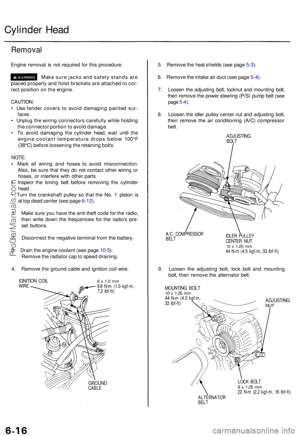
4 . Remov e th e groun d cabl e an d ignitio n coi l wire .
IGNITIO N COI LWIRE6 x 1. 0 m m9.8 N- m (1. 0 kgf-m ,
7. 2 Ibf-ft )
GROUN DCABLE
5. Remov e th e hea t shield s (se e pag e 5-3 ).
6 . Remov e th e intak e ai r duc t (se e pag e 5-4 ).
7 . Loose n th e adjustin g bolt , locknu t an d mountin g bolt ,
the n remov e th e powe r steerin g (P/S ) pum p bel t (se e
page 5-4 ).
8 . Loose n th e idle r pulle y cente r nu t an d adjustin g bolt ,
the n remov e th e ai r conditionin g (A/C ) compresso r
belt .
ADJUSTIN GBOLT
A/ C COMPRESSO R
BELTIDLE R PULLE YCENTER NU T10 x 1.2 5 mm44 N- m (4. 5 kgf-m , 3 3 Ibf-ft )
9. Loose n th e adjustin g bolt , loc k bol t an d mountin g
bolt , the n remov e th e alternato r belt .
MOUNTIN G BOL T10 x 1.2 5 mm44 N- m (4. 5 kgf-m ,
3 3 Ibf-ft )ADJUSTIN GNUT
LOC K BOL T8 x 1.2 5 mm22 N- m (2. 2 kgf-m , 1 6 Ibf-ft )
ALTERNATO R
BELT
ProCarManuals.com