Page 691 of 1771
Engine Bloc k — Sectio n 7
Engin e Lubricatio n — Sectio n 8
ProCarManuals.com
Page 719 of 1771
Engine Removal/Installation
Removal
• Make sure jacks and safety stands are placed properly
and hoist brackets are attached to the correct positions
on the engine.
• Make sure the car will not roll off stands and fall
while you are working under it.
CAUTION:
• Use fender covers to avoid damaging painted sur-
face.
• Unplug the wiring connectors carefully while holding
the connector portion to avoid damage.
• Mark all wiring and hoses to avoid misconnection.
Also, be sure that they do not contact other wiring
or hoses or interfere with other parts.
1. Secure the hood open as far as possible.
2. Make sure you have the anti-theft code for the radio,
then write down the frequencies for the radio's pre-
set buttons.
3. Disconnect the battery negative terminal first, then
the positive terminal.
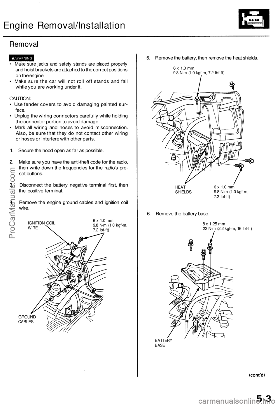
4. Remove the engine ground cables and ignition coil
wire.
IGNITION COIL
WIRE
GROUND
CABLES
6 x 1.0 mm
9.8 N-m (1.0 kgf-m,
7.2 Ibf-ft)
5. Remove the battery, then remove the heat shields.
6 x 1.0 mm
9.8 N-m (1.0 kgf-m, 7.2 Ibf-ft)
HEAT
SHIELDS
6. Remove the battery base.
6 x 1.0 mm
9.8 N-m (1.0 kgf-m,
7.2 Ibf-ft)
8 x
1.25
mm
22 N-m (2.2 kgf-m, 16 Ibf-ft)
BATTERY
BASEProCarManuals.com
Page 720 of 1771
Engine Removal/Installation
Removal (cont'd)
7. Remove the battery cables from the under-hood fuse/
relay box.
BATTERY
CABLES
8.
9.
UNDER-HOOD
FUSE/RELAY BOX
Disconnect the engine wire harness connector on
the right (passenger's) side of the engine compart-
ment.
Remove the battery cable from the under-hood ABS
fuse/relay box.
BATTERY
CABLE
ENGINE WIRE
HARNESS
UNDER-HOOD ABS
FUSE/RELAY BOX
10. Remove the intake air duct and vacuum hose.
INTAKE AIR
DUCT
11.
VACUUM
HOSE
Remove the adjusting bolt, locknut and mounting
bolt, then remove the power steering (P/S) pump
belt and pump.
MOUNTING BOLT
10 x
1.25
mm
49 N-m (5.0 kgf-m, 36 Ibf-ft)
ADJUSTING
BOLT
P/S PUMP
BELT
LOCKNUT
8 x
1.25
mm
22 N-m (2.2 kgf-m,
16 Ibf-ft)ProCarManuals.com
Page 721 of 1771
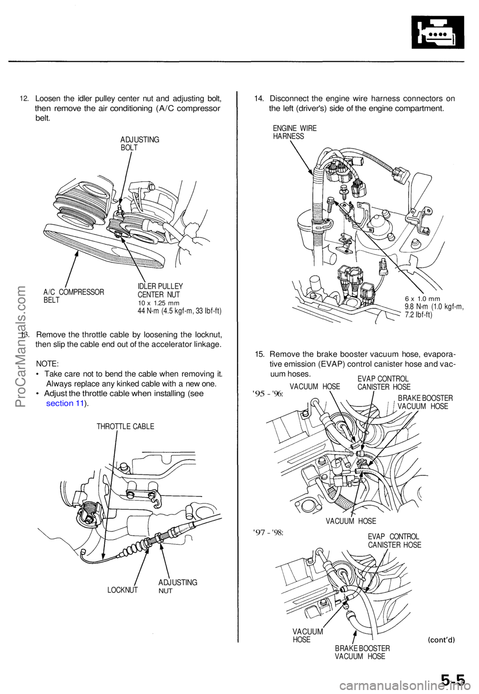
12.Loose n th e idle r pulle y cente r nu t an d adjustin g bolt ,
then remov e th e ai r conditionin g (A/ C compresso r
belt.
ADJUSTIN GBOLT
A/ C COMPRESSO R
BELT
IDLE R PULLE Y
CENTE R NU T
10 x 1.2 5 mm44 N- m (4.5 kgf-m , 3 3 Ibf-ft )
13.Remov e th e throttl e cabl e b y loosenin g th e locknut ,
the n sli p th e cabl e en d ou t o f th e accelerato r linkage .
NOTE:
• Tak e car e no t t o ben d th e cabl e whe n removin g it .
Alway s replac e an y kinke d cabl e wit h a ne w one .
• Adjus t th e throttl e cabl e whe n installin g (se e
sectio n 11 ).
THROTTL E CABL E
LOCKNU T
ADJUSTIN GNUT
14. Disconnec t th e engin e wir e harnes s connector s o n
the lef t (driver's ) sid e o f th e engin e compartment .
ENGINE WIR E
HARNES S
6 x 1. 0 m m9.8 N- m (1. 0 kgf-m ,
7. 2 Ibf-ft )
15. Remov e th e brak e booste r vacuu m hose , evapora -
tiv e emissio n (EVAP ) contro l caniste r hos e an d vac -
uu m hoses .
'95 - '96 :VACUU M HOS E EVA
P CONTRO L
CANISTE R HOS E
BRAK E BOOSTE R
VACUU M HOS E
VACUU M HOS E
'97 - '98 :EVA P CONTRO L
CANISTE R HOS E
VACUU MHOSE
BRAKE BOOSTE R
VACUU M HOS E
ProCarManuals.com
Page 722 of 1771
Engine Removal/Installatio n
Removal (cont'd )
16. Reliev e fue l pressur e (se e sectio n 11 ).
D o no t smok e whil e workin g o n th e fue l system .
Kee p ope n flam e o r spark s awa y fro m th e wor k
area . Drai n fue l onl y int o a n approve d container .
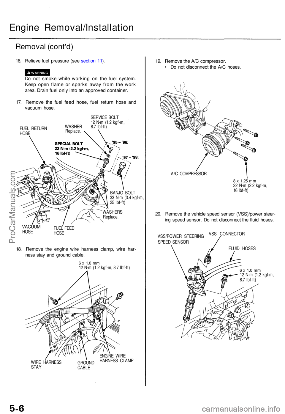
17 . Remov e th e fue l fee d hose , fue l retur n hos e an d
vacuu m hose .
FUEL RETUR N
HOS E SERVIC
E BOL T
1 2 N- m (1. 2 kgf-m ,
WASHE R 8. 7 Ibf-ft )
Replace .
BANJO BOL T
3 3 N- m (3. 4 kgf-m ,
2 5 Ibf-ft )
WASHER S
Replace .
VACUUMHOSE FUE
L FEE D
HOS E
18. Remov e th e engin e wir e harnes s clamp , wir e har -
nes s sta y an d groun d cable .
6 x 1. 0 m m12 N- m (1.2 kgf-m , 8. 7 Ibf-ft )
WIR E HARNES S
STA Y GROUN
D
CABLE
ENGIN E WIR E
HARNES S CLAM P
19. Remov e th e A/ C compressor .
• D o no t disconnec t th e A/ C hoses .
A/C COMPRESSO R
8 x 1.2 5 mm22 N- m (2. 2 kgf-m ,
1 6 Ibf-ft )
20. Remov e th e vehicl e spee d senso r (VSS)/powe r steer -
in g spee d sensor . D o no t disconnec t th e flui d hoses .
VSS/POWE R STEERIN G
SPEE D SENSO R VS
S CONNECTO R
FLUI D HOSE S
6 x 1. 0 m m12 N- m (1. 2 kgf-m ,
8. 7 Ibf-ft )
ProCarManuals.com
Page 724 of 1771
Engine Removal/Installatio n
Removal (cont'd )
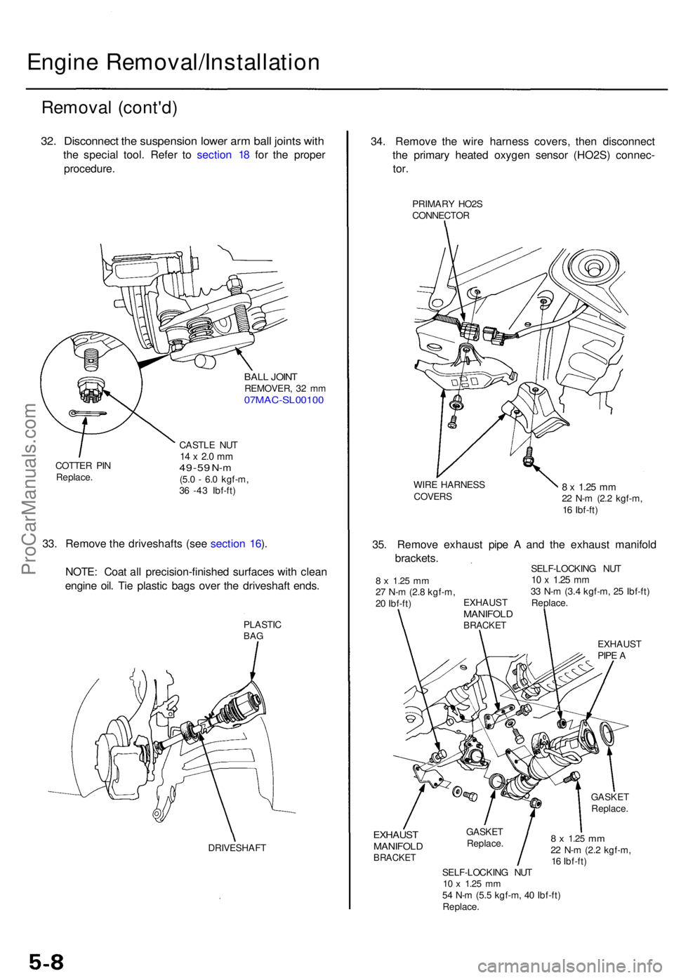
32. Disconnec t th e suspensio n lowe r ar m bal l joint s wit h
the specia l tool . Refe r t o sectio n 1 8 fo r th e prope r
procedure .
BALL JOIN TREMOVER , 3 2 m m07MAC-SL0010 0
COTTER PI N
Replace . CASTL
E NU T14 x 2. 0 m m49-5 9 N-m(5.0 - 6. 0 kgf-m ,
3 6 -4 3 Ibf-ft )
33. Remov e th e driveshaft s (se e sectio n 16 ).
NOTE : Coa t al l precision-finishe d surface s wit h clea n
engin e oil . Ti e plasti c bag s ove r th e driveshaf t ends .
PLASTI CBAG
DRIVESHAF T
34. Remov e th e wir e harnes s covers , the n disconnec t
th e primar y heate d oxyge n senso r (HO2S ) connec -
tor.
PRIMAR Y HO2 S
CONNECTO R
WIR E HARNES S
COVERS8 x 1.2 5 m m22 N- m (2. 2 kgf-m ,
1 6 Ibf-ft )
EXHAUS TMANIFOL DBRACKET
GASKETReplace .
8 x 1.2 5 mm22 N- m (2. 2 kgf-m ,
1 6 Ibf-ft )
SELF-LOCKIN G NU T
10 x 1.2 5 mm54 N- m (5. 5 kgf-m , 4 0 Ibf-ft )
Replace .
GASKE
T
Replace .
35. Remov e exhaus t pip e A an d th e exhaus t manifol d
brackets .
SELF-LOCKIN G NU T10 x 1.2 5 mm33 N- m (3. 4 kgf-m , 2 5 Ibf-ft )
Replace .
EXHAUS T
PIP E A
EXHAUS
T
MANIFOL DBRACKET
8 x 1.2 5 mm27 N- m (2. 8 kgf-m ,
2 0 Ibf-ft )
ProCarManuals.com
Page 726 of 1771
Engine Removal/Installation
Removal (cont'd)
43. Attach the chain hoist to the engine.ProCarManuals.com
Page 727 of 1771
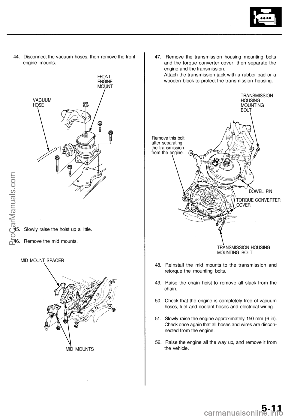
44. Disconnect the vacuum hoses, then remove the front
engine mounts.
VACUUM
HOSE
FRONT
ENGINE
MOUNT
45. Slowly raise the hoist up a little.
46. Remove the mid mounts.
MID MOUNT SPACER
MID MOUNTS
47. Remove the transmission housing mounting bolts
and the torque converter cover, then separate the
engine and the transmission.
Attach the transmission jack with a rubber pad or a
wooden block to protect the transmission housing.
Remove this bolt
after separating
the transmission
from the engine.
TRANSMISSION
HOUSING
MOUNTING
BOLT
DOWEL PIN
TORQUE CONVERTER
COVER
TRANSMISSION HOUSING
MOUNTING BOLT
48. Reinstall the mid mounts to the transmission and
retorque the mounting bolts.
49. Raise the chain hoist to remove all slack from the
chain.
50. Check that the engine is completely free of vacuum
hoses, fuel and coolant hoses and electrical wiring.
51. Slowly raise the engine approximately 150 mm (6 in).
Check once again that all hoses and wires are discon-
nected from the engine.
52. Raise the engine all the way up, and remove it from
the vehicle.ProCarManuals.com