1995 ACURA TL engine
[x] Cancel search: enginePage 522 of 1771
Troubleshooting Precautions
ABS Indicator Light
1. If the system is OK, the ABS indicator light goes off two seconds after turning the ignition switch ON (II) without start-
ing the engine. After starting the engine, the ABS indicator light comes on again and goes off after two seconds. This
occurs because the ABS control unit is activated by the IG2 power source.
2. The ABS indicator light comes on when the ABS control unit detects a problem in the system. However, even though
the system is normal, the ABS indicator light comes on, too, under the following conditions. To determine the actual
cause of problem, question the customer about the problem, talking the following conditions into consideration.
Only drive wheels rotate
One wheel stuck of drive wheels
Vehicle spin
ABS operate condition continue for long time
Signal disturbance
3. When a problem is detected and the ABS indicator light comes on, there are cases when the indicator light stays on
until the ignition switch is turned OFF, and cases when the indicator light goes off automatically when the system
returns normal. For the DTC 61 and 62, the indicator light goes off automatically when the system returns normal. For
all other codes, the indicator light stays on until the ignition switch is turned OFF.
4. For DTCs 12, 14, 16, 18, 21, 22, 23, 24, 51, 52 and 53, the indicator light goes off when the vehicle is driven again and
the signals are OK after the ignition switch is turned from OFF to ON (II). However, if the DTC is erased, the CPU is
reset and the indicator light goes off right after the engine is started if the signals are OK.
Diagnostic Trouble Code (DTC)
1. The DTC is not memorized if the CPU cannot be activated or the CPU fails and the indicator light comes on.
2. The memory can hold any number of DTCs. However, when the same DTC is detected more than once, the later one
is written over the old one. Therefore, when the same problem is detected repeatedly, it is memorized as one DTC.
3. The DTCs are indicated in the order of ascending number, not in the order they occur.
4. The DTCs are memorized in the EEPROM (non-volatile memory). Therefore, the memorized DTCs cannot be canceled
by disconnecting the battery. Perform the specified procedures to erase the DTCs.
Self-diagnosis
1. The
self-diagnosis
can be
classified
into
two
categories.
• Initial diagnosis: Performed right after the engine starts and until the ABS indicator light goes off.
• Regular diagnosis: Performed right after the initial diagnosis until the ignition switch is turned OFF.
2. When a problem is detected by self-diagnosis, the system
• Turns the ABS indicator light ON
• Memorizes the DTC
• Turns the fail-safe relay OFF
• Stops ABS controlProCarManuals.com
Page 529 of 1771
System Descriptio n
Outline
Role o f Syste m
Th e tractio n contro l i s a variabl e syste m designe d t o enhanc e tractio n durin g acceleratio n an d cornering . I t doe s s o b y
determinin g th e optimu m amoun t o f whee l spi n fo r an y give n drivin g situation , the n suppressin g surplu s engin e powe r
accordingly .
Constructio n an d Functio n
The TC S contro l uni t get s signal s abou t th e vehicle' s speed , direction , an d roa d condition s fro m sensor s a t th e wheel s an d
the steerin g column . Base d o n thes e signals , th e contro l uni t wil l determin e th e optimu m amoun t o f whee l spin . Becaus e
th e syste m is variable , th e contro l uni t ma y determine , dependin g o n th e drivin g conditions , tha t som e whee l spi n i s bene -
ficia l (thu s enhancin g straight-lin e acceleration) , o r tha t n o whee l spi n i s beneficia l (thu s enhancin g cornering) . Fo r an y
give n drivin g situation , th e contro l uni t wil l determin e th e amoun t o f whee l spi n bes t suite d t o th e driver' s need s and , i f
necessary , wil l the n signa l th e TC S contro l valv e actuato r an d Powertrai n Contro l Modul e (PCM ) t o reduc e engin e power .
Th e syste m is automaticall y "ready " wheneve r th e engine is started , bu t ca n b e manuall y cancele d wit h th e TC S switch .
However , onc e activated , th e syste m canno t b e cancele d unti l i t i s onc e agai n i n th e read y state .
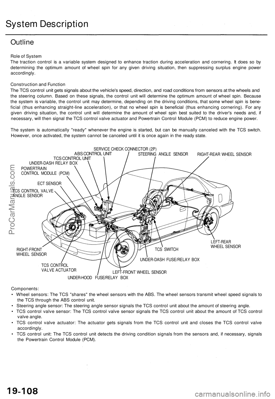
SERVIC E CHEC K CONNECTO R (2P )ABS CONTRO L UNI TTCS CONTRO L UNI TUNDER-DAS H RELA Y BO X
POWERTRAI N
CONTRO L MODUL E (PCM )
EC T SENSO R
TC S CONTRO L VALV E
ANGL E SENSO R STEERIN
G ANGL E SENSO R
RIGHT-REA R WHEE L SENSO R
RIGHT-FRON T
WHEE L SENSO R
Components :
• Whee l sensors : Th e TC S "shares " th e whee l sensor s wit h th e ABS . Th e whee l sensor s transmi t whee l spee d signal s t o
th e TC S throug h th e AB S contro l unit .
• Steerin g angl e sensor : Th e steerin g angl e senso r signal s th e TC S contro l uni t abou t th e amoun t o f steerin g angle .
• TC S contro l valv e sensor : Th e TC S contro l valv e senso r signal s th e TC S contro l uni t abou t th e amoun t o f TC S contro l
valv e angle .
• TC S contro l valv e actuator : Th e actuato r get s signal s fro m th e TC S contro l uni t an d close s th e TC S contro l valv e
accordingly .
• TC S contro l unit : Th e TC S contro l uni t detect s th e drivin g conditio n signal s fro m th e sensor s and , i f necessary , signal s
th e Powertrai n Contro l Modul e (PCM) .
LEFT-REA RWHEEL SENSO R
UNDER-HOO D FUSE/RELA Y BO X
LEFT-FRON
T WHEE L SENSO R
TC
S CONTRO L
VALV E ACTUATO R UNDER-DAS
H FUSE/RELA Y BO X
TC
S SWITC H
ProCarManuals.com
Page 530 of 1771
Construction and Function
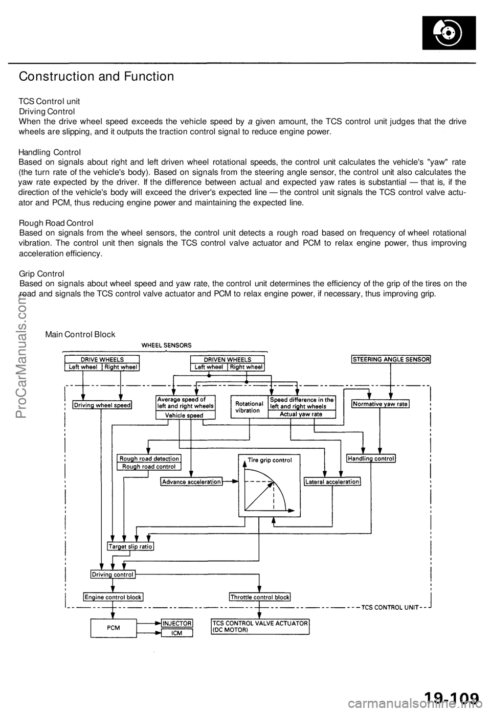
TCS Control unit
Driving Control
When the drive wheel speed exceeds the vehicle speed by a given amount, the TCS control unit judges that the drive
wheels are slipping, and it outputs the traction control signal to reduce engine power.
Handling Control
Based on signals about right and left driven wheel rotational speeds, the control unit calculates the vehicle's "yaw" rate
(the turn rate of the vehicle's body). Based on signals from the steering angle sensor, the control unit also calculates the
yaw rate expected by the driver. If the difference between actual and expected yaw rates is substantial — that is, if the
direction of the vehicle's body will exceed the driver's expected line — the control unit signals the TCS control valve actu-
ator and PCM, thus reducing engine power and maintaining the expected line.
Rough Road Control
Based on signals from the wheel sensors, the control unit detects a rough road based on frequency of wheel rotational
vibration. The control unit then signals the TCS control valve actuator and PCM to relax engine power, thus improving
acceleration efficiency.
Grip Control
Based on signals about wheel speed and yaw rate, the control unit determines the efficiency of the grip of the tires on the
road and signals the TCS control valve actuator and PCM to relax engine power, if necessary, thus improving grip.
Main Control BlockProCarManuals.com
Page 532 of 1771
Engine Outpu t Contro l
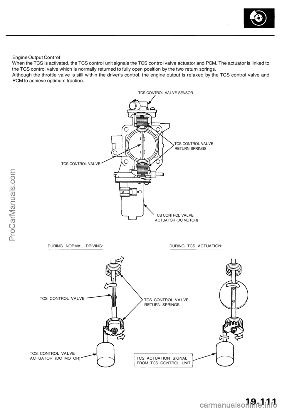
Whe n th e TC S is activated , th e TC S contro l uni t signal s th e TC S contro l valv e actuato r an d PCM . Th e actuato r i s linke d to
th e TC S contro l valv e whic h is normall y returne d to full y ope n positio n b y th e tw o retur n springs .
Althoug h th e throttl e valv e is stil l withi n th e driver' s control , th e engin e outpu t i s relaxe d b y th e TC S contro l valv e an d
PC M to achiev e optimu m traction .
TCS CONTRO L VALV E SENSO R
TCS CONTRO L VALV E
TCS CONTRO L VALV ERETUR N SPRING S
TCS CONTRO L VALV EACTUATO R (D C MOTOR )
DURING NORMA L DRIVING : DURING TC S ACTUATION :
TC S CONTRO L VALV E
TC S CONTRO L VALV E
ACTUATO R (D C MOTOR ) TC
S CONTRO L VALV E
RETUR N SPRING S
TC S ACTUATIO N SIGNA L
FRO M TC S CONTRO L UNI T
ProCarManuals.com
Page 536 of 1771
Diagnostic Troubl e Cod e (DTC )
Diagnosti c Troubl e Cod e (DTC ) Indicatio n
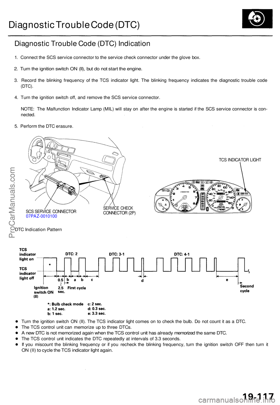
1. Connec t th e SC S servic e connecto r t o th e servic e chec k connecto r unde r th e glov e box .
2. Tur n th e ignitio n switc h O N (II) , bu t d o no t star t th e engine .
3. Recor d th e blinkin g frequenc y o f th e TC S indicato r light . Th e blinkin g frequenc y indicate s th e diagnosti c troubl e cod e
(DTC) .
4. Tur n th e ignitio n switc h off , an d remov e th e SC S servic e connector .
NOTE : Th e Malfunctio n Indicato r Lam p (MIL ) wil l sta y o n afte r th e engin e is starte d i f th e SC S servic e connecto r i s con -
nected .
5 . Perfor m th e DT C erasure .
SCS SERVIC E CONNECTO R07PAZ-001010 0
TCS INDICATO R LIGH T
SERVIC E CHEC KCONNECTO R (2P )
DTC Indicatio n Patter n
Tur n th e ignitio n switc h O N (II) . Th e TC S indicato r ligh t come s o n t o chec k th e bulb . D o no t coun t i t a s a DTC .
Th e TC S contro l uni t ca n memoriz e u p to thre e DTCs .
A ne w DT C is no t memorize d agai n whe n th e TC S contro l uni t ha s alread y memorize d th e sam e DTC .
The TC S contro l uni t indicate s th e DT C repeatedl y a t interval s o f 3. 3 seconds .
I f yo u miscoun t th e blinkin g frequenc y o r i f yo u rechec k th e blinkin g frequency , tur n th e ignitio n switc h OF F the n tur n i t
O N (II ) t o cycl e th e TC S indicato r ligh t again .
ProCarManuals.com
Page 539 of 1771
Electronic Component s
Steering Angl e Senso r Replacemen t
CAUTION: D o no t damag e o r dro p th e steerin g angl e senso r a s it i s sensitive .
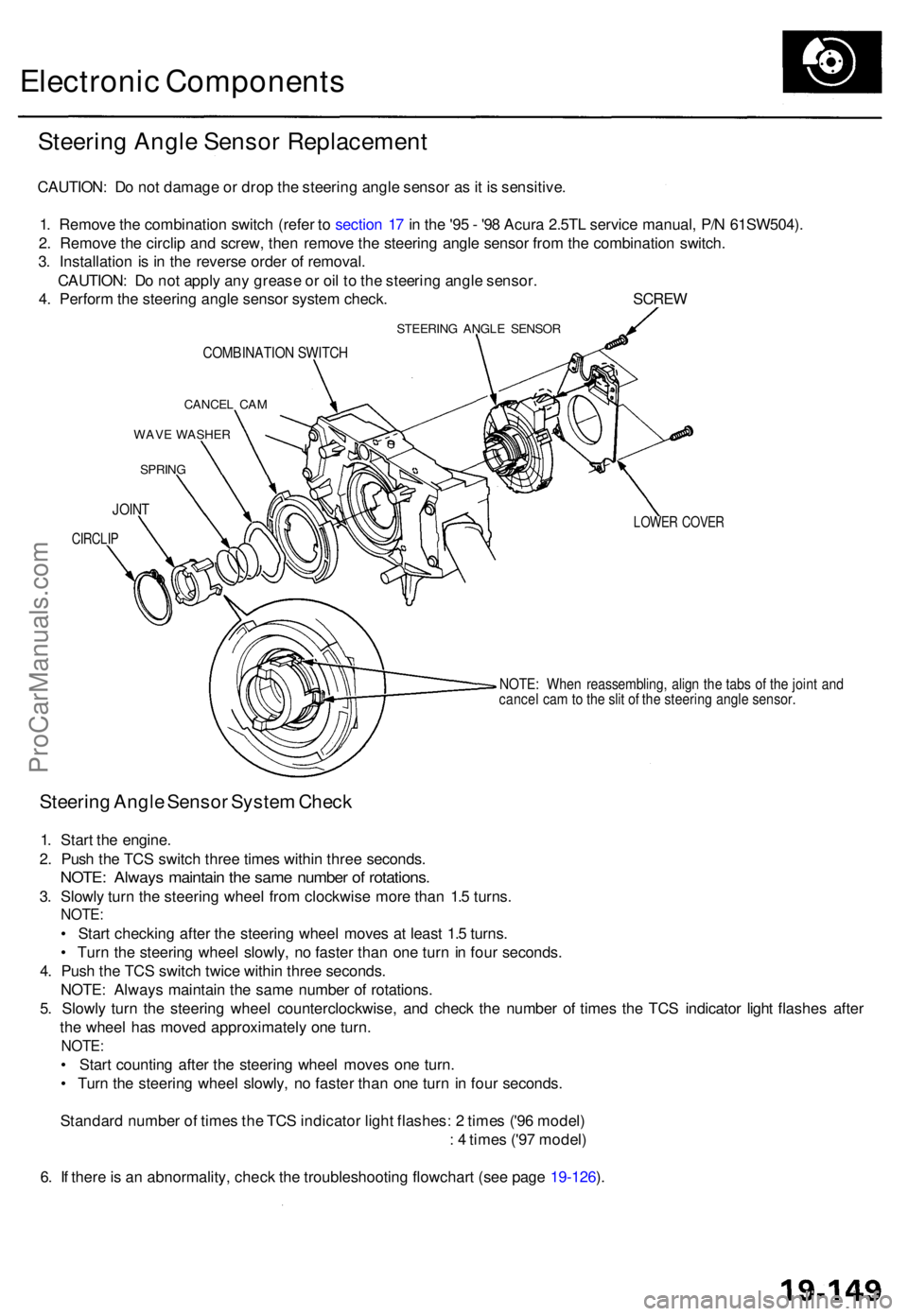
1 . Remov e th e combinatio n switc h (refe r t o sectio n 1 7 in th e '9 5 - '9 8 Acur a 2.5T L servic e manual , P/ N 61SW504) .
2 . Remov e th e circli p an d screw , the n remov e th e steerin g angl e senso r fro m th e combinatio n switch .
3 . Installatio n i s i n th e revers e orde r o f removal .
CAUTION : D o no t appl y an y greas e o r oi l t o th e steerin g angl e sensor .
4 . Perfor m th e steerin g angl e senso r syste m check . SCRE W
STEERING ANGL E SENSO R
COMBINATIO N SWITC H
CANCE L CA M
WAV E WASHE R
SPRING
LOWER COVE R
NOTE: Whe n reassembling , alig n th e tab s o f th e join t an d
cance l ca m to th e sli t o f th e steerin g angl e sensor .
Steering Angl e Senso r Syste m Chec k
1. Star t th e engine .
2 . Pus h th e TC S switc h thre e time s withi n thre e seconds .
NOTE: Alway s maintai n th e sam e numbe r o f rotations .
3. Slowl y tur n th e steerin g whee l fro m clockwis e mor e tha n 1. 5 turns .
NOTE :
• Star t checkin g afte r th e steerin g whee l move s a t leas t 1. 5 turns .
• Tur n th e steerin g whee l slowly , n o faste r tha n on e tur n in fou r seconds .
4 . Pus h th e TC S switc h twic e withi n thre e seconds .
NOTE : Alway s maintai n th e sam e numbe r o f rotations .
5 . Slowl y tur n th e steerin g whee l counterclockwise , an d chec k th e numbe r o f time s th e TC S indicato r ligh t flashe s afte r
th e whee l ha s move d approximatel y on e turn .
NOTE :
• Star t countin g afte r th e steerin g whee l move s on e turn .
• Tur n th e steerin g whee l slowly , n o faste r tha n on e tur n i n fou r seconds .
Standar d numbe r o f time s th e TC S indicato r ligh t flashes : 2 time s ('9 6 model )
: 4 time s ('9 7 model )
6 . I f ther e is a n abnormality , chec k th e troubleshooting flowchart (se e pag e 19-126 ).
JOIN T
CIRCLI P
ProCarManuals.com
Page 562 of 1771
Troubleshooting
Radiator Fan Control Module Input Tests
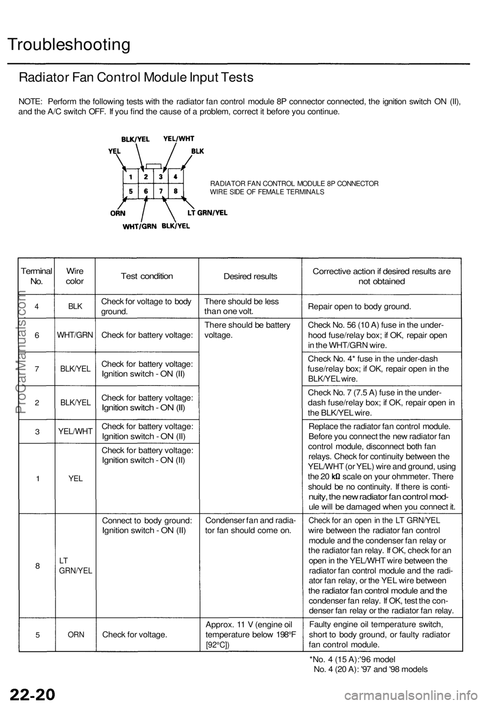
NOTE: Perform the following tests with the radiator fan control module 8P connector connected, the ignition switch ON (II),
and the A/C switch OFF. If you find the cause of a problem, correct it before you continue.
RADIATOR FAN CONTROL MODULE 8P CONNECTOR
WIRE SIDE OF FEMALE TERMINALS
Terminal
No.
4
6
7
2
3
1
8
5
Wire
color
BLK
WHT/GRN
BLK/YEL
BLK/YEL
YEL/WHT
YEL
LT
GRN/YEL
ORN
Test condition
Check for voltage to body
ground.
Check for battery voltage:
Check for battery voltage:
Ignition switch - ON (II)
Check for battery voltage:
Ignition switch - ON (II)
Check for battery voltage:
Ignition switch - ON (II)
Check for battery voltage:
Ignition switch - ON (II)
Connect to body ground:
Ignition switch - ON (II)
Check for voltage.
Desired results
There should be less
than one volt.
There should be battery
voltage.
Condenser fan and radia-
tor fan should come on.
Approx. 11 V (engine oil
temperature below 198°F
[92°C])
Corrective action if desired results are
not obtained
Repair open to body ground.
Check No. 56 (10 A) fuse in the under-
hood fuse/relay box; if OK, repair open
in the WHT/GRN wire.
Check No. 4* fuse in the under-dash
fuse/relay box; if OK, repair open in the
BLK/YEL wire.
Check No. 7 (7.5 A) fuse in the under-
dash fuse/relay box; if OK, repair open in
the BLK/YEL wire.
Replace the radiator fan control module.
Before you connect the new radiator fan
control module, disconnect both fan
relays. Check for continuity between the
YEL/WHT (or YEL) wire and ground, using
the 20 scale on your ohmmeter. There
should be no continuity. If there is conti-
nuity, the new radiator fan control mod-
ule will be damaged when you connect it.
Check for an open in the LT GRN/YEL
wire between the radiator fan control
module and the condenser fan relay or
the radiator fan relay. If OK, check for an
open in the YEL/WHT wire between the
radiator fan control module and the radi-
ator fan relay, or the YEL wire between
the radiator fan control module and the
condenser fan relay. If OK, test the con-
denser fan relay or the radiator fan relay.
Faulty engine oil temperature switch,
short to body ground, or faulty radiator
fan control module.
*No. 4 (15 A):'96 model
No. 4 (20 A): '97 and '98 modelsProCarManuals.com
Page 570 of 1771
A/C System Service
Performance Test
The performance test will help determine if the air con-
ditioner system is operating within specifications.
Use only service equipment that is U.L.-listed and is cer-
tified to meet the requirements of SAE J2210 to remove
HFC-134a (R-134a) from the air conditioner system.
CAUTION: Exposure to air conditioner refrigerant and
lubricant vapor or mist can irritate eyes, nose and
throat. Avoid breathing the air conditioner refrigerant
and lubricant vapor or mist.
If accidental system discharge occurs, ventilate work
area before resuming service.
R-134a service equipment or vehicle air conditioner sys-
tems should not be pressure tested or leak tested with
compressed air.
Some mixtures of air and R-134a have been
shown to be combustible at elevated pressures and can
result in fire or explosion causing injury or property
damage. Never use compressed air to pressure test R-
134a service equipment or vehicle air conditioner sys-
tems.
Additional health and safety information may be obtained
from the refrigerant and lubricant manufacturers.
1.
2.
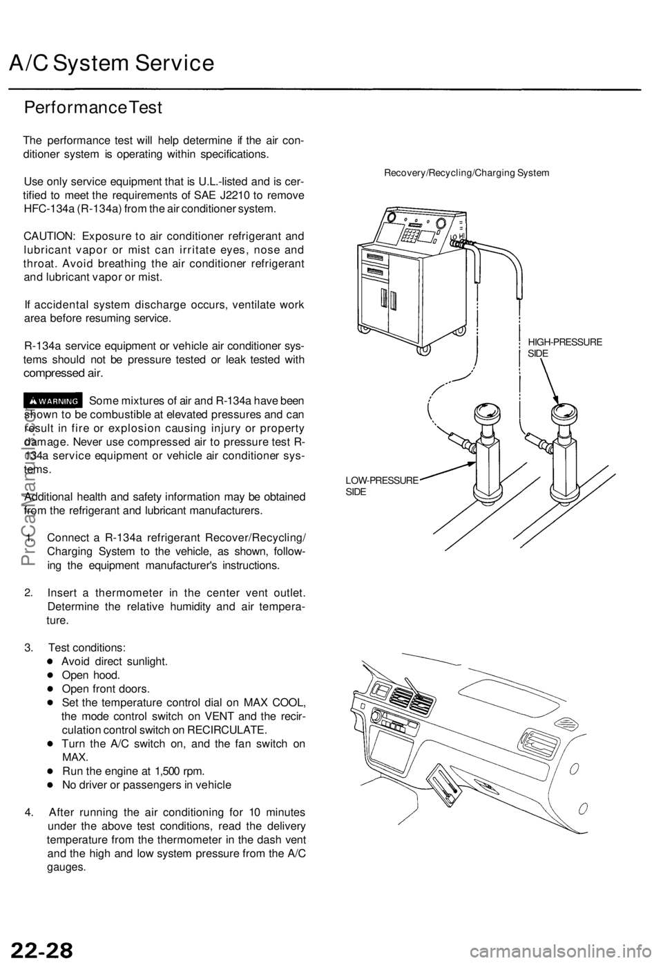
Connect a R-134a refrigerant Recover/Recycling/
Charging System to the vehicle, as shown, follow-
ing the equipment manufacturer's instructions.
Insert a thermometer in the center vent outlet.
Determine the relative humidity and air tempera-
ture.
Recovery/Recycling/Charging System
HIGH-PRESSURE
SIDE
LOW-PRESSURE
SIDE
3. Test conditions:
Avoid direct sunlight.
Open hood.
Open front doors.
Set the temperature control dial on MAX COOL,
the mode control switch on VENT and the recir-
culation control switch on RECIRCULATE.
Turn the A/C switch on, and the fan switch on
MAX.
Run the engine at 1,500 rpm.
No driver or passengers in vehicle
4. After running the air conditioning for 10 minutes
under the above test conditions, read the delivery
temperature from the thermometer in the dash vent
and the high and low system pressure from the A/C
gauges.ProCarManuals.com