Page 267 of 1771
Position
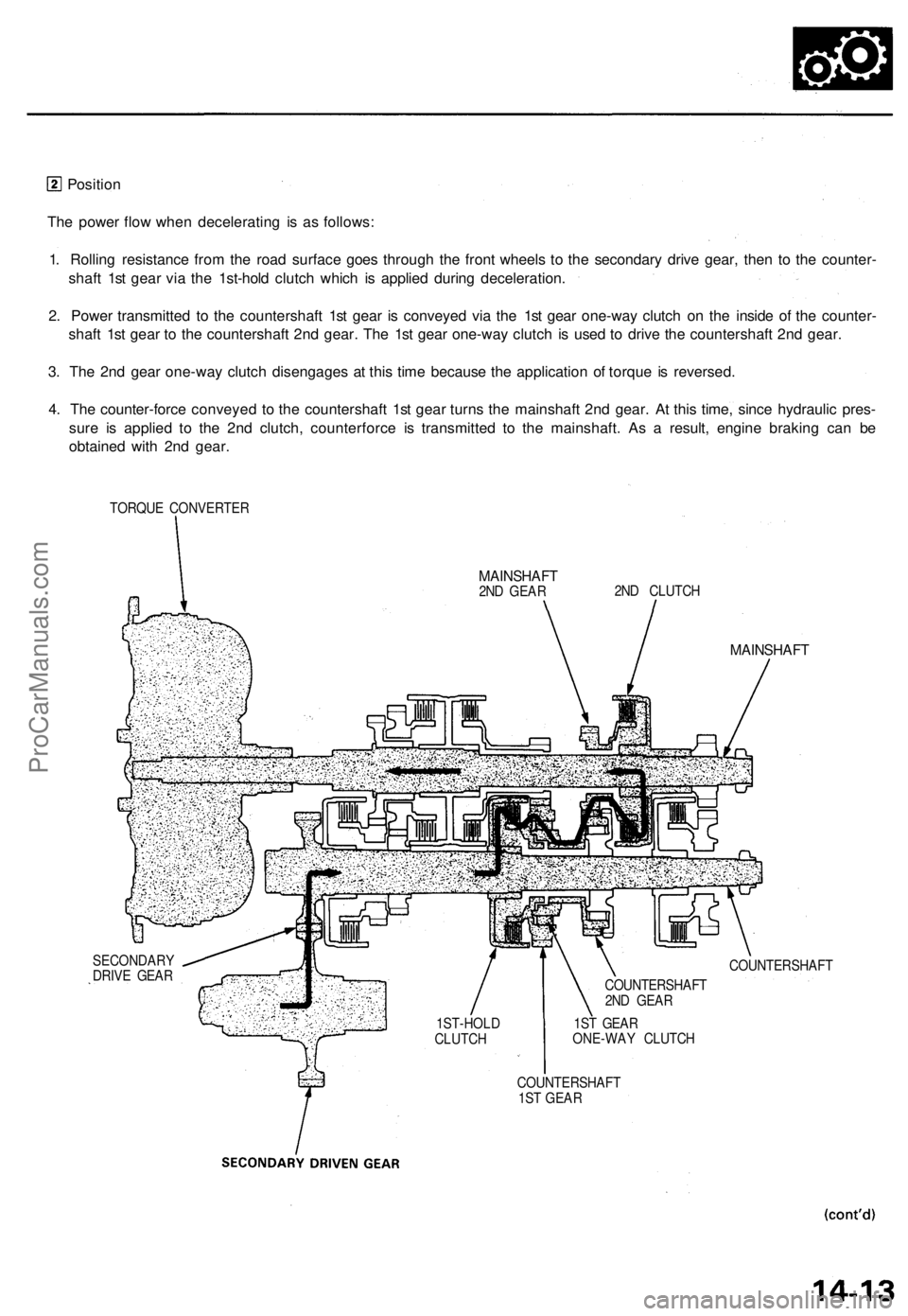
The power flow when decelerating is as follows:
1. Rolling resistance from the road surface goes through the front wheels to the secondary drive gear, then to the counter-
shaft 1st gear via the 1st-hold clutch which is applied during deceleration.
2. Power transmitted to the countershaft 1st gear is conveyed via the 1st gear one-way clutch on the inside of the counter-
shaft 1st gear to the countershaft 2nd gear. The 1st gear one-way clutch is used to drive the countershaft 2nd gear.
3. The 2nd gear one-way clutch disengages at this time because the application of torque is reversed.
4. The counter-force conveyed to the countershaft 1st gear turns the mainshaft 2nd gear. At this time, since hydraulic pres-
sure is applied to the 2nd clutch, counterforce is transmitted to the mainshaft. As a result, engine braking can be
obtained with 2nd gear.
TORQUE CONVERTER
MAINSHAFT
2ND GEAR
2ND CLUTCH
MAINSHAFT
COUNTERSHAFT
SECONDARY
DRIVE GEAR
1ST-HOLD
CLUTCH
COUNTERSHAFT
1ST GEAR
1ST GEAR
ONE-WAY CLUTCH
COUNTERSHAFT
2ND GEARProCarManuals.com
Page 268 of 1771
Description
Power Flow (cont'd)
1. The hydraulic pressure is applied to the 1st clutch, which rotates together with the mainshaft, and the mainshaft 1st
gear rotates.
2. Power is transmitted to the countershaft 1st gear, which drives the countershaft via the one-way clutches.
3. Power is transmitted to the secondary drive gear, which drives the secondary driven gear.
Position, 1st gear
position, the optimum gear is automatically selected from 1st, 2nd, 3rd, and 4th gears, according to conditions
balance between throttle opening (engine load) and vehicle speed.
or
such as the
or
In
TORQUE CONVERTER
SECONDARY
DRIVE GEAR
SECONDARY DRIVEN
GEAR
COUNTERSHAFT
1ST GEAR
1ST GEAR
ONE-WAY
CLUTCH
2ND GEAR
ONE-WAY CLUTCH
PARKING GEAR
COUNTERSHAFT
MAINSHAFT
1ST CLUTCH
MAINSHAFT
1ST GEAR
NOTE: In
position, hydraulic pressure is not applied to the 1st-hold clutch.
orProCarManuals.com
Page 275 of 1771
Grade Logic Control System
How it works:
The PCM compares actual driving conditions with driving conditions memorized in the PCM, based on the input from the
vehicle speed sensor, throttle position sensor, engine coolant temperature sensor, barometric pressure sensor, brake
switch signal and shift lever position signal, to control shifting while a vehicle is ascending or descending a slope, or
reducing speed.
(cont'd)ProCarManuals.com
Page 277 of 1771
Description
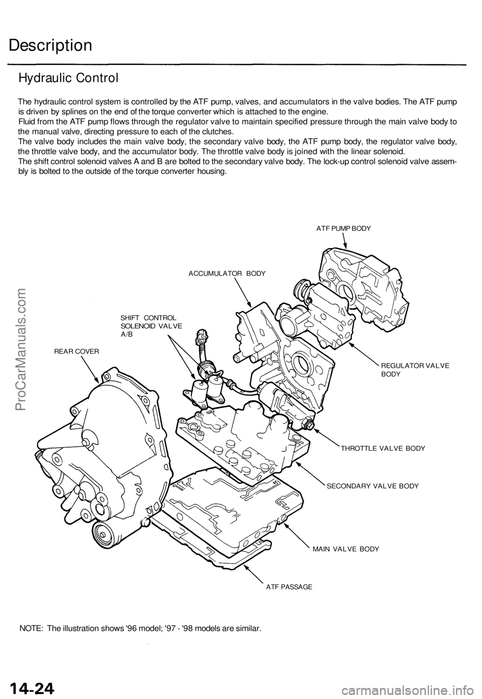
The hydraulic control system is controlled by the ATF pump, valves, and accumulators in the valve bodies. The ATF pump
is driven by splines on the end of the torque converter which is attached to the engine.
Fluid from the ATF pump flows through the regulator valve to maintain specified pressure through the main valve body to
the manual valve, directing pressure to each of the clutches.
The valve body includes the main valve body, the secondary valve body, the ATF pump body, the regulator valve body,
the throttle valve body, and the accumulator body. The throttle valve body is joined with the linear solenoid.
The shift control solenoid valves A and B are bolted to the secondary valve body. The lock-up control solenoid valve assem-
bly is bolted to the outside of the torque converter housing.
ATF PUMP BODY
ACCUMULATOR BODY
SHIFT CONTROL
SOLENOID VALVE
A/B
REAR COVER
REGULATOR VALVE
BODY
THROTTLE VALVE BODY
SECONDARY VALVE BODY
MAIN VALVE BODY
ATF PASSAGE
NOTE: The illustration shows '96 model; '97 - '98 models are similar.
Hydraulic ControlProCarManuals.com
Page 281 of 1771
Description
Regulator Valv e — '9 6 Mode l
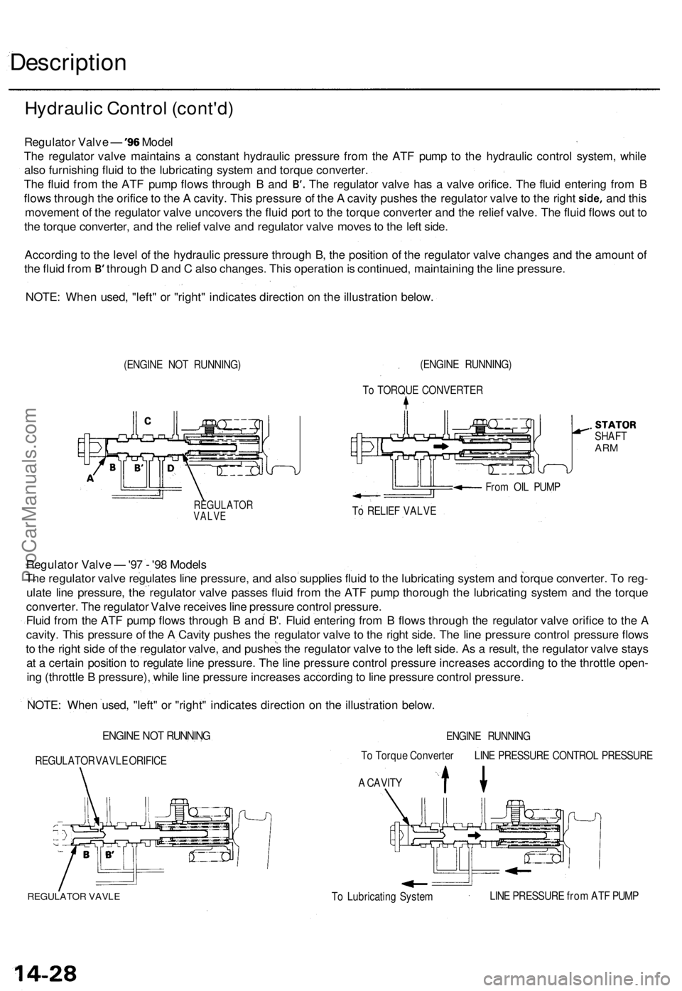
Th e regulato r valv e maintain s a constan t hydrauli c pressur e fro m th e AT F pum p t o th e hydrauli c contro l system , whil e
als o furnishin g flui d t o th e lubricatin g syste m an d torqu e converter .
The flui d fro m th e AT F pum p flow s throug h B an d B'. Th e regulato r valv e ha s a valv e orifice . Th e flui d enterin g fro m B
flow s throug h th e orific e to th e A cavity . Thi s pressur e o f th e A cavit y pushe s th e regulato r valv e to th e righ t side , and thi s
movemen t o f th e regulato r valv e uncover s th e flui d por t t o th e torqu e converte r an d th e relie f valve . Th e flui d flow s ou t t o
th e torqu e converter , an d th e relie f valv e an d regulato r valv e move s to th e lef t side .
Accordin g to th e leve l o f th e hydrauli c pressur e throug h B , th e positio n o f th e regulato r valv e change s an d th e amoun t o f
th e flui d fro m B' throug h D an d C als o changes . Thi s operatio n is continued , maintainin g th e lin e pressure .
NOTE : Whe n used , "left " o r "right " indicate s directio n o n th e illustratio n below .
(ENGIN E NO T RUNNING )
.STATORSHAFTARM
Fro m OI L PUM P
REGULATO RVALVETo RELIE F VALV E
Regulato r Valv e — '9 7 - '98 Model s
Th e regulato r valv e regulate s lin e pressure , an d als o supplie s flui d to th e lubricatin g syste m an d torqu e converter . T o reg -
ulat e lin e pressure ,
the regulato r valv e passe s flui d fro m th e AT F pum p thoroug h th e lubricatin g syste m an d th e torqu e
converter . Th e regulato r Valv e receive s lin e pressur e contro l pressure .
Flui d fro m th e AT F pum p flow s throug h B an d
B'. Flui d enterin g fro m B flow s throug h th e regulato r valv e orific e t o th e A
cavity . Thi s pressur e o f th e A Cavit y pushe s th e regulato r valv e t o th e righ t side . Th e lin e pressur e contro l pressur e flow s
t o th e righ t sid e o f th e regulato r valve , an d pushe s th e regulato r valv e to th e lef t side . A s a result , th e regulato r valv e stay s
a t a certai n positio n to regulat e lin e pressure . Th e lin e pressur e contro l pressur e increase s accordin g t o th e throttl e open -
in g (throttl e B pressure) , whil e lin e pressur e increase s
accordin g to lin e pressur e contro l pressure .
NOTE : Whe n used , "left " o r "right " indicate s directio n o n th e illustratio n below .
ENGINE NO T RUNNIN G
REGULATO R VAVL E ORIFIC E ENGIN
E RUNNIN G
T o Torqu e Converte r LIN E PRESSUR E CONTRO L PRESSUR E
A CAVIT Y
REGULATO R VAVL ETo Lubricatin g Syste m LIN
E PRESSUR E fro m AT F PUM P
Hydrauli c Contro l (cont'd )
(ENGINE RUNNING )
T o TORQU E CONVERTE R
ProCarManuals.com
Page 284 of 1771
Position
(cont'd)
As the engine turns, the ATF pump also starts to operate. Automatic transmission fluid (ATF) is drawn from (99) and dis-
charged into (1). Then, ATF flowing from the ATF pump becomes the line pressure (1). The line pressure (1) is regulated
by the regulator valve. The torque converter inlet pressure (92) enters (94) of the torque converter through the lock-up
shift valve and discharges into (90).
The torque converter check valve prevents the torque converter pressure from rising.
Under this condition, the hydraulic pressure is not applied to the clutches as the manual valve stops line pressure (1).
NOTE: When used, "left" or "right" indicates direction on the hydraulic circuit.ProCarManuals.com
Page 287 of 1771
Description
Hydraulic Flow — '96 Model (cont'd)
or
Position
NOTE: When used, "left" or "right" indicates direction on the hydraulic circuit.
1. 1st Gear
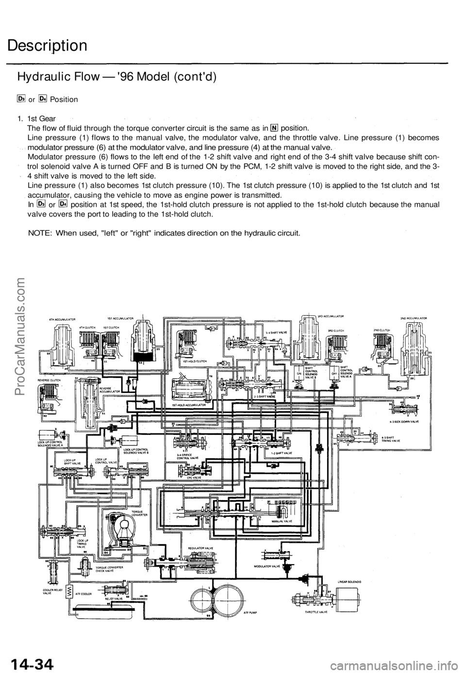
Line pressure (1) flows to the manual valve, the modulator valve, and the throttle valve. Line pressure (1) becomes
modulator pressure (6) at the modulator valve, and line pressure (4) at the manual valve.
Modulator pressure (6) flows to the left end of the 1-2 shift valve and right end of the 3-4 shift valve because shift con-
trol solenoid valve A is turned OFF and B is turned ON by the PCM, 1-2 shift valve is moved to the right side, and the 3-
4 shift valve is moved to the left side.
Line pressure (1) also becomes 1st clutch pressure (10). The 1st clutch pressure (10) is applied to the 1st clutch and 1st
accumulator, causing the vehicle to move as engine power is transmitted.
valve covers the port to leading to the 1st-hold clutch.
position.
The flow of fluid through the torque converter circuit is the same as in
In
or
position at 1st speed, the 1st-hold clutch pressure is not applied to the 1st-hold clutch because the manualProCarManuals.com
Page 293 of 1771
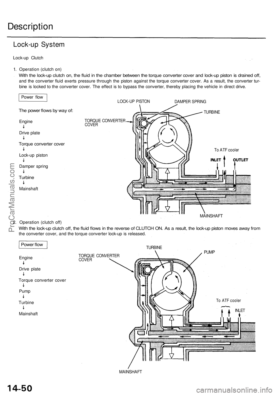
Description
Lock-up System
Lock-up Clutch
1. Operation (clutch on)
With the lock-up clutch on, the fluid in the chamber between the torque converter cover and lock-up piston is drained off,
and the converter fluid exerts pressure through the piston against the torque converter cover. As a result, the converter tur-
bine is locked to the converter cover. The effect is to bypass the converter, thereby placing the vehicle in direct drive.
LOCK-UP PISTON
TORQUE CONVERTER
COVER
TURBINE
DAMPER SPRING
To ATF cooler
TURBINE
PUMP
To ATF cooler
INLET
TORQUE CONVERTER
COVER
2. Operation (clutch off)
With the lock-up clutch off, the fluid flows in the reverse of CLUTCH ON. As a result, the lock-up piston moves away from
the converter cover, and the torque converter lock-up is released.
MAINSHAFT
Power flow
The power flows by way of:
Engine
Drive plate
Torque converter cover
Lock-up piston
Damper spring
Turbine
Mainshaft
Power flow
Engine
Drive plate
Torque converter cover
Pump
Turbine
Mainshaft
MAINSHAFTProCarManuals.com