1995 ACURA TL engine
[x] Cancel search: enginePage 236 of 1771
Fuel Suppl y Syste m
PGM-F I Mai n Rela y (cont'd )
Troubleshootin g Flowchar t
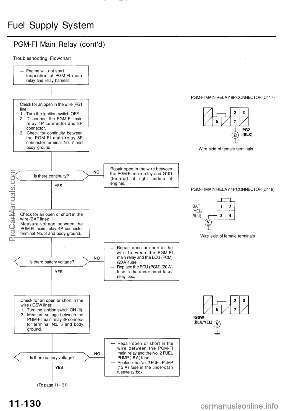
Engine wil l no t start .Inspectio n o f PGM-F I mai nrelay an d rela y harness .
Check fo r a n ope n in th e wir e (PG 1line) :1. Tur n th e ignitio n switc h OFF .
2 . Disconnec t th e PGM-F I mai n
rela y 4 P connecto r an d 8 P
connector .3. Chec k fo r continuit y betwee n
th e PGM-F I mai n rela y 8 P
connecto r termina l No . 7 an d
bod y ground . PGM-F
I MAI N RELA Y 8P CONNECTO R (C417 )
Wir e sid e o f femal e terminal s
I s ther e continuity ? Repai
r ope n in th e wir e betwee n
th e PGM-F I mai n rela y an d G10 1
(locate d a t righ t middl e o f
engine) .
Check fo r a n ope n o r shor t i n th e
wir e (BA T line) :
Measur e voltag e betwee n th e
PGM-F I mai n rela y 4 P connecto r
termina l No . 3 an d bod y ground . PGM-F
I MAI N RELA Y 4P CONNECTO R (C418 )
BAT(YEL /BLU)
Wire sid e o f femal e terminal s
I s ther e batter y voltage ? Repai
r ope n o r shor t i n th e
wir e betwee n th e PGM-F I
mai n rela y an d th e EC U (PCM )
(2 0 A ) fuse .
Replac e th e EC U (PCM ) (2 0 A )
fus e in th e under-hoo d fuse /
relay box .
Chec k fo r a n ope n o r shor t i n th e
wir e (IGS W line) :
1 . Tur n th e ignitio n switc h O N (II) .
2 . Measur e voltag e betwee n th e
PGM-F I mai n rela y 8 P connec -
to r termina l No . 5 an d bod y
ground .
Is ther e batter y voltage ?
(T o pag e 11-131 ) Repai
r ope n o r shor t i n th e
wir e betwee n th e PGM-F I
mai n rela y an d th e No . 2 FUE L
PUM P (1 5 A ) fuse .
Replac e th e No . 2 FUE L PUM P
(15 A ) fus e i n th e under-das hfuse/relay box .
ProCarManuals.com
Page 239 of 1771
Intake Air System
System Description
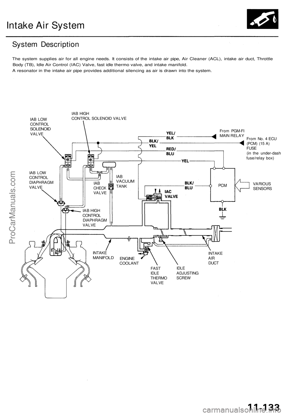
The system supplies air for all engine needs. It consists of the intake air pipe, Air Cleaner (ACL), intake air duct, Throttle
Body (TB), Idle Air Control (IAC) Valve, fast idle thermo valve, and intake manifold.
A resonator in the intake air pipe provides additional silencing as air is drawn into the system.
IAB LOW
CONTROL
SOLENOID
VALVE
IAB HIGH
CONTROL SOLENOID VALVE
IAB LOW
CONTROL
DIAPHRAGM
VALVE
From PGM-FI
MAIN RELAY
From No. 4 ECU
(PCM)
(15 A)
FUSE
(in the under-dash
fuse/relay box)
VARIOUS
SENSORS
INTAKE
AIR
DUCT
FAST
IDLE
THERMO
VALVE
IDLE
ADJUSTING
SCREW
ENGINE
COOLANT
INTAKE
MANIFOLD
PCM
IAB
VACUUM
TANK
IAB
CHECK
VALVE
IAB HIGH
CONTROL
DIAPHRAGM
VALVEProCarManuals.com
Page 241 of 1771
Throttle Cable
Inspection/Adjustment
1. Start the engine. Hold the engine at 3,000 rpm with
no load (transmission in or position) until the
radiator fan comes on, then let it idle.
2. Check that the throttle cable operates smoothly with
no binding or sticking. Repair as necessary.
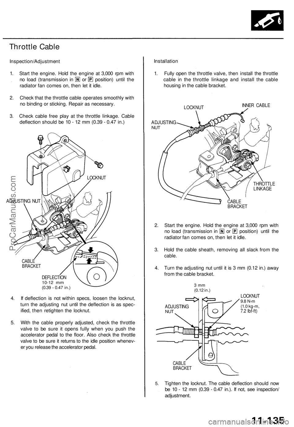
3. Check cable free play at the throttle linkage. Cable
deflection should be 10 - 12 mm (0.39 - 0.47 in.)
ADJUSTING NUT
CABLE
BRACKET
DEFLECTION
10-12
mm
(0.39
-
0.47 in.)
4. If deflection is not within specs, loosen the locknut,
turn the adjusting nut until the deflection is as spec-
ified, then retighten the locknut.
5. With the cable properly adjusted, check the throttle
valve to be sure it opens fully when you push the
accelerator pedal to the floor. Also check the throttle
valve to be sure it returns to the idle position whenev-
er you release the accelerator pedal.
Installation
1. Fully open the throttle valve, then install the throttle
cable in the throttle linkage and install the cable
housing in the cable bracket.
LOCKNUT
INNER CABLE
ADJUSTING
NUT
THROTTLE
LINKAGE
CABLE
BRACKET
2. Start the engine. Hold the engine at 3,000 rpm with
no load (transmission in or position) until the
radiator fan comes on, then let it idle.
3. Hold the cable sheath, removing all slack from the
cable.
4. Turn the adjusting nut until it is 3 mm (0.12 in.) away
from the cable bracket.
3 mm
(0.12 in.)
ADJUSTING
NUT
LOCKNUT
9.8 N-m
(1.0 kg-m,
7.2 Ibf-ft)
5.
CABLE
BRACKET
Tighten the locknut. The cable deflection should now
be 10 - 12 mm (0.39 - 0.47 in.). If not, see inspection/
adjustment.
LOCKNUTProCarManuals.com
Page 242 of 1771
Intake Ai r Syste m
Throttl e Bod y
Descriptio n
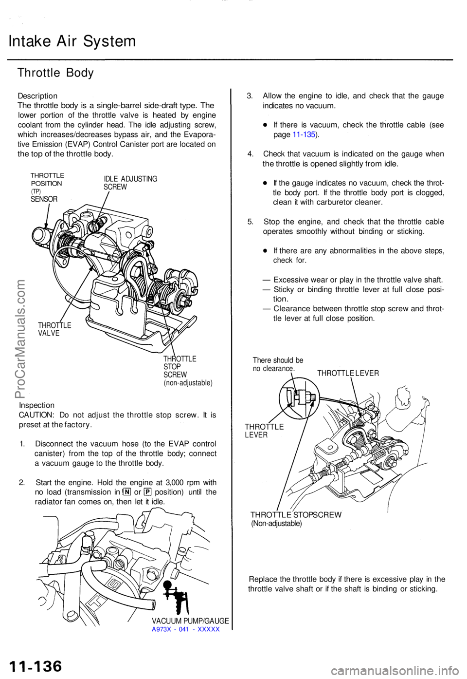
The throttl e bod y i s a single-barre l side-draf t type . Th e
lowe r portio n o f th e throttl e valv e i s heate d b y engin e
coolan t fro m th e cylinde r head . Th e idl e adjustin g screw ,
whic h increases/decrease s bypas s air , an d th e Evapora -
tiv e Emissio n (EVAP ) Contro l Caniste r por t ar e locate d o n
the to p o f th e throttl e body .
THROTTL EPOSITION(TP)SENSO R
IDLE ADJUSTIN GSCREW
THROTTL E
VALV E
THROTTLE
STOPSCRE W
(non-adjustable )
Inspection
CAUTION : D o no t adjus t th e throttl e sto p screw . I t i s
prese t a t th e factory .
1 . Disconnec t th e vacuu m hos e (t o th e EVA P contro l
canister ) fro m th e to p o f th e throttl e body ; connec t
a vacuu m gaug e t o th e throttl e body .
2 . Star t th e engine . Hol d th e engine at 3,00 0 rp m wit h
no loa d (transmissio n i n ! o r position ) unti l th e
radiato r fa n come s on , the n le t i t idle .
VACUU M PUMP/GAUG EA973X - 04 1 - XXXX X
3. Allo w th e engin e t o idle , an d chec k tha t th e gaug e
indicate s n o vacuum .
If ther e i s vacuum , chec k th e throttl e cabl e (se e
pag e 11-135 ).
4 . Chec k tha t vacuu m is indicate d o n th e gaug e whe n
the throttl e is opene d slightl y fro m idle .
If th e gaug e indicate s n o vacuum , chec k th e throt -
tl e bod y port . I f th e throttl e bod y por t i s clogged ,
clea n i t wit h carbureto r cleaner .
5 . Sto p th e engine , an d chec k tha t th e throttl e cabl e
operates smoothly without bindin g o r sticking .
I f ther e ar e an y abnormalitie s i n th e abov e steps ,
check for .
— Excessiv e wea r o r pla y i n th e throttl e valv e shaft .
— Stick y o r bindin g throttl e leve r a t ful l close posi-
tion.
— Clearanc e betwee n throttl e sto p scre w an d throt -
tl e leve r a t ful l clos e position .
There shoul d b eno clearance .THROTTLE LEVE R
THROTTL ELEVER
THROTTL E STO P SCRE W(Non-adjustable )
Replace th e throttl e bod y i f ther e is excessiv e pla y i n th e
throttl e valv e shaf t o r i f th e shaf t i s bindin g o r sticking .
ProCarManuals.com
Page 252 of 1771
Emission Control System
Positive Crankcase Ventilation (PCV) System
Description
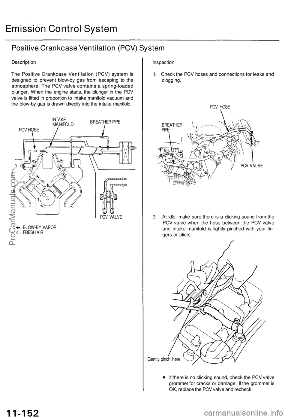
The Positive Crankcase Ventilation (PCV) system is
designed to prevent blow-by gas from escaping to the
atmosphere. The PCV valve contains a spring-loaded
plunger. When the engine starts, the plunger in the PCV
valve is lifted in proportion to intake manifold vacuum and
the blow-by gas is drawn directly into the intake manifold.
INTAKE
MANIFOLD
BREATHER PIPE
PCV HOSE
PCV VALVE
BLOW-BY VAPOR
FRESH AIR
Inspection
1. Check the PCV hoses and connections for leaks and
clogging.
PCV HOSE
BREATHER
PIPE
PCV VALVE
2.
At idle, make sure there is a clicking sound from the
PCV valve when the hose between the PCV valve
and intake manifold is lightly pinched with your fin-
gers or pliers.
Gently pinch here
If there is no clicking sound, check the PCV valve
grommet for cracks or damage. If the grommet is
OK, replace the PCV valve and recheck.ProCarManuals.com
Page 253 of 1771
Evaporative Emission (EVAP) Controls
Description
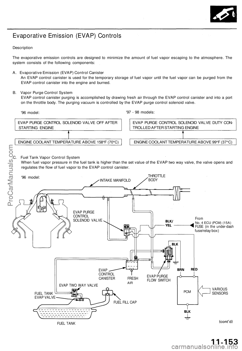
The evaporative emission controls are designed to minimize the amount of fuel vapor escaping to the atmosphere. The
system consists of the following components:
A. Evaporative Emission (EVAP) Control Canister
An EVAP control canister is used for the temporary storage of fuel vapor until the fuel vapor can be purged from the
EVAP control canister into the engine and burned.
B. Vapor Purge Control System
EVAP control canister purging is accomplished by drawing fresh air through the EVAP control canister and into a port
on the throttle body. The purging vacuum is controlled by the EVAP purge control solenoid valve.
'96 model:
'97 - 98 models:
C. Fuel Tank Vapor Control System
When fuel vapor pressure in the fuel tank is higher than the set value of the EVAP two way valve, the valve opens and
regulates the flow of fuel vapor to the EVAP control canister.
'96 model:
INTAKE MANIFOLD
THROTTLE
BODY
EVAP PURGE
CONTROL
SOLENOID VALVE
FUEL TANK
EVAP VALVE
EVAP TWO WAY VALVE
From
No. 4 ECU
(PCM) (15A)
FUSE (in the under-dash
fuse/relay box)
EVAP
CONTROL
CANISTER FRESH
AIR
EVAP PURGE
FLOW SWITCH
FUEL FILL CAP
PCM
VARIOUS
SENSORS
FUEL TANK
ENGINE COOLANT TEMPERATURE ABOVE 158°F (70°C)
ENGINE COOLANT TEMPERATURE ABOVE 99°F (37°C)
EVAP PURGE CONTROL SOLENOID VALVE DUTY CON-
TROLLED AFTER STARTING ENGINE
EVAP PURGE CONTROL SOLENOID VALVE OFF AFTER
STARTING ENGINEProCarManuals.com
Page 257 of 1771
Description
The automatic transmission is a combination of a 3-element torque converter and a dual-shaft electronically controlled
automatic transmission which provides 4 speeds forward and 1 reverse. The entire unit is positioned in line with the engine.
Torque Converter, Gears and Clutches
The torque converter consists of a pump, turbine, and stator, assembled in a single unit. They are connected to the engine
crankshaft so they turn together as a unit as the engine turns. Around the outside of the drive plate is a ring gear which
meshes with the starter pinion when the engine is being started.
The entire torque converter assembly serves as a flywheel while transmitting power to the transmission mainshaft.
The transmission has two parallel shafts: the mainshaft and the countershaft. The mainshaft is in line with the engine
crankshaft. The mainshaft includes the 1st, 4th and 2nd clutches and gears for 4th, 1st, 2nd and reverse (3rd gear is integral
with the mainshaft). The countershaft includes the 3rd, 1st-hold and reverse clutches, and gears for 3rd, 4th, 1st, 2nd,
reverse and parking. The secondary drive gear is integrated with the countershaft. The gears on the mainshaft are in con-
stant mesh with those on the countershaft. When certain combinations of gears in the transmission are engaged by clutch-
positions.
and
es, power is transmitted from the mainshaft to the countershaft to provide
Electronic Control
The electronic control system consists of a Powertrain Control Module (PCM), sensors, a linear solenoid and four solenoid
valves. Shifting and lock-up are electronically controlled for comfortable driving under all conditions.
The PCM is located below the dashboard, under the front lower panel on the passenger's side.
Hydraulic Control
The lower valve body assembly includes the main valve body, the secondary valve body, the throttle valve body, the lin-
ear solenoid, the shift control solenoid valves and the ATF passage body. They are bolted on the lower part of the trans-
mission housing. The regulator valve body, the ATF pump body, and the accumulator body are bolted to the torque con-
verter housing.
The main valve body on '96 model contains the manual valve, the 1-2 shift valve, the 2-3 shift valve, the 3-4 shift valve, the
4-3 kick-down valve and the Clutch Pressure Control (CPC) valve. The main valve body on '97 model contains the manual
valve, the 1-2 shift valve, the 2-3 shift valve, the 3-4 shift valve, the 4-3 kick-down valve and the main orifice control valve.
The secondary valve body on '96 model contains the 3-4 orifice control valve, the 4-3 shift timing valve, the modulator valve
and the accumulator pistons.The secondary valve body on '97 model contains the 3-4 orifice control valve, the 4-3 shift tim-
ing valve, the line pressure control valve, the modulator valve and the accumulator pistons. The throttle valve body
includes the throttle valve which is bolted onto the secondary valve body. The linear solenoid is joined to the throttle valve
body. The regulator valve body contains the regulator valve, the lock-up shift valve and the cooler relief valve. Fluid from
the regulator passes through the manual valve to the various control valves. The ATF pump body contains the lock-up tim-
ing valve, the lock-up control valve and the relief valve. The torque converter check valve is located in the torque converter
housing under the ATF pump body. The accumulator body contains the accumulator pistons. The reverse accumulator and
the 1st-hold accumulator pistons are assembled in the rear cover.
The 1st, 1st-hold, 2nd and reverse clutches receive fluid from their respective feed pipes, and the 3rd and 4th clutches
receive fluid from the internal hydraulic circuit.
Shift Control Mechanism
Input from various sensors located throughout the vehicle determines which shift control solenoid valve the PCM will acti-
vate. Activating a shift control solenoid valve changes modulator pressure, causing a shift valve to move. This pressurizes a
line to one of the clutches, engaging the clutch and its corresponding gear.
er through a fluid passage, causing the lock-up piston to be held against the torque converter cover. As this takes place, the
mainshaft rotates at the same speed as the engine crankshaft. Together with hydraulic control, the PCM optimizes the tim-
ing of the lock-up mechanism. The lock-up valves control the range of lock-up according to lock-up control solenoid valves
A and B, and throttle valve. When lock-up control solenoid valves A and B activate, modulator pressure changes. The lock-
up control solenoid valves A and B are mounted on the torque converter housing, and are controlled by the PCM.
(cont'd)
Lock-up Mechanism
In
position, in 2nd, 3rd, and 4th, and
position in 3rd, pressurized fluid is drained from the back of the torque convert-ProCarManuals.com
Page 265 of 1771
Position
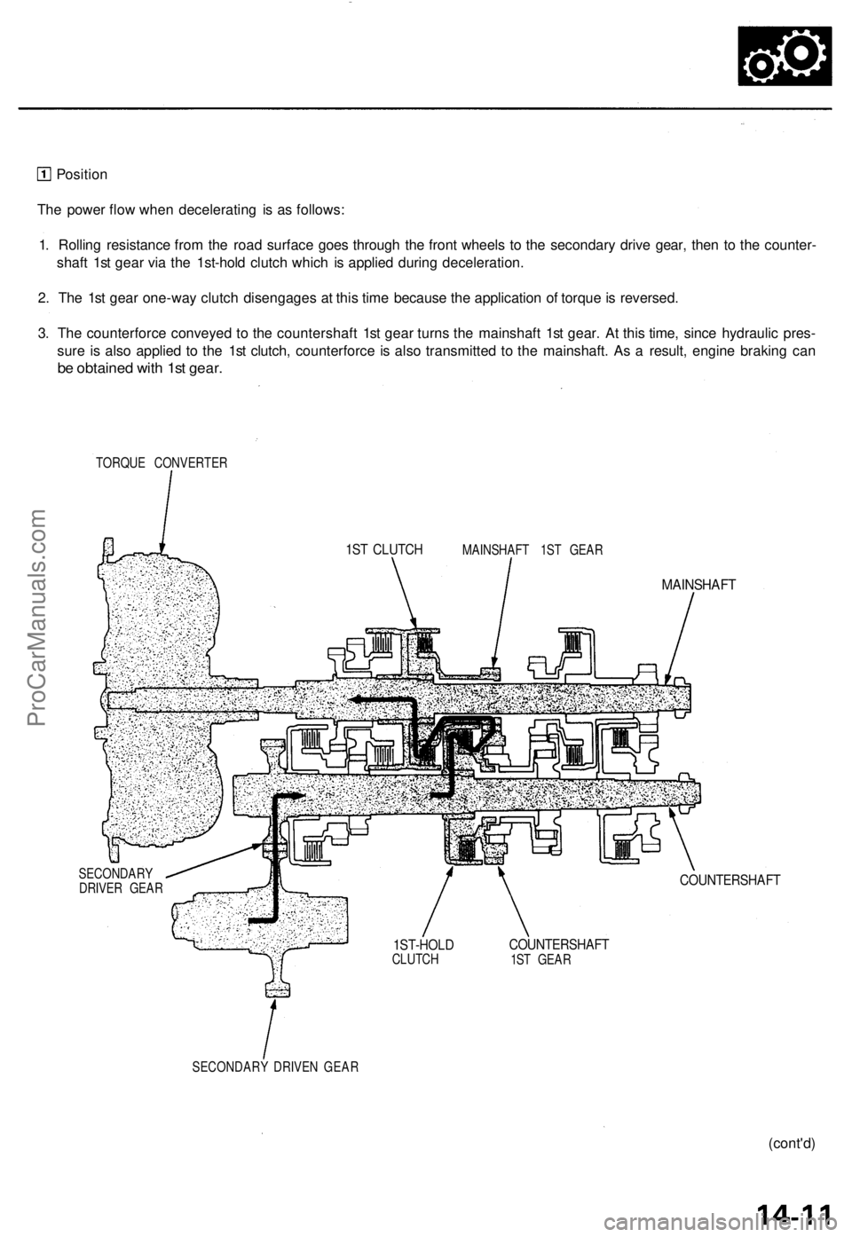
The power flow when decelerating is as follows:
1. Rolling resistance from the road surface goes through the front wheels to the secondary drive gear, then to the counter-
shaft 1st gear via the 1st-hold clutch which is applied during deceleration.
2. The 1st gear one-way clutch disengages at this time because the application of torque is reversed.
3. The counterforce conveyed to the countershaft 1st gear turns the mainshaft 1st gear. At this time, since hydraulic pres-
sure is also applied to the 1st clutch, counterforce is also transmitted to the mainshaft. As a result, engine braking can
be obtained with 1st gear.
TORQUE CONVERTER
MAINSHAFT 1ST GEAR
MAINSHAFT
SECONDARY
DRIVER GEAR
COUNTERSHAFT
COUNTERSHAFT
1ST GEAR
SECONDARY DRIVEN GEAR
(cont'd)
1ST CLUTCH
1ST-HOLD
CLUTCHProCarManuals.com