Page 205 of 1771
Idle Control System
System Description
The idle speed of the engine is controlled by the Idle Air Control (IAC) Valve.
The valve changes the amount of air bypassing into the intake manifold in response to electric current controlled by the
PCM. When the IAC Valve is activated, the valve opens to maintain the proper idle speed.
ENGINE
COOLANT
IAC VALVE
INTAKE
MANIFOLD
PCM
From
PGM-FI
MAIN
RELAY
FAST
IDLE
THERMO
VALVE
IDLE
ADJUSTING
SCREW
VARIOUS
SENSORS
ENGINE
COOLANTProCarManuals.com
Page 206 of 1771

Idle Contro l Syste m
System Descriptio n (cont'd )
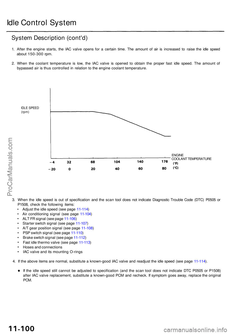
1. Afte r th e engine starts, th e IA C valv e open s fo r a certai n time . Th e amoun t o f ai r i s increase d t o rais e th e idl e spee d
about 150-30 0 rpm .
2. Whe n th e coolan t temperatur e i s low , th e IA C valv e i s opene d t o obtai n th e prope r fas t idl e speed . Th e amoun t o f
bypasse d ai r i s thu s controlle d i n relatio n t o th e engin e coolan t temperature .
IDLE SPEE D(rpm)
ENGIN ECOOLAN T TEMPERATUR E
3. Whe n th e idl e spee d i s ou t o f specificatio n an d th e sca n too l doe s no t indicat e Diagnosti c Troubl e Cod e (DTC ) P050 5 o r
P1508 , chec k th e followin g items :
Adjus t th e idl e spee d (se e pag e 11-114 )
Ai r conditionin g signa l (se e pag e 11-104 )
AL T F R signa l (se e pag e 11-106 )
Starte r switc h signa l (se e pag e 11-107 )
A/ T gea r positio n signa l (se e pag e 11-108 )
PS P switc h signa l (se e pag e 11-110 )
Brak e switc h signa l (se e pag e 11-112 )
Fas t idl e therm o valv e (se e pag e 11-113 )
Hose s an d connection s
IA C valv e an d it s mountin g O-ring s
4 . I f th e abov e item s ar e normal , substitut e a known-goo d IA C valv e an d readjus t th e idl e spee d (se e pag e 11-114 ).
I f th e idl e spee d stil l canno t b e adjuste d t o specificatio n (an d th e sca n too l doe s no t indicat e DT C P050 5 o r P1508 )
afte r IA C valv e replacement , substitut e a known-goo d PC M an d recheck . I f sympto m goe s away , replac e th e origina l
PCM.
ProCarManuals.com
Page 208 of 1771

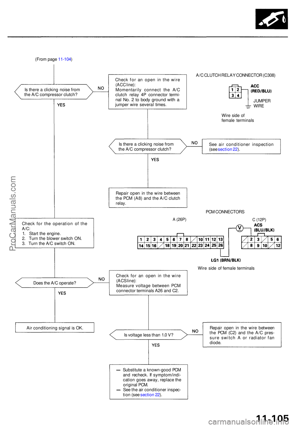
(From pag e 11-104 )
I s ther e a clickin g nois e fro m
th e A/ C compresso r clutch ?
Chec k fo r th e operatio n o f th e
A/C :1. Star t th e engine .
2 . Tur n th e blowe r switc h ON .
3 . Tur n th e A/ C switc h ON .
Doe s th e A/ C operate ?
Ai r conditionin g signa l i s OK . Chec
k fo r a n ope n i n th e wir e
(ACC line) :Momentaril y connec t th e A/ C
clutc h rela y 4 P connecto r termi -
nal No . 2 to bod y groun d wit h ajumpe r wir e severa l times . A/
C CLUTC H RELA Y CONNECTO R (C308 )
JUMPE RWIRE
Wire sid e o f
femal e terminal s
I s ther e a clickin g nois e fro m
th e A/ C compresso r clutch ? Se
e ai r conditione r inspectio n
(se e sectio n 22 ).
Repai r ope n in th e wir e betwee n
th e PC M (A8 ) an d th e A/ C clutc h
relay.
PCM CONNECTOR S
A (26P)
Chec k fo r a n ope n i n th e wir e
(AC S line) :
Measur e voltag e betwee n PC M
connecto r terminal s A2 6 an d C2 . Wir
e sid e o f femal e terminal s
I s voltag e les s tha n 1. 0 V ? Repai
r ope n i n th e wir e betwee n
th e PC M (C2 ) an d th e A/ C pres -
sur e switc h A or radiato r fa n
diode .
Substitut e a known-goo d PC M
an d recheck . I f symptom/indi -
catio n goe s away , replac e th e
origina l PCM .
Se e th e ai r conditione r inspec -
tio n (se e sectio n 22 ).
C (12P )
ProCarManuals.com
Page 209 of 1771

Idle Contro l Syste m
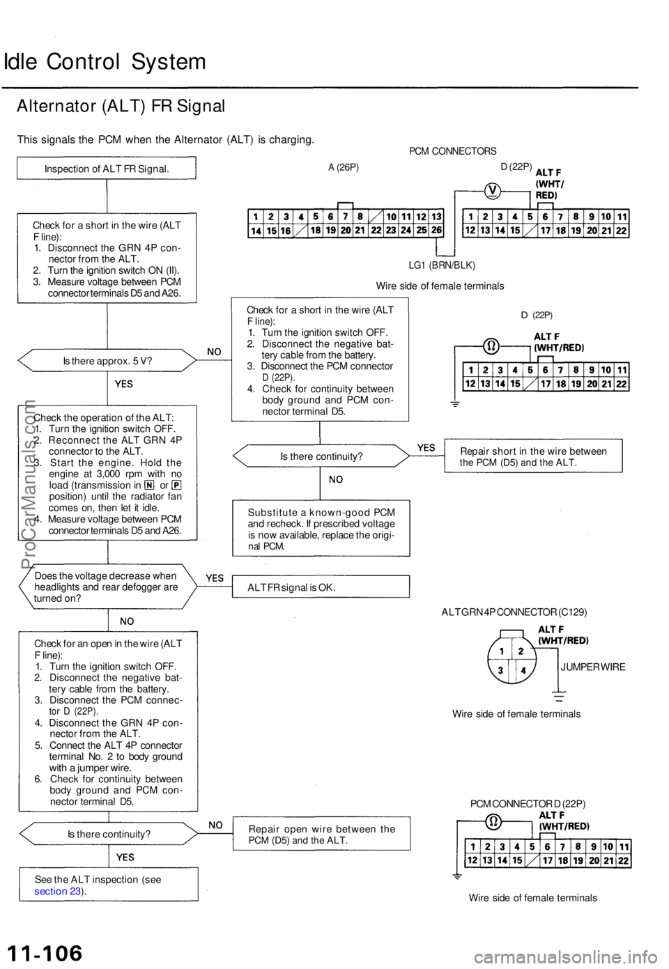
Alternato r (ALT ) F R Signa l
This signal s th e PC M whe n th e Alternato r (ALT ) i s charging .
Is ther e approx . 5 V ?
Chec k th e operatio n o f th e ALT :
1 . Tur n th e ignitio n switc h OFF .
2 . Reconnec t th e AL T GR N 4 P
connecto r t o th e ALT .
3 . Star t th e engine . Hol d th e
engin e a t 3,00 0 rp m wit h n o
loa d (transmissio n in o r
position ) unti l th e radiato r fa n
come s on , the n le t i t idle .
4 . Measur e voltag e betwee n PC M
connecto r terminal s D 5 an d A26 .
Doe s th e voltag e decreas e whe n
headlight s an d rea r defogge r ar e
turne d on ?
Chec k fo r a n ope n in th e wir e (AL T
F line) :
1 . Tur n th e ignitio n switc h OFF .
2 . Disconnec t th e negativ e bat -
ter y cabl e fro m th e battery .
3 . Disconnec t th e PC M connec -
tor D (22P) .4. Disconnec t th e GR N 4 P con -
necto r fro m th e ALT .
5 . Connec t th e AL T 4 P connecto r
termina l No . 2 to bod y groun d
with a jumpe r wire .6. Chec k fo r continuit y betwee n
bod y groun d an d PC M con -
necto r termina l D5 .
I s ther e continuity ?
Se e th e AL T inspectio n (se e
sectio n 23 ).
PC M CONNECTOR S
A (26P)D (22P )
LG1 (BRN/BLK )
Wire sid e o f femal e terminal s
Chec k fo r a shor t i n th e wir e (AL T
F line) :1. Tur n th e ignitio n switc h OFF .
2 . Disconnec t th e negativ e bat -
ter y cabl e fro m th e battery .
3 . Disconnec t th e PC M connecto r
D (22P) .4. Chec k fo r continuit y betwee n
bod y groun d an d PC M con -
necto r termina l D5 .
D (22P )
Is ther e continuity ? Repai
r shor t i n th e wir e betwee nthe PC M (D5 ) and th e ALT .
Substitut e a known-goo d PC M
an d recheck . I f prescribe d voltag e
i s no w available , replac e th e origi -
nal PCM .
ALT F R signa l i s OK .
ALT GR N 4P CONNECTO R (C129 )
JUMPE R WIR E
Wir e sid e o f femal e terminal s
Repai r ope n wir e betwee n th e
PC M (D5 ) and th e ALT .
Wire sid e o f femal e terminal s
PC
M CONNECTO R D (22P )
Chec
k fo r a shor t i n th e wir e (AL T
F line) :
1 . Disconnec t th e GR N 4 P con -
necto r fro m th e ALT .
2 . Tur n th e ignitio n switc h O N (II) .
3 . Measur e voltag e betwee n PC M
connecto r terminal s D 5 an d A26 .
Inspectio
n o f AL T F R Signal .
ProCarManuals.com
Page 210 of 1771
Starter Switch Signal
This signals the PCM when the engine is cranking.
PCM CONNECTORS
A
(26P)
C
(12P)
Wire side of female terminals
Is there battery voltage?
Is the fuse OK?
Repair short in the wire be-
tween the PCM (C6) and the
No. 9 STARTER SIGNAL (7.5
A) fuse or the PGM-FI main
relay.
Replace the No. 9 STARTER
SIGNAL (7.5 A) fuse.
Repair open in the wire between
the PCM
(C6)
and the No. 9
STARTER SIGNAL (7.5 A) fuse.
Starter switch signal is OK.
Inspect the No. 9 STARTER SIG-
NAL (7.5 A) fuse in the under-dash
fuse/relay box.
Check for an open or short in the
wire (STS line):
Measure voltage between PCM
connector terminals C6 and A26
with the ignition switch in the
start position (III).
Inspection of Starter Switch Sig-
nal.
NOTE: Transmission in or position.ProCarManuals.com
Page 212 of 1771
(From pag e 11-108 )
Chec k fo r a n ope n in th e wir e (AT P
P N line) :
1. Tur n th e ignitio n switc h OFF .2. Reconnec t th e 16 P connecto r
t o th e gaug e assembly .
3 . Star t th e engine .
4 . Measur e voltag e betwee n PC M
connecto r terminal s E2 4 an d
A26 wit h th e transmissio n inposition .
PCM CONNECTOR S
A (26P)E (26P)
Wire sid e o f femal e terminal s
I s ther e les s tha n 1. 0 V ? Repai
r ope n in th e wir e betwee n
the PC M (E24 ) an d the gaug e
assembly .
Check fo r a n ope n in th e wir e (AT PPN line) :Measur e voltag e betwee n PC M
connecto r terminal s E2 4 an d A2 6
with th e transmissio n i n posi -tion.
Is ther e les s tha n 1. 0 V ? Repai
r ope n in th e gaug e assem -bly.
A/T gea r positio n signa l i s OK .
ProCarManuals.com
Page 216 of 1771

Fast Idl e Therm o Valv e
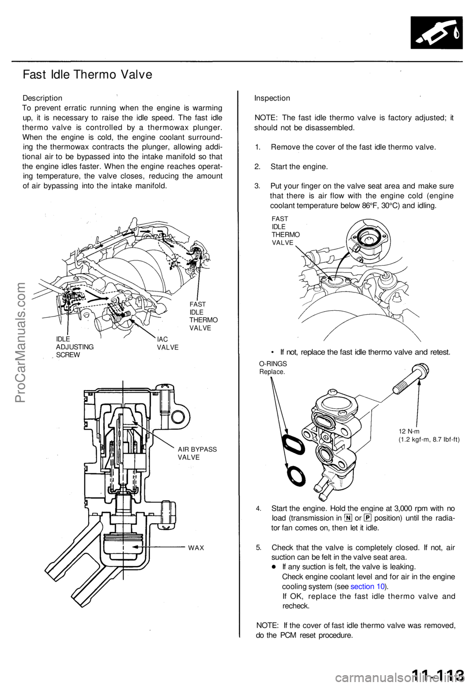
Descriptio n
T o preven t errati c runnin g whe n th e engin e i s warmin g
up , i t i s necessar y t o rais e th e idl e speed . Th e fas t idl e
therm o valv e i s controlle d b y a thermowa x plunger .
Whe n th e engin e i s cold , th e engin e coolan t surround -
in g th e thermowa x contract s th e plunger , allowin g addi -
tiona l ai r t o b e bypasse d int o th e intak e manifol d s o tha t
th e engin e idle s faster . Whe n th e engin e reache s operat -
in g temperature , th e valv e closes , reducin g th e amoun t
o f ai r bypassin g int o th e intak e manifold .
FASTIDLETHERM OVALVE
IDLEADJUSTIN GSCREW
IACVALV E
AIR BYPAS SVALVE
WAX
Inspectio n
NOTE: Th e fas t idl e therm o valv e i s factor y adjusted ; i t
shoul d no t b e disassembled .
1 . Remov e th e cove r o f th e fas t idl e therm o valve .
2 . Star t th e engine .
3.Pu t you r finge r o n th e valv e sea t are a an d mak e sur e
tha t ther e i s ai r flo w wit h th e engin e col d (engin e
coolan t temperatur e belo w 86°F , 30°C ) an d idling .
FASTIDLETHERM OVALVE
• I f not , replac e th e fas t idl e therm o valv e an d retest .
O-RING SReplace .
12 N- m(1.2 kgf-m , 8. 7 Ibf-ft )
4.
5.
Star t th e engine . Hol d th e engin e a t 3,00 0 rp m wit h n o
loa d (transmissio n in o r position ) unti l th e radia -
to r fa n come s on , the n le t i t idle .
Chec k tha t th e valv e i s completel y closed . I f not , ai r
suctio n ca n b e fel t i n th e valv e sea t area .
I f an y suctio n is felt , th e valv e is leaking .
Chec k engin e coolan t leve l an d fo r ai r i n th e engin e
coolin g syste m (se e sectio n 10 ).
I f OK , replac e th e fas t idl e therm o valv e an d
recheck .
NOTE: I f th e cove r o f fast idle therm o valv e wa s removed ,
d o th e PC M rese t procedure .
ProCarManuals.com
Page 217 of 1771

Idle Contro l Syste m
Idle Spee d Settin g
Inspection/Adjustmen t
NOTE:
Before settin g th e idl e speed , chec k th e followin g
items :
— Th e MI L ha s no t bee n reporte d on .
— Ignitio n timin g
— Spar k plug s
— Ai r cleane r (ACL )
— PC V syste m
(Canada ) Pul l th e parkin g brak e leve r up . Star t th e
engine , the n chec k tha t th e headlight s ar e off .
1 . Star t th e engine . Hol d th e engin e a t 3,00 0 rp m wit h
no loa d (transmissio n i n o r position ) unti l th e
radiato r fa n come s on , the n le t i t idle .
2 . Connec t a OBDI I sca n too l (se e pag e 11-32 ) o r
tachometer .
• Connec t a tachomete r t o th e ignitio n contro l
module (ICM ) secondary , or.. .
TACHOMETE R
ICM
Remov e th e rubbe r ca p fro m th e tachomete r
connecto r an d connec t a tachometer .
TACHOMETE R TACHOMETE R
CONNECTOR
RUBBERCAP
3. Disconnec t th e IA C valv e connector .
4.
5 .
IA C VALV E
Start th e engin e wit h th e accelerato r peda l slightl y
depressed . Stabiliz e th e rp m a t 1,000 , the n slowl y
releas e th e peda l unti l th e engin e idles .
Check idlin g in no-loa d conditions : headlights , blow -
er fan , rea r defogger , radiato r fan , an d ai r conditione r
ar e no t operating .
Idl e spee d shoul d be :
480 5 0 rp m
(in o r position )
Adjus t th e idl e speed , i f necessary , b y turnin g th e
idl e adjustin g screw .
NOTE : Afte r adjustin g th e idl e spee d i n thi s step ,
rechec k th e ignitio n timin g (se e sectio n 23 ).
I f i t i s ou t o f spec , g o bac k t o ste p 4 .
IDL E ADJUSTIN G SCRE W
ProCarManuals.com