Page 80 of 1771
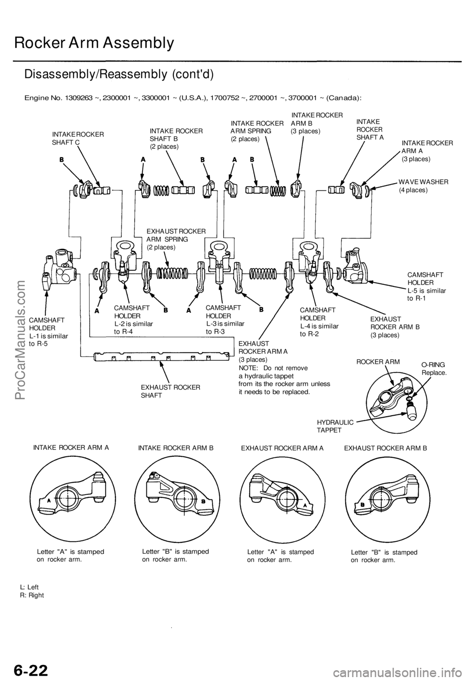
Rocker Arm Assembly
Disassembly/Reassembly (cont'd)
Engine No. 1309263 ~, 2300001 ~, 3300001 ~ (U.S.A.), 1700752 ~, 2700001 ~, 3700001 ~ (Canada):
INTAKE ROCKER
INTAKE ROCKER
SHAFT C
CAMSHAFT
HOLDER
L-1 is similar
to R-5
INTAKE ROCKER ARM B
INTAKE ROCKER ARM SPRING (3 places)
SHAFT B (2 places)
(2 places)
EXHAUST ROCKER
SHAFT
INTAKE
ROCKER
SHAFT A
INTAKE ROCKER
ARM A
(3 places)
WAVE WASHER
(4 places)
CAMSHAFT
HOLDER
L-5 is similar
to R-1
CAMSHAFT
HOLDER
L-4 is similar
to R-2
EXHAUST
ROCKER ARM A
(3 places)
NOTE: Do not remove
a hydraulic tappet
from its the rocker arm unless
it needs to be replaced.
HYDRAULIC
TAPPET
EXHAUST
ROCKER ARM B
(3 places)
ROCKER ARM
O-RING
Replace.
INTAKE ROCKER ARM A
INTAKE ROCKER ARM B
EXHAUST ROCKER ARM A
EXHAUST ROCKER ARM B
Letter "A" is stamped
on rocker arm.
Letter "B" is stamped
on rocker arm.
Letter "A" is stamped
on rocker arm.
Letter "B" is stamped
on rocker arm.
L: Left
R: Right
CAMSHAFT
HOLDER
L-3 is similar
to R-3
CAMSHAFT
HOLDER
L-2 is similar
to R-4
EXHAUST ROCKER
ARM SPRING
(2 places)ProCarManuals.com
Page 81 of 1771
Rocker Ar m Assembl y
Removal
NOTE:
Unscre w th e camshaf t holde r bolts , tw o turn s a t a
tim e i n a crisscros s pattern , t o preven t damagin g th e
valve s o r rocke r ar m assembly .
Whe n removin g th e rocke r ar m assembly , d o no t
remov e th e camshaf t holde r bolts . Th e bolt s wil l kee p
the camshaf t holders , th e spring s an d th e rocke r arm s
o n th e shafts .
CAMSHAF T HOLDE R BOLT S LOOSENIN G SEQUENCE :
Engin e No . 1300001~130926 2 (U.S.A.) , 1700001~170075 1 (Canada) :
6 m m BOLT S
8 m m BOLT S
Engine No . 1309263~ , 2300001~ , 3300001 ~ (U.S.A.) , 1700752~ , 270000 1 ~ ,
3700001 ~ (Canada) :
8 m m bolts :
NOTE : Refe r t o pag e 6-3 3 whe n installing .
ProCarManuals.com
Page 82 of 1771
Camshaft
Inspection
NOTE:
Do not rotate the camshaft during inspection.
Remove the rocker arms and rocker shafts.
1. Put the camshaft and the camshaft holders on the
cylinder head, then tighten the bolts to the specified
torque.
Specified torque:
8 mm bolts: 22 N-m (2.2 kgf-m, 16 Ibf-ft)
6 mm bolts: 12 N-m (1.2 kgf-m, 8.7 Ibf-ft)
Engine No. 1300001~1309262 (U.S.A.), 1700001~1700751 (Canada):
6 mm BOLTS
8 mm BOLTS
Engine No. 1309263~, 2300001 ~, 3300001~ (U.S.A.), 1700752~, 2700001-
3700001~ (Canada):
8 mm bolts:
2. Seat the camshaft by pushing it toward the rear end
of cylinder head.ProCarManuals.com
Page 94 of 1771
Hydraulic Tappets
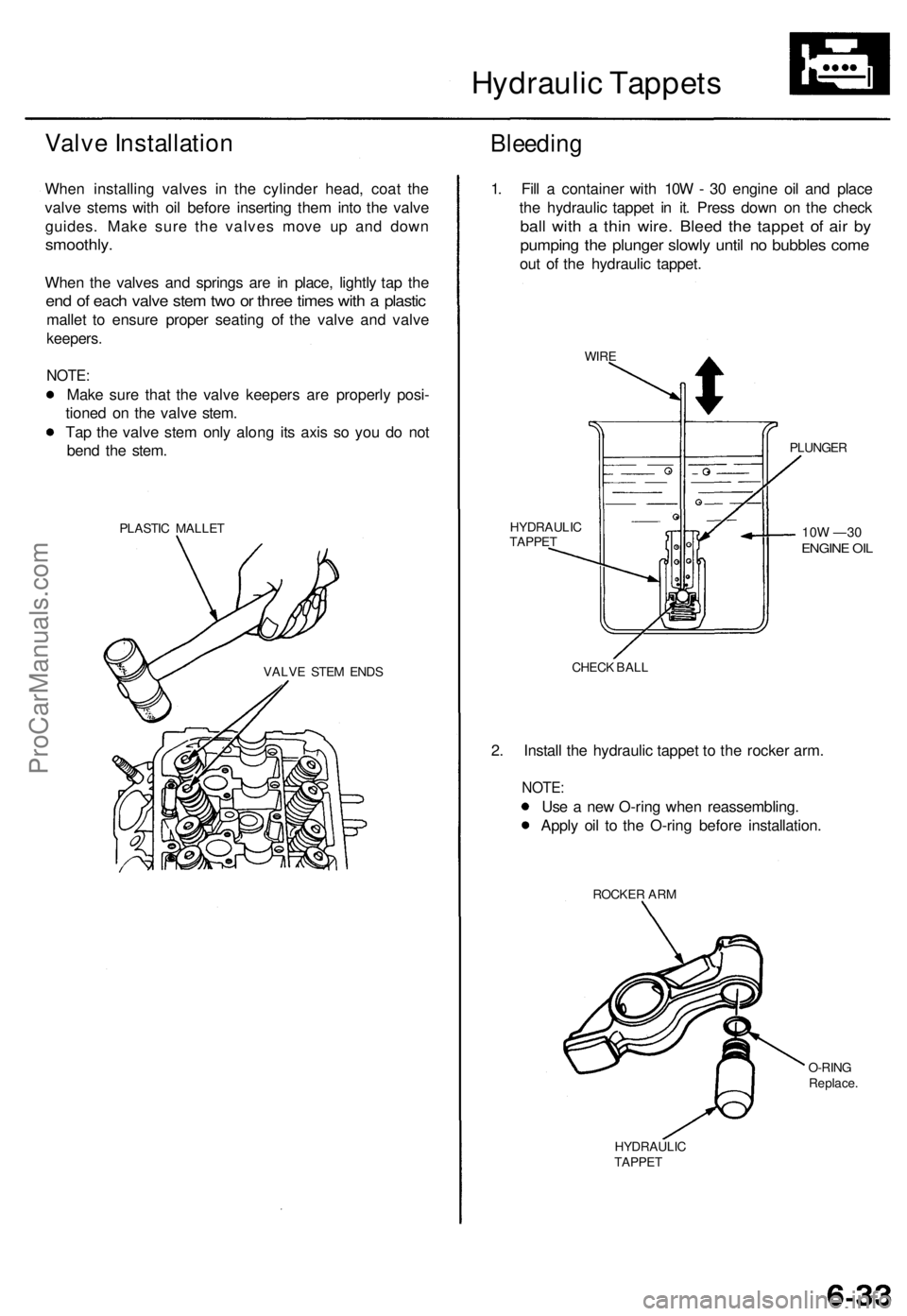
Valve Installation
When installing valves in the cylinder head, coat the
valve stems with oil before inserting them into the valve
guides. Make sure the valves move up and down
smoothly.
When the valves and springs are in place, lightly tap the
end of each valve stem two or three times with a plastic
mallet to ensure proper seating of the valve and valve
keepers.
NOTE:
Make sure that the valve keepers are properly posi-
tioned on the valve stem.
Tap the valve stem only along its axis so you do not
bend the stem.
PLASTIC MALLET
Bleeding
VALVE STEM ENDS
1. Fill a container with 10W - 30 engine oil and place
the hydraulic tappet in it. Press down on the check
ball with a thin wire. Bleed the tappet of air by
pumping the plunger slowly until no bubbles come
out of the hydraulic tappet.
WIRE
PLUNGER
10W —30
ENGINE OIL
HYDRAULIC
TAPPET
CHECK BALL
2. Install the hydraulic tappet to the rocker arm.
NOTE:
Use a new O-ring when reassembling.
Apply oil to the O-ring before installation.
ROCKER ARM
O-RING
Replace.
HYDRAULIC
TAPPETProCarManuals.com
Page 95 of 1771
Camshafts/Rocker Arms and Camshaft Seals
Installation
CAUTION:
Make sure that all rockers are in alignment with their
valves when torquing the rocker assembly bolts.
To prevent the rocker arm assembly from coming
apart, leave the camshaft holder bolts in the holes.
Handle the rocker arms carefully so that the oil does
not come out of the hydraulic tappets.
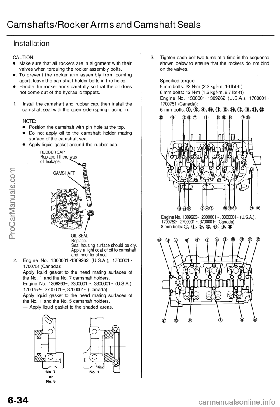
1.
2.
Install the camshaft and rubber cap, then install the
camshaft seal with the open side (spring) facing in.
NOTE:
Position the camshaft with pin hole at the top.
Do not apply oil to the camshaft holder mating
surface of the camshaft seal.
Apply liquid gasket around the rubber cap.
RUBBER CAP
Replace if there was
oil leakage.
CAMSHAFT
OIL SEAL
Replace.
Seal housing surface should be dry.
Apply a light coat of oil to camshaft
and inner lip of seal.
Engine No. 1300001~1309262 (U.S.A.), 1700001~
1700751 (Canada):
Apply liquid gasket to the head mating surfaces of
the No. 1 and the No. 7 camshaft holders.
Engine No. 1309263~, 2300001 ~, 3300001~ (U.S.A.),
1700752~, 2700001 ~, 3700001~ (Canada):
Apply liquid gasket to the head mating surfaces of
the No. 1 and the No. 5 camshaft holders.
— Apply liquid gasket to the shaded areas.
3. Tighten each bolt two turns at a time in the sequence
shown below to ensure that the rockers do not bind
on the valves.
Specified torque:
8 mm bolts: 22 N-m (2.2 kgf-m, 16 Ibf-ft)
6 mm bolts: 12 N-m (1.2 kgf-m, 8.7 Ibf-ft)
Engine No. 1300001~1309262 (U.S.A.), 1700001~
1700751 (Canada):
6 mm bolts:
Engine No. 1309263~, 2300001 ~, 3300001~ (U.S.A.),
1700752~, 2700001 ~. 3700001~ (Canada):
8 mm bolts:ProCarManuals.com
Page 97 of 1771
Cylinder Heads
Installation (cont'd)
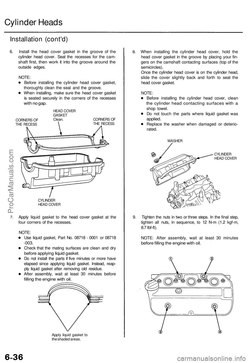
6. Install the head cover gasket in the groove of the
cylinder head cover. Seat the recesses for the cam-
shaft first, then work it into the groove around the
outside edges.
NOTE:
Before installing the cylinder head cover gasket,
thoroughly clean the seal and the groove.
When installing, make sure the head cover gasket
is seated securely in the corners of the recesses
with no gap.
CORNERS OF
THE RECESS
HEAD COVER
GASKET
Clean.
CORNERS OF
THE RECESS
7.
CYLINDER
HEAD COVER
Apply liquid gasket to the head cover gasket at the
four corners of the recesses.
NOTE:
Use liquid gasket, Part No. 08718 - 0001 or 08718
-003.
Check that the mating surfaces are clean and dry
before applying liquid gasket.
Do not install the parts if five minutes or more have
elapsed since applying liquid gasket. Instead, reap-
ply liquid gasket after removing old residue.
After assembly, wait at least 30 minutes before
filling the engine with oil.
Apply liquid gasket to
the shaded areas.
8.
When installing the cylinder head cover, hold the
head cover gasket in the groove by placing your fin-
gers on the camshaft contacting surfaces (top of the
semicircles).
Once the cylinder head cover is on the cylinder head,
slide the cover slightly back and forth to seat the
head cover gasket.
NOTE:
Before installing the cylinder head cover, clean
the cylinder head contacting surfaces with a
shop towel.
Do not touch the parts where liquid gasket was
applied.
Replace the washer when damaged or deterio-
rated.
WASHER
CYLINDER
HEAD COVER
9. Tighten the nuts in two or three steps. In the final step,
tighten all nuts, in sequence, to 12 N-m (1.2 kgf-m,
8.7 Ibf-ft).
NOTE: After assembly, wait at least 30 minutes
before filling the engine with oil.ProCarManuals.com
Page 103 of 1771
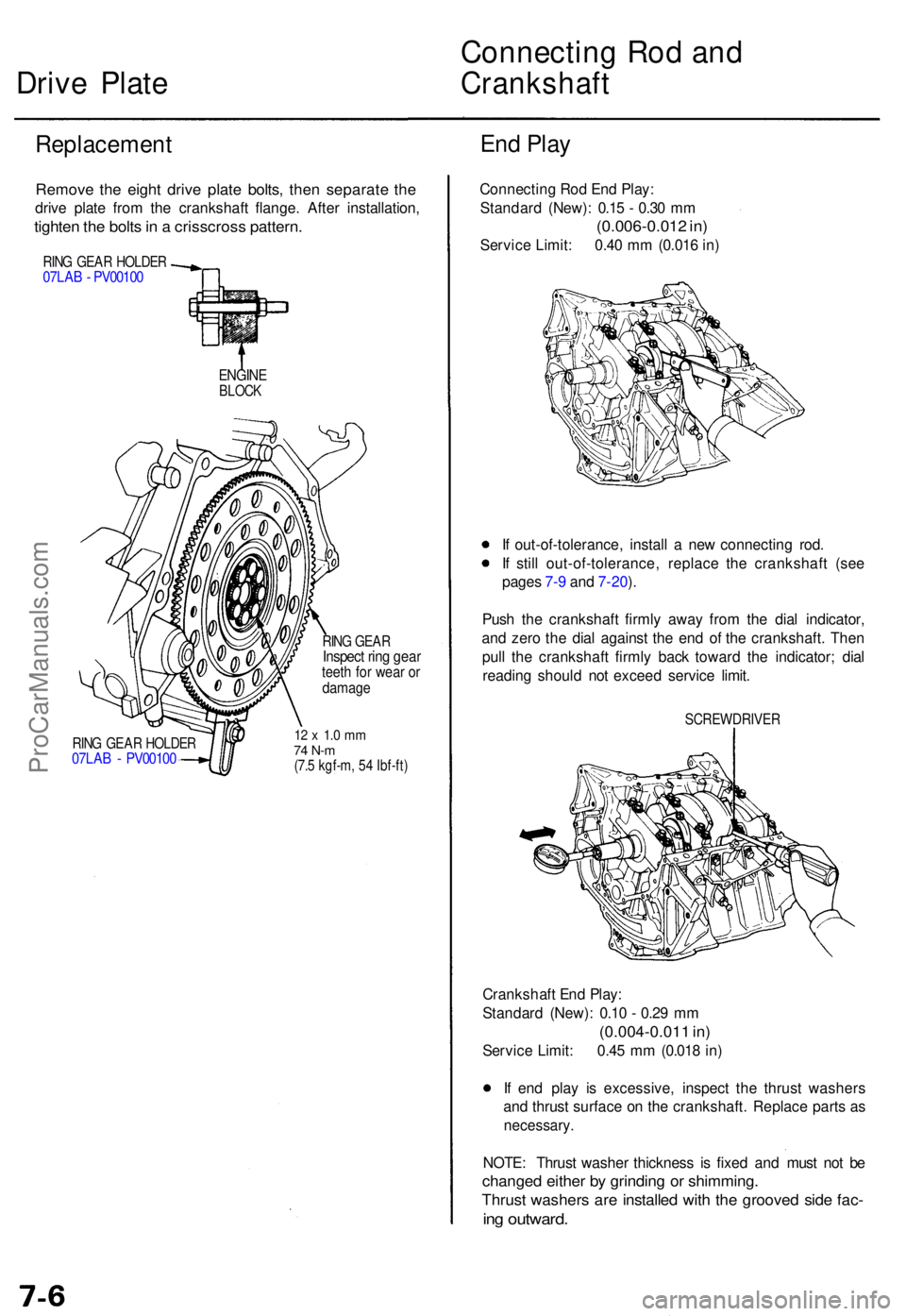
Drive Plat e Connectin
g Ro d an dCrankshaf t
Replacemen t En
d Pla y
Remov e th e eigh t driv e plat e bolts , the n separat e th e
driv e plat e fro m th e crankshaf t flange . Afte r installation ,
tighten th e bolt s in a crisscros s pattern .
RING GEA R HOLDE R07LAB - PV0010 0
ENGINEBLOCK
RING GEA R HOLDE R07LAB - PV0010 0
RING GEA RInspec t rin g gea rteeth fo r wea r o rdamag e
12 x 1. 0 m m74 N- m(7.5 kgf-m , 5 4 Ibf-ft )
Connectin g Ro d En d Play :
Standar d (New) : 0.1 5 - 0.3 0 m m
(0.006-0.01 2 in )
Servic e Limit : 0.4 0 m m (0.01 6 in )
I f out-of-tolerance , instal l a ne w connectin g rod .
I f stil l out-of-tolerance , replac e th e crankshaf t (se e
page s 7- 9 an d 7-20 ).
Pus h th e crankshaf t firml y awa y fro m th e dia l indicator ,
an d zer o th e dia l agains t th e en d o f th e crankshaft . The n
pul l th e crankshaf t firml y bac k towar d th e indicator ; dia l
readin g shoul d no t excee d servic e limit .
SCREWDRIVE R
Crankshaft En d Play :
Standar d (New) : 0.1 0 - 0.2 9 m m
(0.004-0.01 1 in )
Servic e Limit : 0.4 5 m m (0.01 8 in )
I f en d pla y i s excessive , inspec t th e thrus t washer s
an d thrus t surfac e o n th e crankshaft . Replac e part s a s
necessary .
NOTE: Thrus t washe r thicknes s i s fixe d an d mus t no t b e
change d eithe r b y grindin g o r shimming .
Thrust washer s ar e installe d wit h th e groove d sid e fac -
ing outward .
ProCarManuals.com
Page 107 of 1771
Pistons and Crankshaft
Removal (cont'd)
5. Remove the bearing from the cap. Keep all caps/bear-
ings in order.
6. Remove the upper bearing halves from the connect-
ing rods and set them aside with their respective caps.
7. Reinstall the cap on the rod after removing each
piston/connecting rod assembly.
8. To avoid mixup on reassembly, mark each piston/con-
necting rod assembly with its cylinder number.
NOTE: The existing number on the connecting rod
does not indicate its position in the engine, it indicates
the rod bore size.
9. Remove the bearing cap bolts and bearing cap side
bolts, then remove the bearing caps.
MAIN BEARING
CAP
RUBBER
CAP
To help with removal of the caps, install the cap
bolts in the outside bolt holes.
CAP BOLT
MAIN BEARING CAPS
10. Lift the crankshaft out of the cylinder block, being
careful not to damage the journals.
CRANKSHAFT
11. Reinstall the main caps and bearings on the cylin-
der block in proper order.ProCarManuals.com