Page 57 of 1771

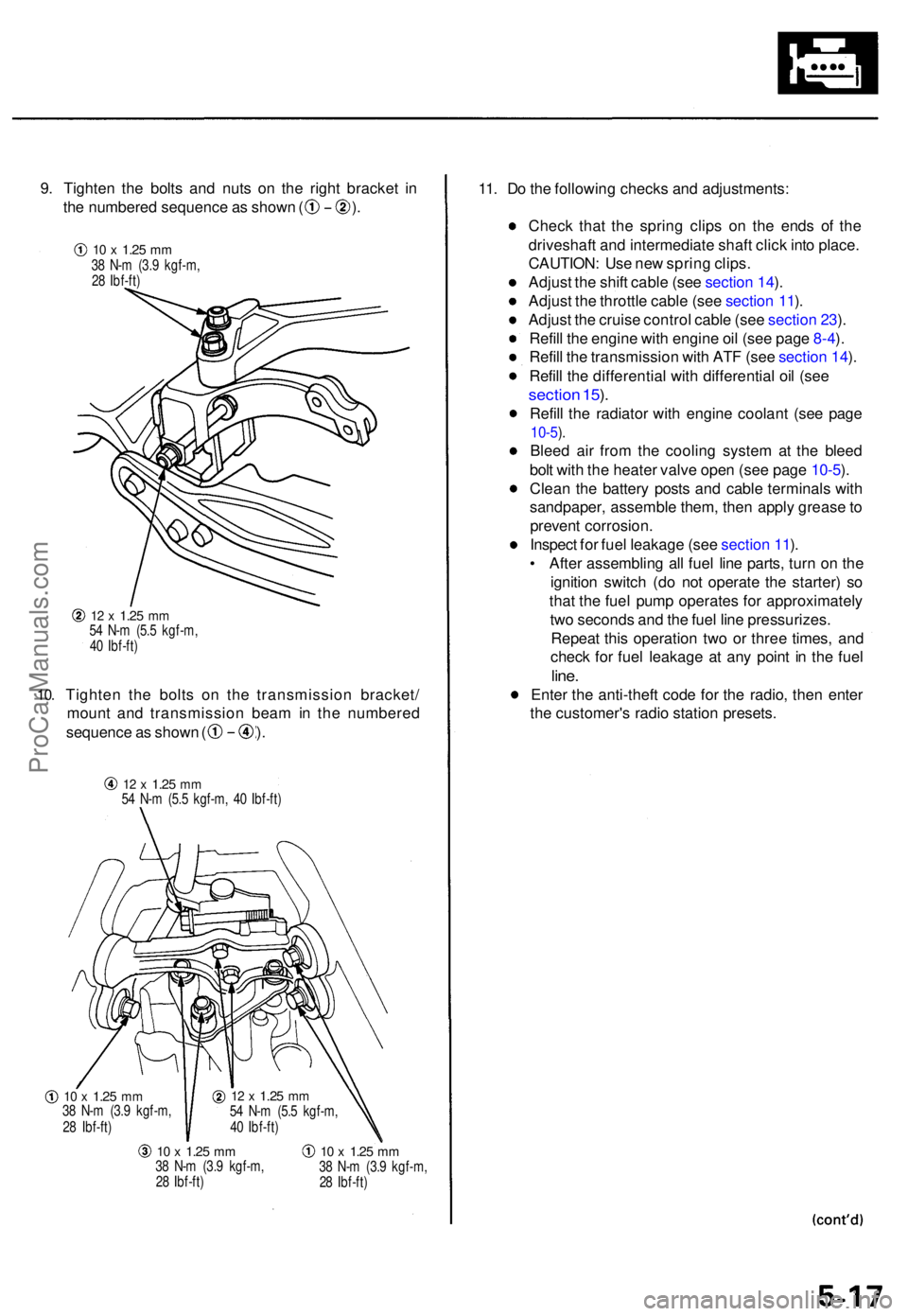
9. Tighte n th e bolt s an d nut s o n th e righ t bracke t i n
th e numbere d sequenc e a s show n ( ) .
10.
12 x 1.2 5 mm54 N- m (5. 5 kgf-m ,
4 0 Ibf-ft )
Tighte n th e bolt s o n th e transmissio n bracket /
moun t an d transmissio n bea m in th e numbere d
sequence a s show n ( ) .
12 x 1.2 5 mm54 N- m (5. 5 kgf-m , 4 0 Ibf-ft )
10 x 1.2 5 mm38 N- m (3. 9 kgf-m ,
2 8 Ibf-ft )
10 x 1.2 5 mm38 N- m (3. 9 kgf-m ,
2 8 Ibf-ft )10 x 1.2 5 mm38 N- m (3. 9 kgf-m ,
2 8 Ibf-ft )
11. D o th e followin g check s an d adjustments :
Chec k tha t th e sprin g clip s o n th e end s o f th e
driveshaf t an d intermediat e shaf t clic k int o place .
CAUTION : Us e ne w sprin g clips .
Adjus t th e shif t cabl e (se e sectio n 14 ).
Adjus t th e throttl e cabl e (se e sectio n 11 ).
Adjus t th e cruis e contro l cabl e (se e sectio n 23 ).
Refil l th e engine with engin e oi l (se e pag e 8-4 ).
Refil l th e transmissio n wit h AT F (se e sectio n 14 ).
Refil l th e differentia l wit h differentia l oi l (se e
sectio n 15 ).
Refil l th e radiato r wit h engine coolant (se e pag e
10-5).
Blee d ai r fro m th e coolin g syste m a t th e blee d
bol t wit h th e heate r valv e ope n (se e pag e 10-5 ).
Clea n th e batter y post s an d cabl e terminal s wit h
sandpaper , assembl e them , the n appl y greas e to
preven t corrosion .
Inspec t fo r fue l leakag e (se e sectio n 11 ).
• Afte r assemblin g al l fue l lin e parts , tur n o n th e
ignitio n switc h (d o no t operat e th e starter ) s o
tha t th e fue l pum p operates for approximatel y
tw o second s an d th e fue l lin e pressurizes .
Repea t thi s operatio n tw o o r thre e times , an d
chec k fo r fue l leakag e a t an y poin t i n th e fue l
line.
Ente r th e anti-thef t cod e fo r th e radio , the n ente r
th e customer' s radi o statio n presets .
12 x 1.2 5 mm54 N- m (5. 5 kgf-m ,
4 0 Ibf-ft )
10 x 1.2 5 mm38 N- m (3. 9 kgf-m ,
2 8 Ibf-ft )
ProCarManuals.com
Page 58 of 1771
Engine Removal/Installation
Installation (cont'd)
Mount and Bracket Bolts/Nuts Torque Value Specifications:
TRANSMISSION
MOUNT BRACKET
TRANSMISSION
MOUNT
12 x
1.25
mm
54 N-m (5.5 kgf-m,
40 Ibf-ft)
10 x
1.25
mm
38 N-m (3.9 kgf-m,
28 Ibf-ft)
10 x
1.25
mm
38 N-m (3.9 kgf-m,
28 Ibf-ft)
Replace.
RIGHT
MOUNT
DAMPER
8 x
1.25
mm
' 22 N-m (2.2 kgf-m,
16 Ibf-ft)
MID MOUNT
BRACKET
LEFT MOUNT
10 x
1.25
mm
38 N-m (3.9 kgf-m,
28 Ibf-ft)
Replace.
MID MOUNT
BRACKET
10 x
1.25
mm
38 N-m (3.9 kgf-m, 28 Ibf-ft)ProCarManuals.com
Page 64 of 1771
8. Disconnect the TCS throttle sensor connector and
TCS throttle actuator connector, then remove the
TCS control valve assembly.
Do not disconnect the breather pipe bypass hose.
TCS THROTTLE SENSOR
CONNECTOR
TCS THROTTLE
ACTUATOR CONNECTOR
TCS CONTROL VALVE
ASSEMBLY
9. Remove the oil pressure switch connector, engine
ground cable and engine wire harness cover.
6 x 1.0 mm
12 N-m (1.2 kgf-m, 8.7 Ibf-ft)
OIL PRESSURE
SWITCH CONNECTOR
ENGINE
GROUND
CABLE
ENGINE WIRE
HARNESS COVER
10. Remove the idler pulley bracket, dipstick and pipe.
6 x 1.0 mm
12 N-m (1.2 kgf-m,
8.7 Ibf-ft)
DIPSTICK/PIPE
8 x
1.25
mm
22 N-m (2.2 kgf-m, 16 Ibf-ft)
11. Remove the crankshaft pulley.
12. Remove the upper and lower covers.
NOTE: Do not use the upper and lower covers to
store removed items.
UPPER COVERS
Clean.
6 x 1.0 mm
12 N-m (1.2 kgf-m,
8.7 Ibf-ft)
LOWER COVER
Clean.
IDLER PULLEY
BRACKET
O-RING
Replace.ProCarManuals.com
Page 71 of 1771
NOTE: Clean the oil control orifice when installing.
CYLINDER HEAD BOLT
11 x 1.5 mm
76 N-m (7.8 kgf-m, 56 Ibf-ft)
Apply engine oil to the
bolt threads.
EXHAUST GAS
RECIRCULATION
(EGR) PASSAGE
8 x
1.25
mm
22 N-m (2.2 kgf-m,
16 Ibf-ft)
OIL CONTROL
ORIFICES
Remove with 6 x 1.0 mm
bolt and clean.
RIGHT CYLINDER
HEAD GASKET
Replace.
OIL CONTROL
ORIFICES
Remove with 6 x 1.0 mm
bolt and clean.
CYLINDER
HEAD
10 x
1.25
mm
44 N-m (4.5 kgf-m,
33 Ibf-ft)
LEFT CYLINDER
HEAD GASKET
Replace.
8 x
1.25
mm
22 N-m (2.2 kgf-m,
16 Ibf-ft)
DOWEL PIN
DOWEL PIN
O-RINGS
Replace.
GASKET
Replace.
CYLINDER
HEADProCarManuals.com
Page 73 of 1771

Cylinder Head s
Remova l
Engine remova l i s no t require d fo r thi s procedure .
Mak e sur e jack s an d safet y stand s ar e
place d properl y an d hois t bracket s ar e attache d th e t o
correc t position s o n th e engine .
CAUTION :
Us e fende r cover s t o avoi d damagin g painte d sur -
faces .
Unplu g th e wirin g connector s carefull y whil e holdin g
th e connecto r portio n to avoi d damage .
T o avoi d damagin g th e cylinde r head , wai t unti l th e
engin e coolan t temperatur e drop s belo w 100° F (38°C )
befor e loosenin g th e retainin g bolts .
NOTE :
Mark al l wirin g an d hose s t o avoi d misconnection .
Also , b e sur e tha t the y d o no t contac t othe r wirin g o r
hoses , o r interfer e wit h othe r parts .
Inspec t th e timin g bel t befor e removin g th e cylinde r
head .
Tur n th e crankshaf t pulle y s o tha t th e No . 1 pisto n i s
a t to p dea d cente r (se e pag e 6-10 ).
1 . Mak e sur e yo u hav e th e anti-thef t cod e fo r th e
radio , the n writ e dow n th e frequencie s fo r th e
radio' s prese t buttons .
2 . Disconnec t th e batter y negativ e termina l first , the n
the positiv e terminal .
3. Drai n th e engin e coolan t (se e pag e 10-5 ).
4 . Remov e th e engin e cove r (se e pag e 5-3 ).
5 . Remov e th e intak e ai r duc t an d ai r cleane r housin g
assembl y (se e pag e 5-3 ).
6 . Remov e th e throttl e cove r (se e pag e 5-4 ).
7 . Remov e th e throttl e cabl e an d cruis e contro l cabl e
b y loosenin g th e locknuts , the n sli p th e cabl e end s
ou t o f th e accelerato r linkag e (se e pag e 5-4 ).
NOTE :
Take car e no t t o ben d a cabl e whe n removin g it .
Alway s replac e an y kinke d cabl e wit h a ne w one .
Adjus t th e throttl e cabl e whe n installin g (se e
sectio n 11 ).
Adjus t th e cruis e contro l cabl e whe n installin g
(se e sectio n 23 ). 8
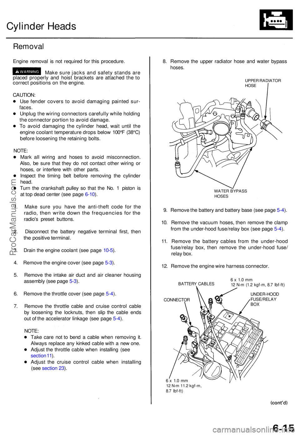
. Remov e th e uppe r radiato r hos e an d wate r bypas s
hoses.
UPPER RADIATO RHOSE
WATE R BYPAS SHOSES
9. Remov e th e batter y an d batter y bas e (se e pag e 5-4 ).
10 . Remov e th e vacuu m hoses , the n remov e th e clam p
fro m th e under-hoo d fuse/rela y bo x (se e pag e 5-4 ).
11 . Remov e th e batter y cable s fro m th e under-hoo d
fuse/rela y box , the n remov e th e under-hoo d fuse /
rela y box .
12 . Remov e th e engin e wir e harnes s connector .
BATTERY CABLE S
CONNECTO R
6 x 1. 0 m m12 N- m (1. 2 kgf-m , 8. 7 Ibf-ft )
UNDER-HOO DFUSE/RELAYBOX
6 x 1. 0 m m12 N- m 11. 2 kgf-m ,8.7 Ibf-ft )
ProCarManuals.com
Page 74 of 1771

Cylinder Head s
Remova l (cont'd )
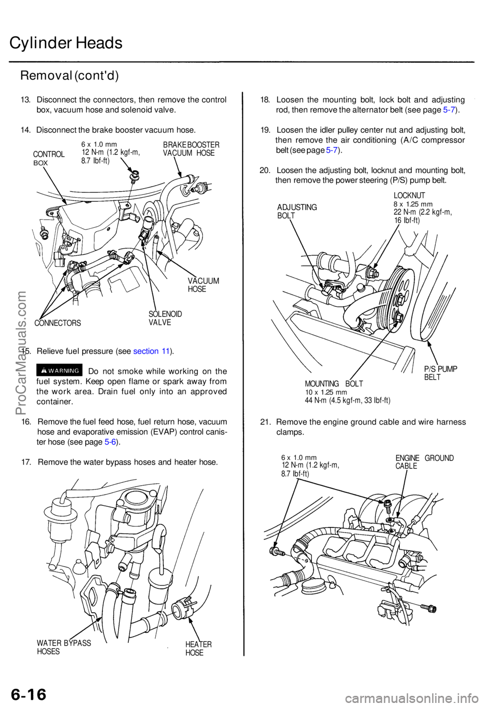
13. Disconnec t th e connectors , the n remov e th e contro l
box , vacuu m hos e an d solenoi d valve .
14 . Disconnec t th e brak e booste r vacuu m hose .
CONTRO LBOX
6 x 1. 0 m m12 N- m (1. 2 kgf-m ,
8. 7 Ibf-ft ) BRAK
E BOOSTE R
VACUU M HOS E
VACUU MHOSE
CONNECTOR S SOLENOI
D
VALVE
15. Reliev e fue l pressur e (se e sectio n 11 ).
D o no t smok e whil e workin g o n th e
fue l system . Kee p ope n flam e o r spar k awa y fro m
th e wor k area . Drai n fue l onl y int o a n approve d
container .
16 . Remov e th e fue l fee d hose , fue l retur n hose , vacuu m
hos e an d evaporativ e emissio n (EVAP ) contro l canis -
te r hos e (se e pag e 5-6 ).
17 . Remov e th e wate r bypas s hose s an d heate r hose .
WATE R BYPAS S
HOSE SHEATE RHOSE
18. Loose n th e mountin g bolt , loc k bol t an d adjustin g
rod , the n remov e th e alternato r bel t (se e pag e 5-7 ).
19 . Loose n th e idle r pulle y cente r nu t an d adjustin g bolt ,
the n remov e th e ai r conditionin g (A/ C compresso r
bel t (se e pag e 5-7 ).
20 . Loose n th e adjustin g bolt , locknu t an d mountin g bolt ,
the n remov e th e powe r steerin g (P/S ) pum p belt .
ADJUSTIN GBOLT LOCKNU
T
8 x 1.2 5 mm22 N- m (2. 2 kgf-m ,
1 6 Ibf-ft )
P/S PUM PBELTMOUNTIN G BOL T10 x 1.2 5 mm44 N- m (4. 5 kgf-m , 3 3 Ibf-ft )
21. Remov e th e engine ground cabl e an d wir e harnes s
clamps.
6 x 1. 0 m m12 N- m (1. 2 kgf-m ,
8. 7 Ibf-ft ) ENGIN
E GROUN DCABLE
ProCarManuals.com
Page 75 of 1771

22. Remove the positive crankcase ventilation (PCV)
hose.
23. Remove the bolt securing the automatic transmis-
sion fluid (ATF) dipstick tube bracket.
6 x 1.0 mm
12 N-m (1.2 kgf-m,
8.7 Ibf-ft)
ATF BRACKET
DIPSTICK TUBE
BRACKET
PCV HOSE
24.
Remove the engine wire harness connectors and
wire harness clamps from the cylinder heads and
intake manifold.
Six injector connectors
Six ignition coil connectors
Throttle position sensor connector
CKP/CYP sensor connector
Intake air temperature (IAT) sensor connector
Exhaust gas recirculation (EGR) valve lift sensor
connector
Idle air control (IAC) valve connector
Engine coolant temperature (ECT) sensor con-
nector
ECT gauge sending unit connector
Engine oil temperature sensor connector
Left primary heated oxygen sensor (left primary
HO2S) connector
Right primary heated oxygen sensor (right pri-
mary HO2S) connector
Evaporative emission (EVAP) purge control
solenoid valve connector ('97 - '98)
25. Remove the inlet pipe mounting bolts from the right
cylinder head cover.
26. Remove the vacuum hoses and breather hose.
6 x 1.0 mm
12 N-m (1.2 kgf-m, 8.7 Ibf-ft)
BREATHER
HOSE
VACUUM
HOSES
27. Remove the six ignition coils from the left and right
cylinder head covers.
6 x 1.0 mm
12 N-m (1.2 kgf-m, 8.7 Ibf-ft)
IGNITION
COILProCarManuals.com
Page 78 of 1771
Cylinder Heads
Removal (cont'd)
36. Remove the three bolts securing the alternator
bracket.
ALTERNATOR
BRACKET
8 x
1.25
mm
22 N-m (2.2 kgf-m,
16 Ibf-ft)
37. Remove the two bolts securing the P/S pump bracket.
P/S PUMP
BRACKET
10 x
1.25
mm
44 N-m (4.5 kgf-m,
33 Ibf-ft)
38. Remove the cylinder head bolts, then remove the
cylinder heads.
CAUTION: To prevent warpage, unscrew the bolts
in sequence 1/3 turn at a time; repeat the sequence
until all bolts are loose.
CYLINDER HEAD BOLTS LOOSENING SEQUENCE:
Engine No. 1300001-1309262 (U.S.A.), 1700001-1700751 (Canada):
Engine No. 1309263-, 2300001 ~, 3300001~ (U.S.A.), 1700752~, 2700001~
3700001~ (Canada):ProCarManuals.com