Page 9 of 1771
Emission Group Identification
(1998 model)
Example:
VACUUM HOSE ROUTING DIAGRAM
50ST (50 States):
THIS VEHICLE CONFORMS TO U.S. EPA AND STATE OF
CALIFORNIA REGULATIONS APPLICABLE TO 1998
MODEL YEAR NEW MOTOR VEHICLES.
49ST (49 States/Federal):
THIS VEHICLE CONFORMS TO U.S. EPA REGULATIONS
APPLICABLE TO 1998 MODEL YEAR NEW MOTOR VEHI-
CLES.
CAL (California):
THIS VEHICLE CONFORMS TO U.S. EPA AND STATE OF
CALIFORNIA REGULATIONS APPLICABLE TO 1998
MODEL YEAR NEW PASSENGER CARS PROVIDED
THAT THIS VEHICLE IS ONLY INTRODUCED INTO COM-
MERCE FOR SALE IN THE STATE OF CALIFORNIA.
Engine and Evaporative Families
Engine Family:
Evaporative Family:ProCarManuals.com
Page 12 of 1771
Towing
If the vehicle needs to be towed, call a professional tow-
ing service. Never tow the vehicle behind another vehi-
cle with just a rope or chain. It is very dangerous.
Emergency Towing
There are three popular methods of towing a vehicle:
Flat-bed Equipment — The operator loads the vehicle on
the back of a truck. This is the best way of transporting the
vehicle.
Wheel Lift Equipment — The tow truck uses two pivoting
arms that go under the tires (front or rear) and lifts them
off the ground. The other two wheels remain on the
ground.
Sling-type Equipment — The tow truck uses metal cables
with hooks on the ends. These hooks go around parts of
the frame or suspension and the cables lift that end of
the vehicle off the ground. The vehicle's suspension and
body can be seriously damaged if this method of towing
is attempted.
If the vehicle cannot be transported by flat-bed, it should
be towed with the front wheels off the ground. If due to
damage, the vehicle must be towed with the front
wheels on the ground, do the following:
Release the parking brake.
Start the engine.
Shift to position, then position.
Turn off the engine.
CAUTION:
Improper towing preparation will damage the trans-
mission. Follow the above procedure exactly. If you
cannot shift the transmission or start the engine, the
vehicle must be transported on a flat-bed.
It is best to tow the vehicle no farther than 50 miles
(80 km), and keep the speed below 35 mph (55 km/h).
Trying to lift or tow the vehicle by the bumpers will
cause serious damage. The bumpers are not designed
to support the vehicle's weight.
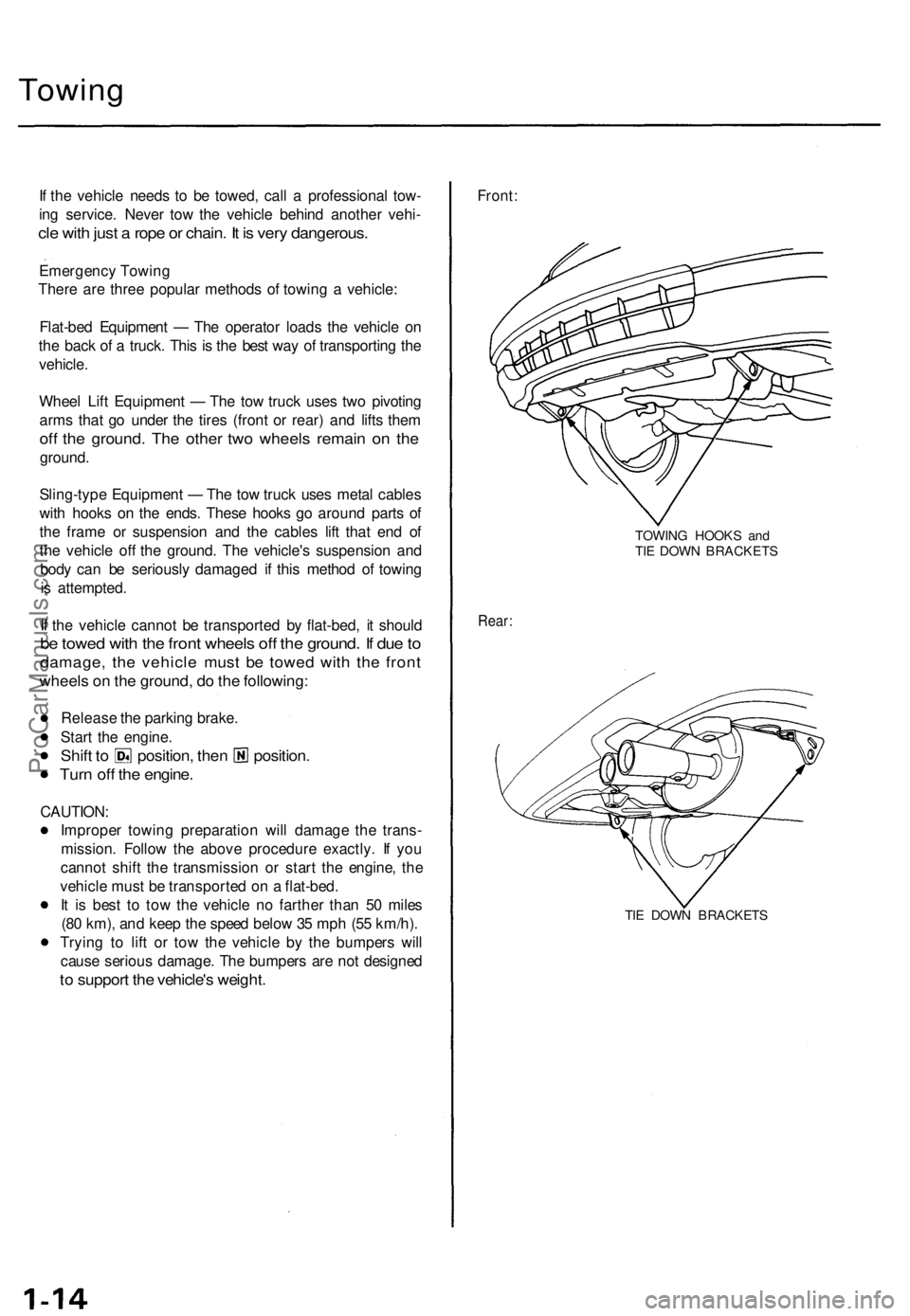
Front:
TOWING HOOKS and
TIE DOWN BRACKETS
Rear:
TIE DOWN BRACKETSProCarManuals.com
Page 14 of 1771
Engine Lubricatio n — Sectio n 8
Engin
e Bloc k — Sectio n 7
ProCarManuals.com
Page 28 of 1771

Lubrication Points
For the details of lubrication points and types of lubricants to be applied, refer to the illustrated index and various work
procedures (such as Assembly/Reassembly, Replacement, Overhaul, Installation, etc.) contained in each section.
No.
1
2
3
4
5
6
7
8
9
10
11
12
13
14
15
16
17
18
19
20
21
LUBRICATION POINTS
Engine
Transmission
Brake Line (Includes Anti-lock brake line)
Power steering gearbox
Steering boots
Throttle cable end
Steering ball joints
Shift lever (Automatic transmission)
Pedal linkage
Intermediate shaft
Brake master cylinder pushrod
Fuel
fill
lid
Trunk hinges
Door hinges upper and lower
Door opening detents
Hood hinges and hood latch
Brake pipe joint (Front and rear wheel house)
Caliper Piston seal, Dust seal,
Caliper pin, Piston
Power steering system
Differential
A/C compressor
LUBRICANT
API Service Grade: Use SH "Energy Conserving II" or SJ
"Energy Conserving" grade oil.
The oil container may also display the API Certification
mark shown below. Make sure it says "For Gasoline
Engines."
SAE Viscosity: See chart below.
Genuine Honda Premium Formula Automatic
Transmission Fluid (ATF)*1
Genuine Honda DOT3 Brake Fluid*2
Steering grease P/N 08733 - B070E
Multi-purpose grease
Honda White Lithium Grease
Rust preventives
Silicone grease
Genuine Honda Power Steering Fluid-V or S*3
Hypoid gear Oil API service GL4 or GL5
Viscosity:
at above -18°C (0°F): SAE 90
at less than -18°C (0°F): SAE 80 W-90
Compressor oil:
DENSO: ND-OIL8 (P/N 38897 - PR7 - A01 AH or 38899 -
PR7-A01)
(For Refrigerant: HFC-134a (R-134a))
API SERVICE LABEL
API CERTIFICATION MARK
Recommended Engine Oil
Engine oil viscosity for ambient temperature ranges
NOTE: The following information as marked *1, *2 and *3 on above chart details for 1997 model:
*1: Always use Genuine Honda Premium Formula Automatic Transmission Fluid (ATF). Using a non-Honda ATF can affect
shift quality.
*2: Always use Genuine Honda DOT3 Brake Fluid. Using a non-Honda brake fluid can cause corrosion and decrease the
life of the system.
*3: Always use Genuine Honda Power Steering Fluid-V or S. Using any other type of power steering fluid or automatic
transmission fluid can cause increase wear and poor steering in cold weather.ProCarManuals.com
Page 43 of 1771
Engine Removal/Installatio n
Removal
Make sur e jack s an d safet y stand s ar e place d properl y
an d hois t bracket s ar e attache d to th e correc t position s
o n th e engine .
Mak e sur e th e ca r wil l no t rol l of f stand s an d fal l
whil e yo u ar e workin g unde r it .
CAUTION :
Us e fende r cover s t o avoi d damagin g painte d sur -
faces .
Unplu g th e wirin g connector s carefull y whil e holdin g
th e connecto r portio n t o avoi d damage .
Mar k al l wirin g an d hose s t o avoi d misconnection .
Also , b e sur e tha t the y d o no t contac t othe r wirin g
o r hose s o r interfer e wit h othe r parts .
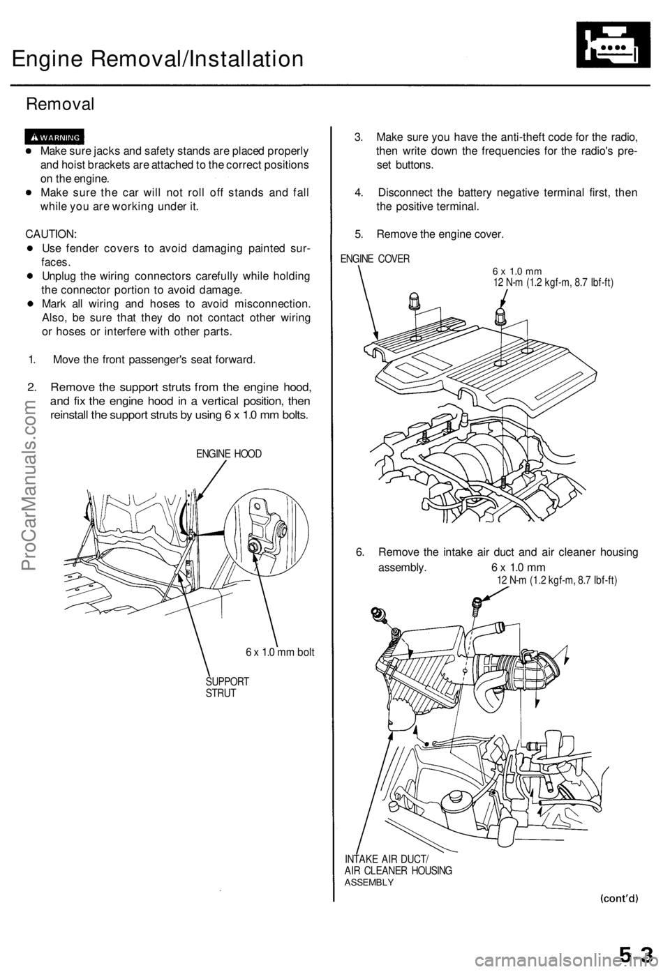
1 . Mov e th e fron t passenger' s sea t forward .
2. Remov e th e suppor t strut s fro m th e engin e hood ,
and fi x th e engin e hoo d in a vertica l position , the n
reinstal l th e suppor t strut s b y usin g 6 x 1. 0 m m bolts .
ENGIN E HOO D
6 x 1. 0 m m bol t
SUPPOR T
STRU T
3. Mak e sur e yo u hav e th e anti-thef t cod e fo r th e radio ,
the n writ e dow n th e frequencie s fo r th e radio' s pre -
se t buttons .
4 . Disconnec t th e batter y negativ e termina l first , the n
th e positiv e terminal .
5 . Remov e th e engin e cover .
ENGIN E COVE R6 x 1. 0 m m12 N- m (1. 2 kgf-m , 8. 7 Ibf-ft )
6. Remov e th e intak e ai r duc t an d ai r cleane r housin g
assembly . 6 x 1. 0 m m
12 N- m (1.2 kgf-m , 8. 7 Ibf-ft )
INTAK E AI R DUCT /
AI R CLEANE R HOUSIN G
ASSEMBL Y
ProCarManuals.com
Page 44 of 1771
Engine Removal/Installatio n
Removal (cont'd )
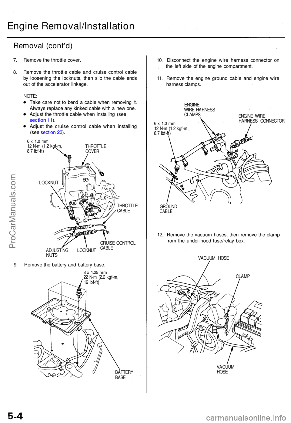
7. Remov e th e throttl e cover .
8.Remov e th e throttl e cabl e an d cruis e contro l cabl e
b y loosenin g th e locknuts , the n sli p th e cabl e end s
ou t o f th e accelerato r linkage .
NOTE:
Take car e no t t o ben d a cabl e whe n removin g it .
Alway s replac e an y kinke d cabl e wit h a ne w one .
Adjus t th e throttl e cabl e whe n installin g (se e
sectio n 11 ).
Adjus t th e cruis e contro l cabl e whe n installin g
(se e sectio n 23 ).
6 x 1. 0 m m12 N- m (1. 2 kgf-m ,
8. 7 Ibf-ft ) THROTTL
ECOVER
LOCKNU T
THROTTLE
CABLE
ADJUSTIN G LOCKNU TNUTS
CRUIS E CONTRO LCABLE
9. Remov e th e batter y an d batter y base .
8 x 1.2 5 mm22 N- m (2. 2 kgf-m ,
1 6 Ibf-ft )
BATTER YBASE
10. Disconnec t th e engin e wir e harnes s connecto r o n
th e lef t sid e o f th e engin e compartment .
11 . Remov e th e engin e groun d cabl e an d engin e wir e
harnes s clamps .
ENGINEWIRE HARNES S
CLAMP S
6 x 1. 0 m m12 N- m (1. 2 kgf-m ,
8. 7 Ibf-ft ) ENGIN
E WIR E
HARNES S CONNECTO R
GROUN D
CABLE
12. Remov e th e vacuu m hoses , the n remov e th e clam p
fro m th e under-hoo d fuse/rela y box .
VACUU M HOS E
CLAM P
VACUU M
HOS E
ProCarManuals.com
Page 45 of 1771
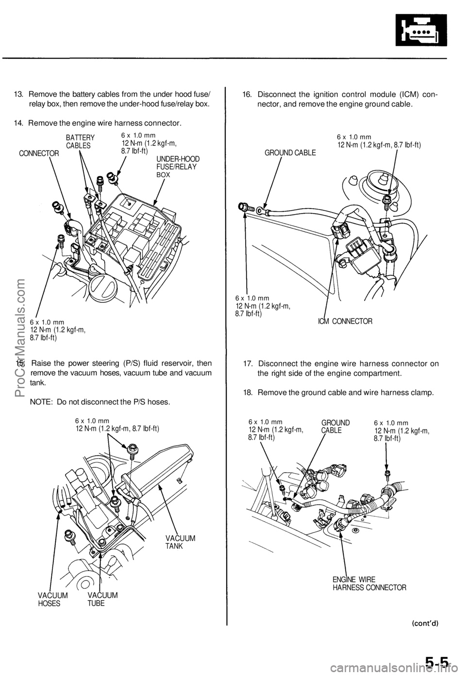
13. Remove the battery cables from the under hood fuse/
relay box, then remove the under-hood fuse/relay box.
14. Remove the engine wire harness connector.
BATTERY
CABLES
CONNECTOR
6 x 1.0 mm
12 N-m (1.2 kgf-m,
8.7 Ibf-ft)
UNDER-HOOD
FUSE/RELAY
BOX
6 x 1.0 mm
12 N-m (1.2 kgf-m,
8.7 Ibf-ft)
15. Raise the power steering (P/S) fluid reservoir, then
remove the vacuum hoses, vacuum tube and vacuum
tank.
NOTE: Do not disconnect the P/S hoses.
6 x 1.0 mm
12 N-m (1.2 kgf-m, 8.7 Ibf-ft)
VACUUM
TANK
VACUUM
HOSES
VACUUM
TUBE
16. Disconnect the ignition control module (ICM) con-
nector, and remove the engine ground cable.
GROUND CABLE
6 x 1.0 mm
12 N-m (1.2 kgf-m, 8.7 Ibf-ft)
6 x 1.0 mm
12 N-m (1.2 kgf-m,
8.7 Ibf-ft)
ICM CONNECTOR
17. Disconnect the engine wire harness connector on
the right side of the engine compartment.
18. Remove the ground cable and wire harness clamp.
6 x 1.0 mm
12 N-m (1.2 kgf-m,
8.7 Ibf-ft)
GROUND
CABLE
6 x 1.0 mm
12 N-m (1.2 kgf-m,
8.7 Ibf-ft)
ENGINE WIRE
HARNESS CONNECTORProCarManuals.com
Page 46 of 1771
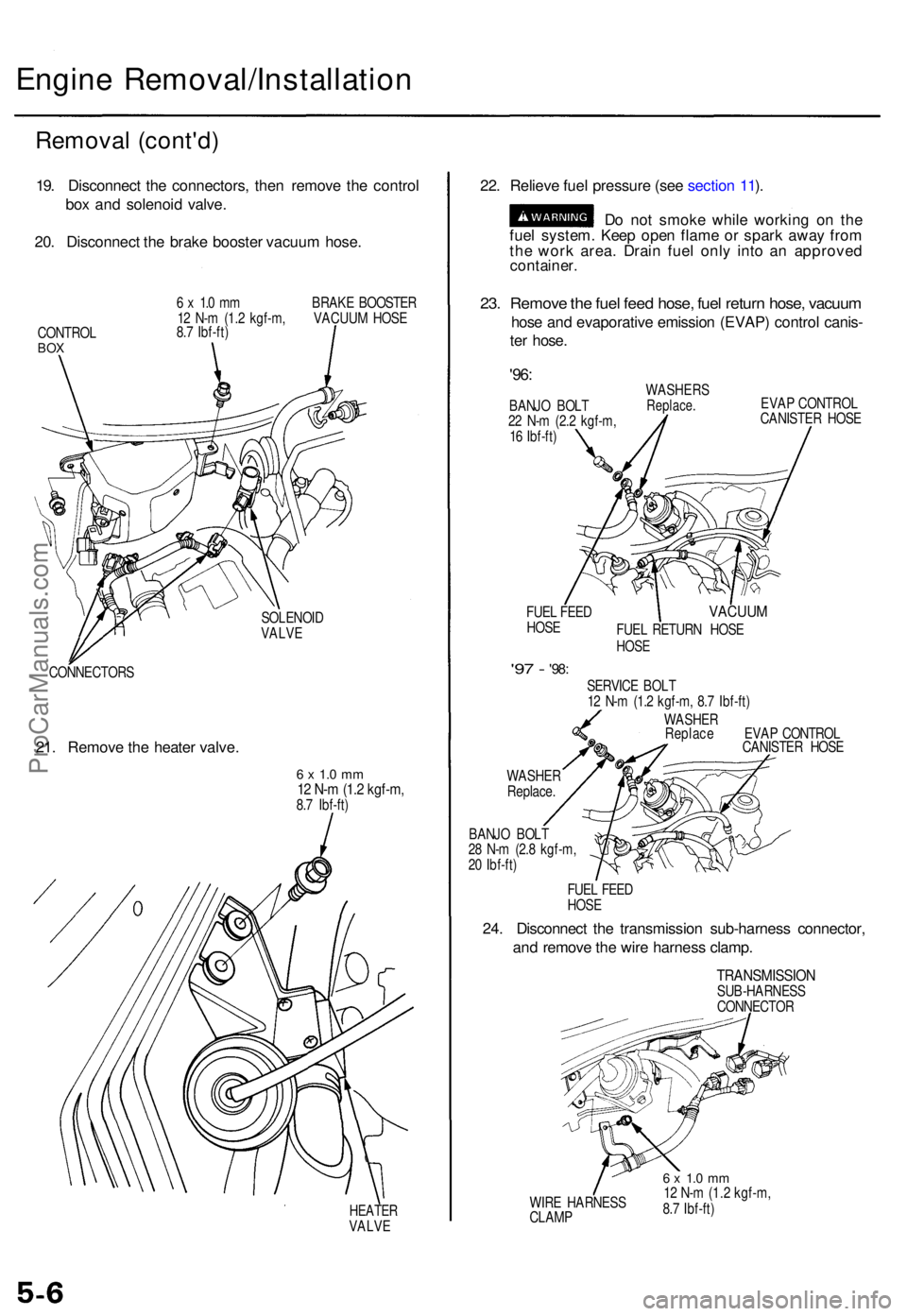
Engine Removal/Installatio n
Removal (cont'd )
19. Disconnec t th e connectors , the n remov e th e contro l
bo x an d solenoi d valve .
20 . Disconnec t th e brak e booste r vacuu m hose .
CONTRO LBOX
6 x 1. 0 m m BRAK E BOOSTE R
1 2 N- m (1. 2 kgf-m , VACUU M HOS E
8. 7 Ibf-ft )
SOLENOI D
VALVE
CONNECTOR S
21. Remov e th e heate r valve .
6 x 1. 0 m m12 N- m (1. 2 kgf-m ,8.7 Ibf-ft )
HEATE RVALVE
22. Reliev e fue l pressur e (se e sectio n 11 ).
D o no t smok e whil e workin g o n th e
fue l system . Kee p ope n flam e o r spar k awa y fro m
th e wor k area . Drai n fue l onl y int o a n approve d
container.
23. Remov e th e fue l fee d hose , fue l retur n hose , vacuu m
hose an d evaporativ e emissio n (EVAP ) contro l canis -
te r hose .
'96:
BANJ O BOL T
2 2 N- m (2. 2 kgf-m ,
1 6 Ibf-ft )WASHER SReplace.
FUEL FEE D
HOS E EVA
P CONTRO L
CANISTE R HOS EVACUU M
FUEL RETUR N HOS EHOSE
'97 - '98 :
WASHE R
Replace .SERVIC
E BOL T
1 2 N- m (1. 2 kgf-m , 8. 7 Ibf-ft )
WASHE R
Replac e EVA P CONTRO L
CANISTE R HOS E
BANJ O BOL T
2 8 N- m (2. 8 kgf-m ,
2 0 Ibf-ft )
FUEL FEE D
HOS E
24. Disconnec t th e transmissio n sub-harnes s connector ,
an d remov e th e wir e harnes s clamp .
TRANSMISSIO NSUB-HARNESS
CONNECTO R
WIR E HARNES S
CLAM P
6 x 1. 0 m m12 N- m (1. 2 kgf-m ,
8. 7 Ibf-ft )
ProCarManuals.com