Page 1580 of 1771
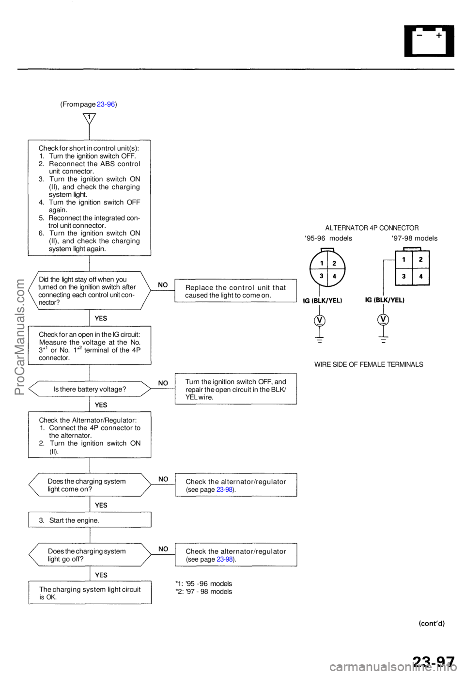
(From page 23-96 )
Chec k fo r shor t i n contro l unit(s) :
1 . Tur n th e ignitio n switc h OFF .
2 . Reconnec t th e AB S contro l
uni t connector .
3 . Tur n th e ignitio n switc h O N
(II) , an d chec k th e chargin g
system light .4. Tur n th e ignitio n switc h OF Fagain .5. Reconnec t th e integrate d con -trol uni t connector .6. Tur n th e ignitio n switc h O N
(II) , an d chec k th e chargin g
system ligh t again .
Did th e ligh t sta y of f whe n yo u
turne d o n th e ignitio n switc h afte r
connectin g eac h contro l uni t con -
nector ?
Check fo r a n ope n in th e IG circuit :
Measur e th e voltag e a t th e No .
3*
1 o r No . 1*2 termina l o f th e 4 Pconnector .
ALTERNATO R 4 P CONNECTO R
'95-96 model s '97-9 8 model s
Replac e th e contro l uni t tha t
cause d th e ligh t t o com e on .
WIR E SID E O F FEMAL E TERMINAL S
Is ther e batter y voltage ? Tur
n th e ignitio n switc h OFF , an d
repai r th e ope n circui t i n th e BLK /YEL wire .
Chec k th e Alternator/Regulator :1. Connec t th e 4 P connecto r t o
th e alternator .
2 . Tur n th e ignitio n switc h O N
(II).
Doe s th e chargin g syste m
ligh t com e on ? Chec
k th e alternator/regulato r(see pag e 23-98 ).
3 . Star t th e engine .
Doe s th e chargin g syste m
ligh t g o off ? Chec
k th e alternator/regulato r
(see pag e 23-98 ).
Th e chargin g syste m ligh t circui tis OK .
*1: '9 5 -9 6 model s*2: '9 7 - 9 8 model s
ProCarManuals.com
Page 1581 of 1771
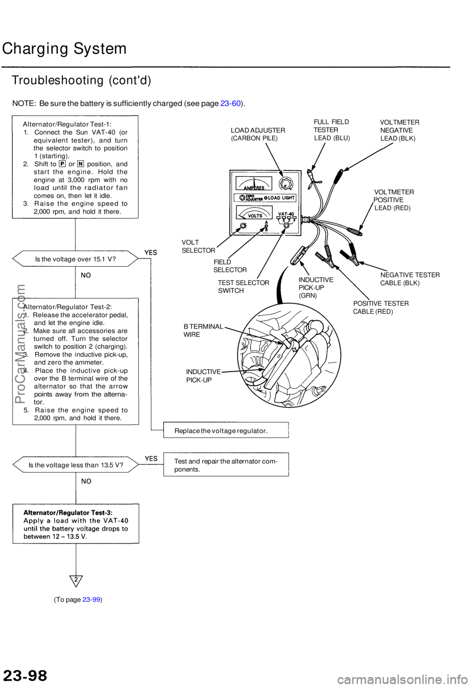
Charging Syste m
Troubleshootin g (cont'd )
NOTE: B e sur e th e batter y is sufficientl y charge d (se e pag e 23-60 ).
Alternator/Regulato r Test-1 :
1 . Connec t th e Su n VAT-4 0 (o r
equivalen t tester) , an d tur n
th e selecto r switc h t o positio n
1 (starting) .
2. Shif t t o o r position , an d
star t th e engine . Hol d th e
engin e a t 3,00 0 rp m wit h n o
loa d unti l th e radiato r fa ncome s on , the n le t i t idle .
3 . Rais e th e engin e spee d t o
2,00 0 rpm , an d hol d i t there .
I s th e voltag e ove r 15. 1 V ?
I s th e voltag e les s tha n 13. 5 V ? LOA
D ADJUSTE R
(CARBON PILE )
FULL FIEL DTESTE RLEAD (BLU )
VOLTMETE RNEGATIVELEAD (BLK )
VOLTSELECTO R
FIELDSELECTO R
B TERMINA LWIRE
INDUCTIV EPICK-UP
VOLTMETE RPOSITIVELEAD (RED )
NEGATIV E TESTE RCABLE (BLK )
POSITIV E TESTE RCABLE (RED )
Replac e th e voltag e regulator .
Tes t an d repai r th e alternato r com -
ponents .
(T o page 23-99) INDUCTIV
E
PICK-UP(GRN)
TEST SELECTO RSWITCH
Alternator/Regulato r Test-2 :
1 . Releas e th e accelerato r pedal ,
an d le t th e engin e idle .
2 . Mak e sur e al l accessorie s ar e
turne d off . Tur n th e selecto r
switc h t o positio n 2 (charging) .
3 . Remov e th e inductiv e pick-up ,
an d zer o th e ammeter .
4 . Plac e th e inductiv e pick-u p
ove r th e B termina l wire of th e
alternato r s o tha t th e arro w
points awa y fro m th e alterna -tor.5. Rais e th e engin e spee d t o
2,00 0 rpm , an d hol d i t there .
ProCarManuals.com
Page 1592 of 1771
Gauge Assembl y
Componen t Locatio n Inde x
FUEL GAUG E SENDIN G UNI T
Test , pag e 23-12 1
VEHICLE SPEE D SENSO R (VSS )
Troubleshooting , pag e 23-11 7
Replacement , pag e 23-12 0
PARKIN G BRAK E SWITC H
Test , pag e 23-12 5
ENGINE OI L PRESSUR E SWITC H
Test , pag e 23-12 0 ENGIN
E COOLAN T TEMPERATUR E (ECT )
GAUG E SENDIN G UNI TTest , pag e 23-12 4
BRAK
E FLUI D LEVE L SWITC H
Test , pag e 23-12 5
GAUG
E ASSEMBL Y
Gauge/Termina l Location s Index , pag e 23-11 1
Removal , pag e 23-11 4
Bulb Locations , pag e 23-11 5Disassembly , pag e 23-11 6
ProCarManuals.com
Page 1595 of 1771
Bulb Locations
GAUGE LIGHTS
(1.4
W x 2)
HIGH BEAM INDICATOR LIGHT (1.4 W)
SEAT BELT REMINDER LIGHT (1.4 W)
RIGHT TURN SIGNAL INDICATOR LIGHT (1.4 W)
MALFUNCTION INDICATOR LAMP
(MIL) (1.4
W)
LOW FUEL
INDICATOR LIGHT (3 W)
BRAKE SYSTEM LIGHT (1.4 W)
LEFT TURN SIGNAL INDICATOR LIGHT (1.4 W)
SRS INDICATOR LIGHT (1.4 W)
(On the SRS printed circuit board)
CHARGING SYSTEM LIGHT (1.4 W)
LOW ENGINE OIL PRESSURE
INDICATOR LIGHT (1.4 W)
ABS INDICATOR LIGHT (1.4 W)
DRL INDICATOR
LIGHT (1.4 W) (Canada)
CRUISE LIGHT (2 W)
A/T GEAR POSITION INDICATOR LIGHTS (1.12 W x 7)
GAUGE LIGHTS
(3.4
W x 2)
SAFETY
INDICATOR
LIGHTS
(1.12
W x 6)
GAUGE LIGHTS
(3.4
W x 3)ProCarManuals.com
Page 1596 of 1771
Gauge Assembl y
Disassembl y
TACHOMETE R MOUNTIN G SCRE W (x 3 )
ENGIN E COOLAN T
TEMPERATUR E (ECT )
GAUG E
MOUNTIN G SCREW S ( x 3 ) SR
S INDICATO R PRINTE D
CIRCUI T BOAR D
SPEEDOMETE R MOUNTIN G SCREW S (x 4 )
FUE L GAUG E
MOUNTIN G SCREW S ( x 3 )
BUL B HOUSIN G (ILLUMINATION )
PRINTED CIRCUI T BOAR D
HOUSIN G
SAFETY INDICATO R
PRINTE D CIRCUI T BOAR D
A/ T GEA R POSITIO N INDICATO R
DIMMING PRINTE D CIRCUI T BOAR D
ENGINE COOLAN T
TEMPERATUR E (ECT ) GAUG E
Test , pag e 23-12 4
SPEEDOMETE RSpecification, pag e 23-11 1 FUE L GAUG E
Test , pag e 23-12 1
TACHOMETE R
Specification, page 23-111
METE R VISO R METE
R PANE L
ProCarManuals.com
Page 1600 of 1771
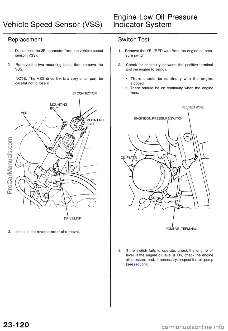
Engine Lo w Oi l Pressur e
Vehicle Spee d Senso r (VSS ) Indicato r Syste m
Replacemen t
1. Disconnec t th e 3 P connecto r fro m th e vehicl e spee d
senso r (VSS) .
2. Remov e th e tw o mountin g bolts , the n remov e th e
VSS .
NOTE : Th e VS S driv e lin k i s a ver y smal l part ; b e
carefu l no t t o los e it .
3P CONNECTO R
VSS
MOUNTIN GBOLT
DRIV E LIN K
3. Instal l i n th e revers e orde r o f removal .
Switch Tes t
1. Remov e th e YEL/RE D wir e fro m th e engin e oi l pres -
sur e switch .
2 . Chec k fo r continuit y betwee n th e positiv e termina l
an d th e engin e (ground) .
• Ther e shoul d b e continuit y wit h th e engin e
stopped .
• Ther e shoul d b e n o continuit y whe n th e engin e
runs.
YEL/RE D WIR E
ENGIN E OI L PRESSUR E SWITC H
OIL FILTE R
POSITIV E TERMINA L
3. I f th e switc h fail s t o operate , chec k th e engin e oi l
level . I f th e engin e oi l leve l i s OK , chec k th e engin e
oi l pressur e and , i f necessary , inspec t th e oi l pum p
(se e sectio n 8 ).
MOUNTIN GBOLT
ProCarManuals.com
Page 1604 of 1771
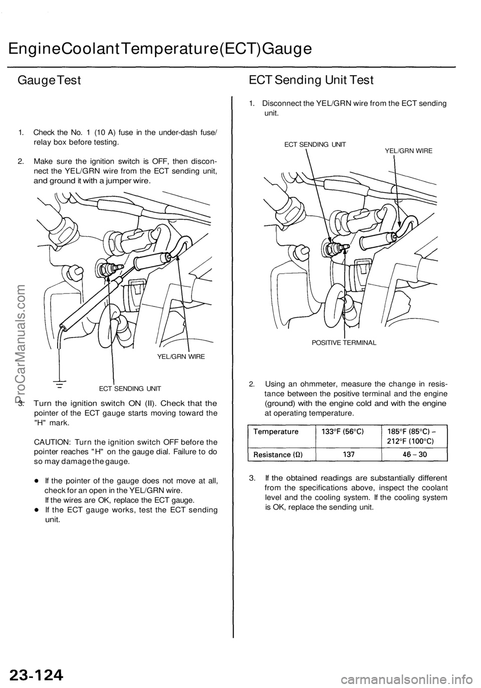
Engine Coolan t Temperatur e (ECT ) Gaug e
Gauge Tes t
1. Chec k th e No . 1 (1 0 A ) fus e in th e under-das h fuse /
rela y bo x befor e testing .
2 . Mak e sur e th e ignitio n switc h i s OFF , the n discon -
nec t th e YEL/GR N wir e fro m th e EC T sendin g unit ,
and groun d it wit h a jumpe r wire .
3.
YEL/GR N WIR E
EC T SENDIN G UNI T
Turn th e ignitio n switc h O N (II) . Chec k tha t th e
pointe r o f th e EC T gaug e start s movin g towar d th e
"H " mark .
CAUTION : Tur n th e ignitio n switc h OF F befor e th e
pointe r reache s "H " o n th e gaug e dial . Failur e t o d o
s o ma y damag e th e gauge .
I f th e pointe r o f th e gaug e doe s no t mov e a t all ,
chec k fo r a n ope n in th e YEL/GR N wire .
I f th e wire s ar e OK , replac e th e EC T gauge .
I f th e EC T gaug e works , tes t th e EC T sendin g
unit.
ECT Sendin g Uni t Tes t
1. Disconnec t th e YEL/GR N wir e fro m th e EC T sendin g
unit .
ECT SENDIN G UNI TYEL/GR N WIR E
2.
POSITIV E TERMINA L
Using a n ohmmeter , measur e th e chang e i n resis -
tanc e betwee n th e positiv e termina l an d th e engin e
(ground ) wit h th e engin e col d an d wit h th e engin e
at operatin g temperature .
3. I f th e obtaine d reading s ar e substantiall y differen t
from th e specification s above , inspec t th e coolan t
leve l an d th e coolin g system . I f th e coolin g syste m
i s OK , replac e th e sendin g unit .
ProCarManuals.com
Page 1725 of 1771
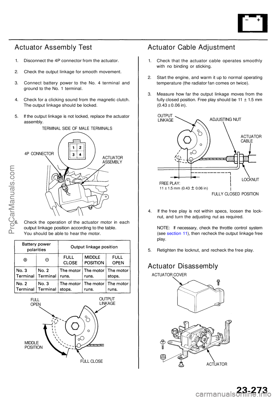
Actuator Assembl y Tes t
1. Disconnec t th e 4 P connecto r fro m th e actuator .
2 . Chec k th e outpu t linkag e fo r smoot h movement .
3 . Connec t batter y powe r t o th e No . 4 termina l an d
groun d t o th e No . 1 terminal .
4 . Chec k fo r a clickin g soun d fro m th e magneti c clutch .
Th e outpu t linkag e shoul d b e locked .
5 . I f th e outpu t linkag e is no t locked , replac e th e actuato r
assembly .
TERMINA L SID E O F MAL E TERMINAL S
4 P CONNECTO R
ACTUATOR
ASSEMBL Y
6. Chec k th e operatio n o f th e actuato r moto r i n eac h
outpu t linkag e positio n accordin g to th e table .
You shoul d b e abl e t o hea r th e motor .
OUTPU TLINKAG E
MIDDLEPOSITIO N
FULL CLOS E
Actuato r Cabl e Adjustmen t
1. Chec k tha t th e actuato r cabl e operate s smoothl y
wit h n o bindin g o r sticking .
2 . Star t th e engine , an d war m it u p to norma l operatin g
temperatur e (th e radiato r fa n come s o n twice) .
3 . Measur e ho w fa r th e outpu t linkag e move s fro m th e
full y close d position . Fre e pla y shoul d b e 1 1 ± 1. 5 m m
(0.4 3 ± 0.0 6 in) .
OUTPU T
LINKAG EADJUSTIN G NU T
ACTUATO RCABLE
4. I f th e fre e pla y i s no t withi n specs , loose n th e lock -
nut , an d tur n th e adjustin g nu t a s required .
NOTE : I f necessary , chec k th e throttl e contro l syste m
(se e sectio n 11 ), the n rechec k th e outpu t linkag e fre e
play .
5. Retighte n th e locknut , an d rechec k th e fre e play .
Actuato r Disassembl y
ACTUATOR COVE R
ACTUATO R
FULL
OPE N FULL
Y CLOSE D POSITIO N
LOCKNU
T
FRE E PLAY :
11 ± 1. 5 m m (0.4 3 ± 0.06 in)
ProCarManuals.com