1995 ACURA TL engine
[x] Cancel search: enginePage 1312 of 1771
Modulator Uni t
Removal/Installatio n (cont'd )
Installation :
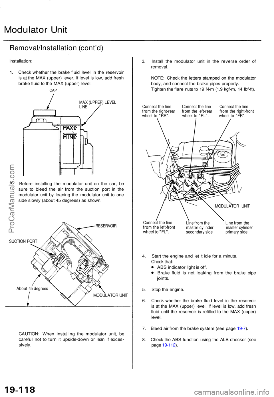
1 . Chec k whethe r th e brak e flui d leve l i n th e reservoi r
i s a t th e MA X (upper ) lever . I f leve l i s low , ad d fres h
brak e flui d t o th e MA X (upper ) level .
CAP
MA X (UPPER ) LEVE L
LIN E
2. Befor e installin g th e modulato r uni t o n th e car , b e
sur e t o blee d th e ai r fro m th e suctio n por t i n th e
modulato r uni t b y leanin g th e modulato r uni t t o on e
sid e slowl y (abou t 4 5 degrees ) a s shown .
RESERVOI R
SUCTION POR T
Abou t 4 5 degree s
MODULATO R UNI T
CAUTION : Whe n installin g th e modulato r unit , b e
carefu l no t t o tur n i t upside-dow n o r lea n i f exces -
sively.
3. Instal l th e modulato r uni t i n th e revers e orde r o f
removal .
NOTE : Chec k th e letter s stampe d o n th e modulato r
body , an d connec t th e brak e pipe s properly .
Tighte n th e flar e nut s t o 1 9 N- m (1. 9 kgf-m , 1 4 Ibf-ft) .
Connec t th e lin e Connec t th e lin e Connec t th e lin e
fro m th e right-rea r fro m th e left-rea r fro m th e right-fron t
whee l t o "RR" . whee l t o "RL" . whee l t o "FR" .
Connec t th e lin e
fro m th e left-fron t
wheel t o "FL" .
MODULATO R UNI T
Lin e fro m th e Lin e fro m th e
maste r cylinde r maste r cylinde r
secondar y sid e primar y sid e
4. Star t th e engine and le t i t idl e fo r a minute .
Chec k that :
ABS indicato r ligh t i s off .
Brak e flui d i s no t leakin g fro m th e brak e pip e
joints .
5. Sto p th e engine .
6 . Chec k whethe r th e brak e flui d leve l i n th e reservoi r
i s a t th e MA X (upper ) level . I f leve l i s low , ad d fres h
flui d unti l th e reservoi r i s refille d t o th e MA X (upper )
level.
7. Blee d ai r fro m th e brak e syste m (se e pag e 19-7 ).
8 . Chec k th e AB S functio n usin g th e AL B checke r (se e
pag e 19-112 ).
ProCarManuals.com
Page 1316 of 1771
3. Remov e th e modulato r uni t fro m th e ca r (se e pag e
19-117 ).
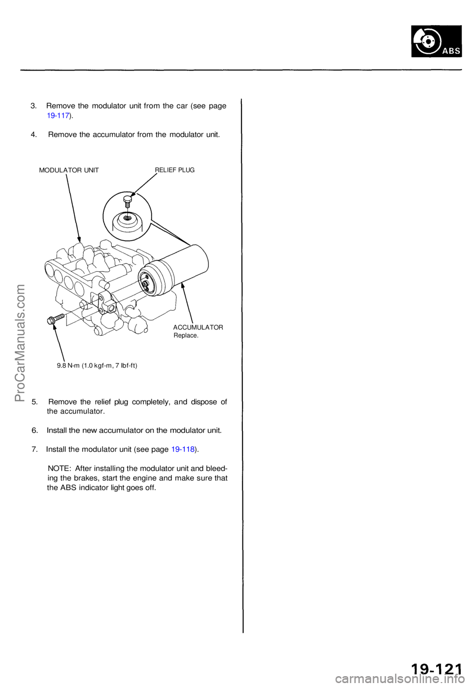
4 . Remov e th e accumulato r fro m th e modulato r unit .
MODULATO R UNI TRELIE F PLU G
ACCUMULATO RReplace.
9.8 N- m (1. 0 kgf-m , 7 Ibf-ft )
5. Remov e th e relie f plu g completely , an d dispos e o f
the accumulator .
6. Instal l th e ne w accumulato r o n th e modulato r unit .
7. Instal l th e modulato r uni t (se e pag e 19-118 ).
NOTE : Afte r installin g th e modulato r uni t an d bleed -
in g th e brakes , star t th e engine and mak e sur e tha t
th e AB S indicato r ligh t goe s off .
ProCarManuals.com
Page 1330 of 1771
Troubleshooting Precautions
ABS Indicator Light
1. If the system is OK, the ABS indicator light goes off two seconds after turning the ignition switch ON (II) without start-
ing the engine. After starting the engine, the ABS indicator light comes on again and goes off after two seconds. This
occurs because the ABS control unit is activated by the IG2 power source.
2. The ABS indicator light comes on when the ABS control unit detects a problem in the system. However, even though
the system is normal, the ABS indicator light comes on, too, under the following conditions. To determine the actual
cause of problem, question the customer about the problem, talking the following conditions into consideration.
Only drive wheels rotate
One wheel stuck of drive wheels
Vehicle spin
ABS operate condition continue for long time
Signal disturbance
3. When a problem is detected and the ABS indicator light comes on, there are cases when the indicator light stays on
until the ignition switch is turned OFF, and cases when the indicator light goes off automatically when the system
returns normal. For the DTC 61 and 62, the indicator light goes off automatically when the system returns normal. For
all other codes, the indicator light stays on until the ignition switch is turned OFF.
4. For DTCs 12, 14, 16, 18, 21, 22, 23, 24, 51, 52 and 53, the indicator light goes off when the vehicle is driven again and
the signals are OK after the ignition switch is turned from OFF to ON (II). However, if the DTC is erased, the CPU is
reset and the indicator light goes off right after the engine is started if the signals are OK.
Diagnostic Trouble Code (DTC)
1. The DTC is not memorized if the CPU cannot be activated or the CPU fails and the indicator light comes on.
2. The memory can hold any number of DTCs. However, when the same DTC is detected more than once, the later one
is written over the old one. Therefore, when the same problem is detected repeatedly, it is memorized as one DTC.
3. The DTCs are indicated in the order of ascending number, not in the order they occur.
4. The DTCs are memorized in the EEPROM (non-volatile memory). Therefore, the memorized DTCs cannot be canceled
by disconnecting the battery. Perform the specified procedures to erase the DTCs.
Self-diagnosis
1. The self-diagnosis can be classified into two categories.
Initial diagnosis: Performed right after the engine starts and until the ABS indicator light goes off.
Regular diagnosis: Performed right after the initial diagnosis until the ignition switch is turned OFF.
2. When a problem is detected by self-diagnosis, the system
Turns the ABS indicator light ON
Memorizes the DTC
Turns the fail-safe relay OFF
Stops ABS controlProCarManuals.com
Page 1335 of 1771
Modulator Unit
Removal/Installation
CAUTION:
Do not spill brake fluid on the vehicle; it may damage the paint; if brake fluid does contact the paint, wash it off
immediately with water.
Take care not to damage or deform the brake lines during removal and installation.
To prevent the brake fluid from flowing, plug and cover the hose ends and joints with a shop towel or equivalent
material.
NOTE: Tighten the flare nuts to 15 N-m (1.5 kgf-m, 11 Ibf-ft).
Removal
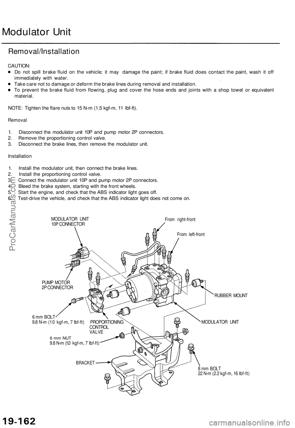
1. Disconnect the modulator unit 10P and pump motor 2P connectors.
2. Remove the proportioning control valve.
3. Disconnect the brake lines, then remove the modulator unit.
Installation
1. Install the modulator unit, then connect the brake lines.
2. Install the proportioning control valve.
3. Connect the modulator unit 10P and pump motor 2P connectors.
4. Bleed the brake system, starting with the front wheels.
5. Start the engine, and check that the ABS indicator light goes off.
6. Test-drive the vehicle, and check that the ABS indicator light does not come on.
MODULATOR UNIT
10P CONNECTOR
From right-front
From left-front
PUMP MOTOR
2P CONNECTOR
6 mm BOLT
9.8 N-m (1 .0 kgf-m, 7 Ibf-ft) PROPORTIONING
CONTROL
VALVE
6 mm NUT
9.8 N-m (1.0 kgf-m, 7 Ibf-ft)
BRACKET
RUBBER MOUNT
MODULATOR UNIT
8 mm BOLT
22 N-m (2.2 kgf-m, 16 Ibf-ft)ProCarManuals.com
Page 1497 of 1771
Troubleshooting
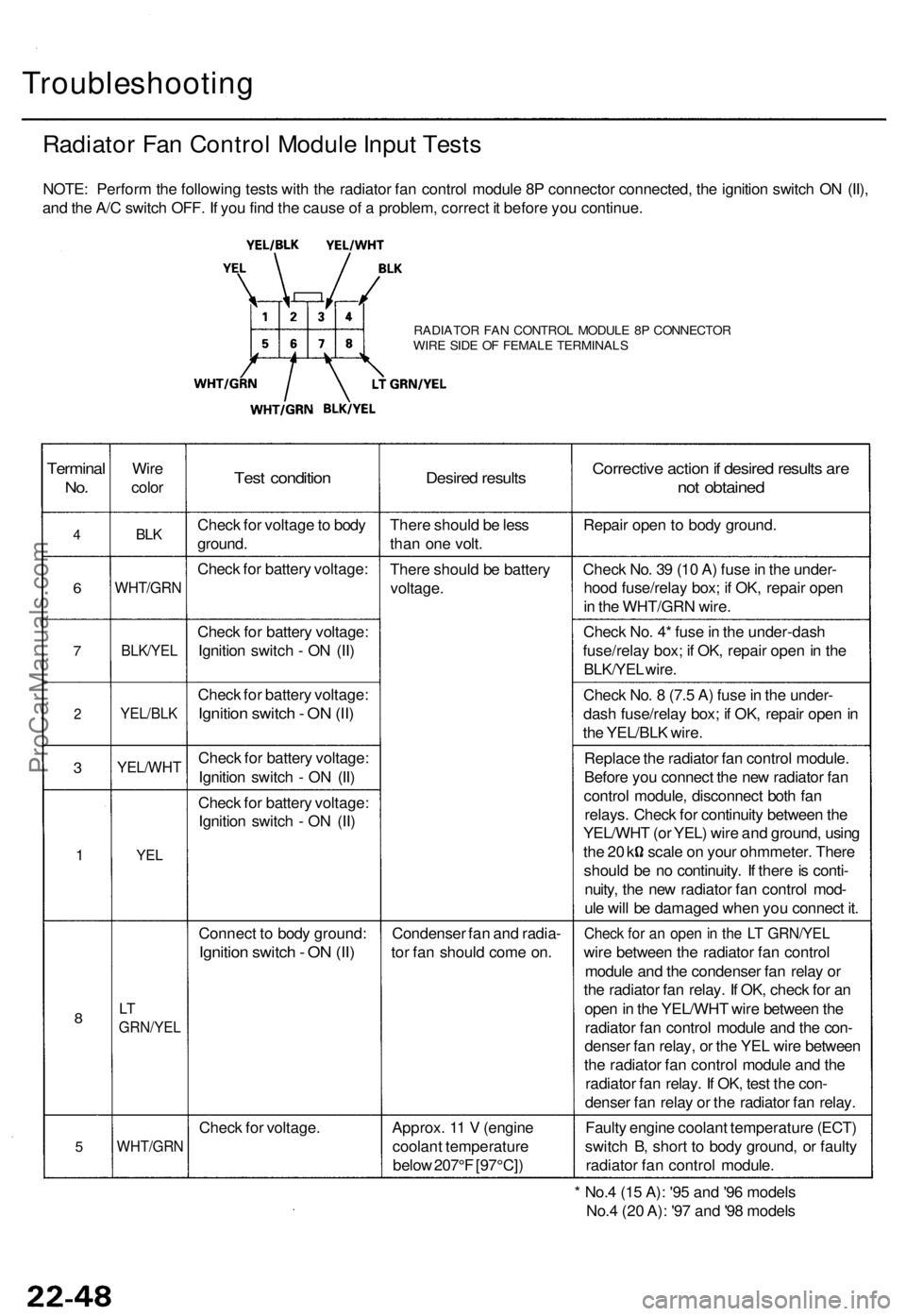
Radiator Fan Control Module Input Tests
NOTE: Perform the following tests with the radiator fan control module 8P connector connected, the ignition switch ON (II),
and the A/C switch OFF. If you find the cause of a problem, correct it before you continue.
RADIATOR FAN CONTROL MODULE 8P CONNECTOR
WIRE SIDE OF FEMALE TERMINALS
Terminal
No.
4
6
7
2
3
1
8
5
Wire
color
BLK
WHT/GRN
BLK/YEL
YEL/BLK
YEL/WHT
YEL
LT
GRN/YEL
WHT/GRN
Test condition
Check for voltage to body
ground.
Check for battery voltage:
Check for battery voltage:
Ignition switch - ON (II)
Check for battery voltage:
Ignition switch - ON (II)
Check for battery voltage:
Ignition switch - ON (II)
Check for battery voltage:
Ignition switch - ON (II)
Connect to body ground:
Ignition switch - ON (II)
Check for voltage.
Desired results
There should be less
than one volt.
There should be battery
voltage.
Condenser fan and radia-
tor fan should come on.
Approx. 11 V (engine
coolant temperature
below 207°F [97°C])
Corrective action if desired results are
not obtained
Repair open to body ground.
Check No. 39 (10 A) fuse in the under-
hood fuse/relay box; if OK, repair open
in the WHT/GRN wire.
Check No. 4* fuse in the under-dash
fuse/relay box; if OK, repair open in the
BLK/YEL wire.
Check No. 8 (7.5 A) fuse in the under-
dash fuse/relay box; if OK, repair open in
the YEL/BLK wire.
Replace the radiator fan control module.
Before you connect the new radiator fan
control module, disconnect both fan
relays. Check for continuity between the
YEL/WHT (or YEL) wire and ground, using
the 20 k scale on your ohmmeter. There
should be no continuity. If there is conti-
nuity, the new radiator fan control mod-
ule will be damaged when you connect it.
Check for an open in the LT GRN/YEL
wire between the radiator fan control
module and the condenser fan relay or
the radiator fan relay. If OK, check for an
open in the YEL/WHT wire between the
radiator fan control module and the con-
denser fan relay, or the YEL wire between
the radiator fan control module and the
radiator fan relay. If OK, test the con-
denser fan relay or the radiator fan relay.
Faulty engine coolant temperature (ECT)
switch B, short to body ground, or faulty
radiator fan control module.
* No.4 (15 A): '95 and '96 models
No.4 (20 A): '97 and '98 modelsProCarManuals.com
Page 1514 of 1771
Heater Uni t
Replacemen t (cont'd )
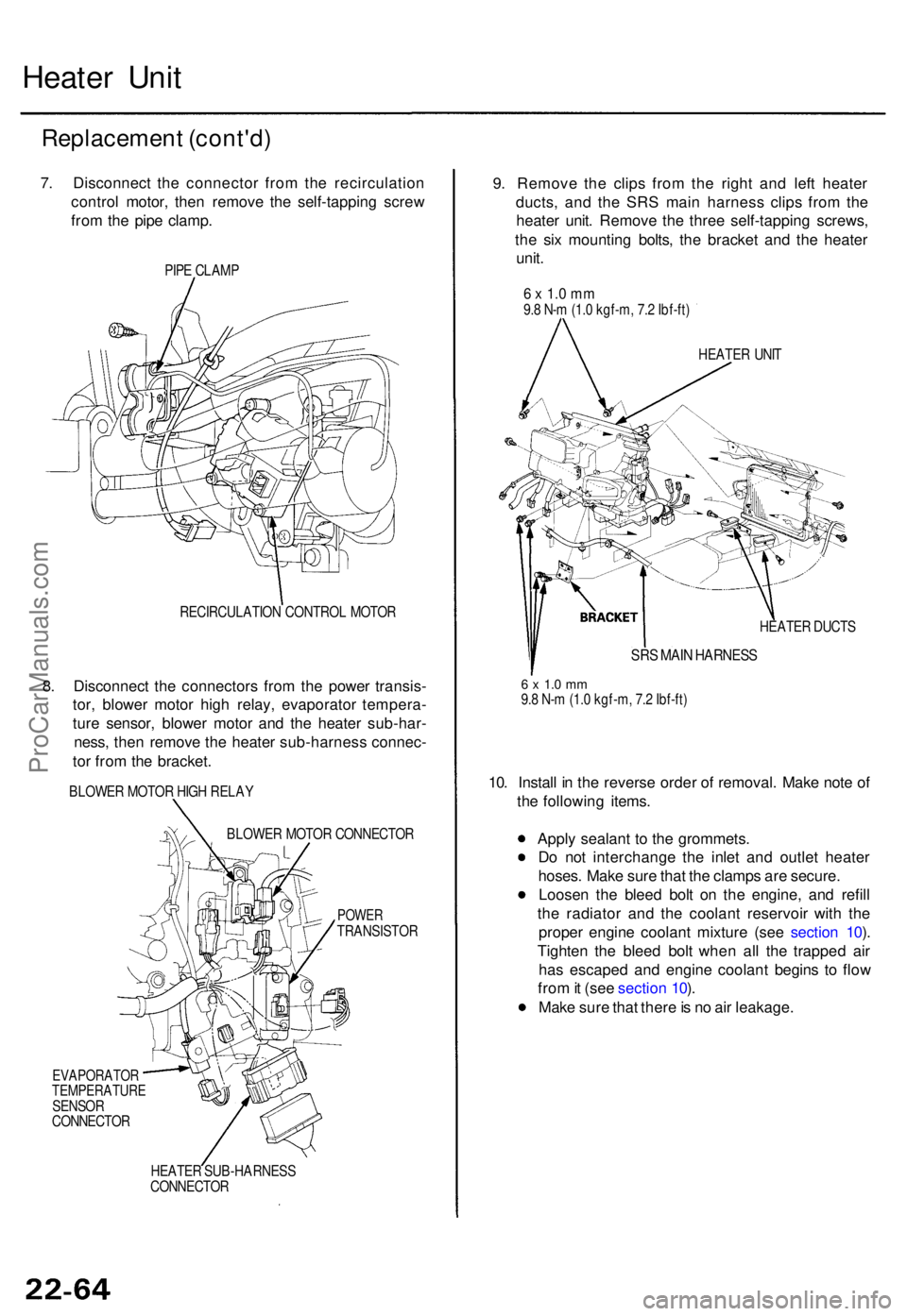
7. Disconnec t th e connecto r fro m th e recirculatio n
contro l motor , the n remov e th e self-tappin g scre w
fro m th e pip e clamp .
PIPE CLAM P
RECIRCULATIO N CONTRO L MOTO R
8. Disconnec t th e connector s fro m th e powe r transis -
tor , blowe r moto r hig h relay , evaporato r tempera -
tur e sensor , blowe r moto r an d th e heate r sub-har -
ness , the n remov e th e heate r sub-harnes s connec -
to r fro m th e bracket .
BLOWER MOTO R HIG H RELA Y
BLOWE R MOTO R CONNECTO R
POWERTRANSISTO R
EVAPORATO RTEMPERATUR ESENSORCONNECTO R
HEATE R SUB-HARNES S
CONNECTO R
9. Remov e th e clip s fro m th e righ t an d lef t heate r
ducts , an d th e SR S mai n harnes s clip s fro m th e
heate r unit . Remov e th e thre e self-tappin g screws,
th e si x mountin g bolts , th e bracke t an d th e heate r
unit .
6 x 1. 0 m m9.8 N- m (1. 0 kgf-m , 7. 2 Ibf-ft )
HEATE R UNI T
HEATE R DUCT S
SRS MAI N HARNES S
6 x 1. 0 m m9.8 N- m (1. 0 kgf-m , 7. 2 Ibf-ft )
10. Instal l i n th e revers e orde r o f removal . Mak e not e o f
th e followin g items .
Appl y sealan t t o th e grommets .
D o no t interchang e th e inle t an d outle t heate r
hoses . Mak e sur e tha t th e clamp s ar e secure .
Loose n th e blee d bol t o n th e engine , an d refil l
th e radiato r an d th e coolan t reservoi r wit h th e
prope r engin e coolan t mixtur e (se e sectio n 10 ).
Tighte n th e blee d bol t whe n al l th e trappe d ai r
ha s escape d an d engin e coolan t begin s t o flo w
fro m it (se e sectio n 10 ).
Mak e sur e tha t ther e is n o ai r leakage .
ProCarManuals.com
Page 1536 of 1771

Troubleshooting
Tips and Precautions
Before Troubleshooting
Check applicable fuses in the appropriate fuse/relay
box.
Check the battery for damage, state of charge, and
clean and tight connections.
Check the alternator belt tension.
CAUTION:
Do not quick-charge a battery unless the battery
ground cable has been disconnected, otherwise you
will damage the alternator diodes.
Do not attempt to crank the engine with the battery
ground cable loosely connected or you will severely
damage the wiring.
Handling Connectors
Make sure the connectors are clean and have no loose
wire terminals.
Make sure multiple cavity connectors are packed with
grease (except waterproof connectors).
All connectors have push-down release type locks.
LOCKING TAB
Some connectors have a clip on their side used to
attach them to a mount bracket on the body or on
another component. This clip has a pull type lock.
Some mounted connectors cannot be disconnected
unless you first release the lock and remove the con-
nector from its mount bracket.
LOCKING
PAWL ON
OTHER
HALF OF
CONNECTOR
Pull to
disengage
BRACKET
Never try to disconnect connectors by pulling on
their wires; pull on the connector halves instead.
Always reinstall plastic covers.
Before connecting connectors, make sure the termi-
nals are in place and not bent.
BENT TERMINAL
Check for loose retainer and rubber seals.
RETAINER
RUBBER SEAL RETAINER
The backs of some connectors are packed with
grease. Add grease if necessary. If the grease is con-
taminated, replace it.
LOCKING TABProCarManuals.com
Page 1539 of 1771
Relay and Control Unit Locations
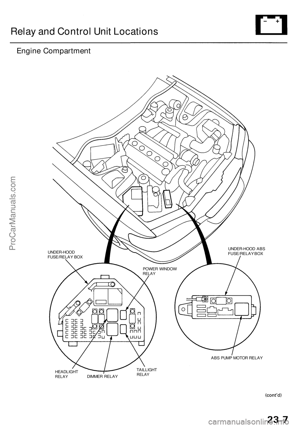
Engine Compartment
UNDER-HOOD ABS
FUSE/RELAY BOX
ABS PUMP MOTOR RELAY
HEADLIGHT
RELAY
DIMMER RELAY
TAILLIGHT
RELAY
POWER WINDOW
RELAY
UNDER-HOOD
FUSE/RELAY BOXProCarManuals.com