1995 ACURA TL engine
[x] Cancel search: enginePage 1162 of 1771
Inspection an d Adjustmen t
Steering Operatio n
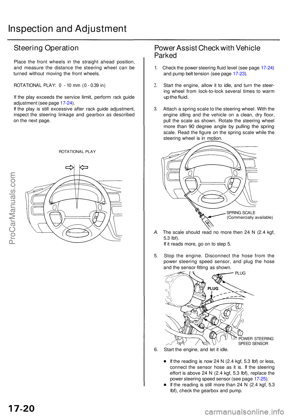
Place th e fron t wheel s i n th e straigh t ahea d position ,
an d measur e th e distanc e th e steerin g whee l ca n b e
turne d withou t movin g th e fron t wheels .
ROTATIONA L PLAY : 0 - 10 m m (0 - 0.3 9 in )
If th e pla y exceed s the servic e limit, perfor m rack guid e
adjustmen t (se e pag e 17-24 ).
I f th e pla y i s stil l excessiv e afte r rac k guid e adjustment ,
inspec t th e steerin g linkag e an d gearbo x a s describe d
o n th e nex t page .
ROTATIONA L PLA Y
Powe r Assis t Chec k wit h Vehicl e
Parked
1. Chec k th e powe r steerin g flui d leve l (se e pag e 17-24 )
an d pum p bel t tensio n (se e pag e 17-23 ).
2 .
3 .
Star t th e engine , allo w it t o idle , an d tur n th e steer -
in g whee l fro m lock-to-loc k severa l time s t o war m
up th e fluid .
Attac h a sprin g scal e to th e steerin g wheel . Wit h th e
engin e idlin g an d th e vehicl e o n a clean , dr y floor ,
pul l th e scal e a s shown . Rotat e th e steerin g whee l
more tha n 9 0 degre e angl e b y pullin g th e sprin g
scale. Rea d th e figur e o n th e sprin g scal e whil e th e
steerin g whee l i s i n motion .
SPRING SCAL E(Commerciall y available )
A. Th e scal e shoul d rea d n o mor e the n 2 4 N (2. 4 kgf ,
5.3 Ibf) .
If i t read s more , g o o n t o ste p 5 .
5 . Sto p th e engine . Disconnec t th e hos e fro m th e
powe r steerin g spee d sensor , an d plu g th e hos e
an d th e senso r fittin g a s shown .
PLUG
POWE R STEERIN GSPEED SENSO R
6. Star t th e engine , an d le t i t idle .
I f th e readin g is no w 2 4 N (2. 4 kgf , 5. 3 Ibf ) o r less ,
connec t th e senso r hos e a s i t is . I f th e steerin g
effor t i s abov e 2 4 N (2. 4 kgf , 5. 3 Ibf) , replac e th e
powe r steerin g spee d senso r (se e pag e 17-25 ).
I f th e readin g i s stil l mor e tha n 2 4 N (2. 4 kgf , 5. 3
Ibf) , chec k th e gearbo x an d pump .
ProCarManuals.com
Page 1163 of 1771
Assist Chec k a t Roa d Spee d
1. Chec k th e powe r steerin g flui d leve l (se e pag e 17-24 ),
an d chec k th e pum p bel t tensio n (se e pag e 17-23 ).
2 .
3 .
Star t th e engine , le t i t war m u p t o norma l operatin g
temperature , an d tur n th e steerin g whee l lock-to-loc k
a fe w time s t o war m u p th e fluid .
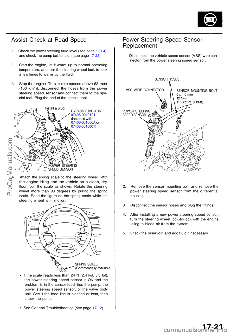
Stop th e engine . T o simulat e speed s abov e 6 2 mp h
(100 km/h) , disconnec t th e hose s fro m th e powe r
steerin g spee d senso r an d connec t the m to th e spe -
cia l tool . Plu g th e en d o f th e specia l tool .
Instal l a plug .
BYPAS S TUB E JOIN T07406-001010 1(Included wit h07406-001000 A or07406-0010001 )
POWER STEERIN GSPEED SENSO R
4. Attac h th e sprin g scal e t o th e steerin g wheel . Wit h
the engin e idlin g an d th e vehicl e o n a clean , dr y
floor , pul l th e scal e a s shown . Rotat e th e steerin g
whee l mor e tha n 9 0 degree s b y pullin g th e sprin g
scale . Rea d th e figur e o n th e sprin g scal e whil e th e
steerin g whee l i s i n motion .
SPRING SCAL E(Commerciall y available )
• I f th e scal e read s les s tha n 2 4 N (2. 4 kgf , 5. 3 Ibf) ,
th e powe r steerin g spee d senso r i s O K an d th e
proble m is i n th e senso r fee d line , th e pump , th e
powe r steerin g spee d sensor , o r th e valv e bod y
unit . Se e i f th e fee d lin e i s pinche d o r bent , the n
chec k th e pump .
• Se e Genera l Troubleshootin g (se e pag e 17-12 ).
Powe r Steerin g Spee d Senso r
Replacemen t
1. Disconnec t th e vehicl e spee d senso r (VSS ) wir e con -
necto r fro m th e powe r steerin g spee d sensor .
SENSO R HOSE S
VSS WIR E CONNECTO R
POWER STEERIN GSPEED SENSO R
SENSOR MOUNTIN G BOL T6 x 1. 0 m m12 N- m11.2 kgf-m , 9 Ibf-ft )
2. Remov e th e senso r mountin g bolt , an d remov e th e
powe r steerin g spee d senso r fro m th e differentia l
housing .
3 . Disconnec t th e senso r hose s an d plu g th e fittings .
4 . Afte r installin g a ne w powe r steerin g spee d sensor ,
tur n th e steerin g whee l lock-to-loc k wit h th e engin e
idlin g t o blee d ai r fro m th e system .
5 . Chec k th e reservoir , an d ad d flui d if necessary .
ProCarManuals.com
Page 1166 of 1771
Inspection an d Adjustmen t
Rack Guid e Adjustmen t
NOTE: Perfor m rac k guid e adjustmen t wit h th e wheel s
i n th e straigh t ahea d position .
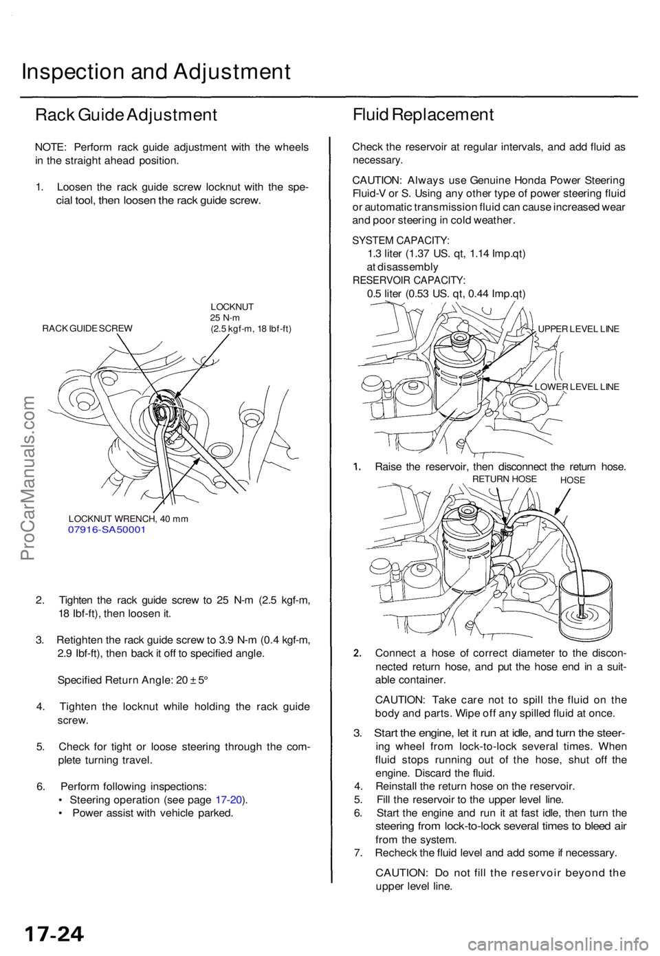
1 . Loose n th e rac k guid e scre w locknu t wit h th e spe -
cial tool , the n loose n th e rac k guid e screw .
Fluid Replacemen t
RACK GUID E SCRE W
LOCKNU T25 N- m(2.5 kgf-m , 1 8 Ibf-ft )
LOCKNU T WRENCH , 4 0 m m
07916-SA50001
2. Tighte n th e rac k guid e scre w to 2 5 N- m (2. 5 kgf-m ,
1 8 Ibf-ft) , the n loose n it .
3 . Retighte n th e rac k guid e scre w to 3. 9 N- m (0. 4 kgf-m ,
2. 9 Ibf-ft) , the n bac k it of f t o specifie d angle .
Specifie d Retur n Angle : 2 0 ± 5°
4 . Tighte n th e locknu t whil e holdin g th e rac k guid e
screw .
5. Chec k fo r tigh t o r loos e steerin g throug h th e com -
plet e turnin g travel .
6 . Perfor m followin g inspections :
• Steerin g operatio n (se e pag e 17-20 ).
• Powe r assis t wit h vehicl e parked . Chec
k th e reservoi r a t regula r intervals , an d ad d flui d a s
necessary .
CAUTION: Alway s us e Genuin e Hond a Powe r Steerin g
Fluid- V o r S . Usin g an y othe r typ e o f powe r steerin g flui d
o r automati c transmissio n flui d ca n caus e increase d wea r
an d poo r steerin g in col d weather .
SYSTEM CAPACITY :
1.3 lite r (1.3 7 US . qt , 1.1 4 Imp.qt )
a t disassembl y
RESERVOIR CAPACITY :
0.5 lite r (0.5 3 US . qt , 0.4 4 Imp.qt )
UPPER LEVE L LIN E
LOWE R LEVE L LIN E
Rais e th e reservoir , the n disconnec t th e retur n hose .RETUR N HOS E HOSE
Connect a hos e o f correc t diamete r t o th e discon -
necte d retur n hose , an d pu t th e hos e en d i n a suit -
abl e container .
CAUTION : Tak e car e no t t o spil l th e flui d o n th e
bod y an d parts . Wip e of f an y spille d flui d a t once .
3. Star t th e engine , le t i t ru n a t idle , an d tur n th e steer -
ing whee l fro m lock-to-loc k severa l times . Whe n
flui d stop s runnin g ou t o f th e hose , shu t of f th e
engine . Discar d th e fluid .
4 . Reinstal l th e retur n hos e o n th e reservoir .
5 . Fil l th e reservoi r t o th e uppe r leve l line .
6 . Star t th e engin e an d ru n i t a t fas t idle , the n tur n th e
steerin g fro m lock-to-loc k severa l time s t o blee d ai r
fro m th e system .
7 . Rechec k th e flui d leve l an d ad d som e if necessary .
CAUTION: D o no t fil l th e reservoi r beyon d th e
uppe r leve l line .
ProCarManuals.com
Page 1167 of 1771
Pump Pressur e Chec k
Chec k th e flui d pressur e a s follow s t o determin e
whethe r th e troubl e i s i n th e pum p o r gearbox .
NOTE : Firs t chec k th e powe r steerin g flui d leve l an d
pum p bel t tension .
CAUTION : Disconnec t th e hig h pressur e hos e wit h car e
s o a s no t t o spil l th e powe r steerin g flui d o n th e fram e
an d othe r parts .
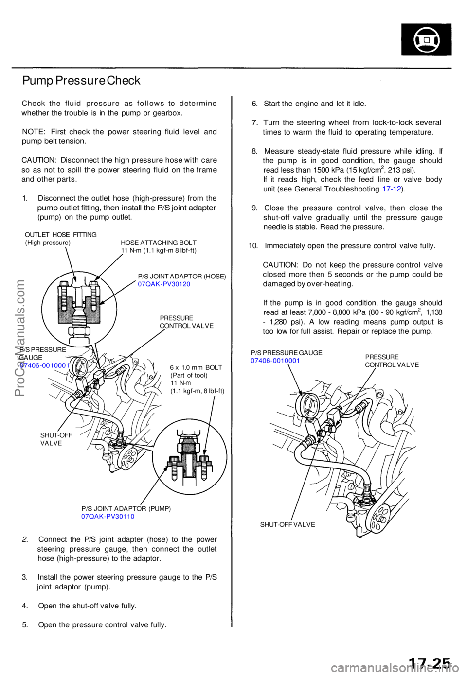
1 . Disconnec t th e outle t hos e (high-pressure ) fro m th e
pum p outle t fitting , the n instal l th e P/ S join t adapte r
(pump) o n th e pum p outlet .
OUTLE T HOS E FITTIN G
(High-pressure )
P/ S PRESSUR E
GAUG E
07406-001000 1
HOSE ATTACHIN G BOL T
1 1 N- m (1. 1 kgf- m 8 Ibf-ft )
P/ S JOIN T ADAPTO R (HOSE )
07QAK-PV3012 0
PRESSURECONTROL VALV E
6 x 1. 0 m m BOL T
(Par t o f tool )
11 N- m(1.1 kgf-m , 8 Ibf-ft )
SHUT-OF F
VALVE
P/S JOIN T ADAPTO R (PUMP )
07QAK-PV3011 0
2. Connec t th e P/ S join t adapte r (hose ) t o th e powe r
steerin g pressur e gauge , the n connec t th e outle t
hos e (high-pressure ) t o th e adaptor .
3 . Instal l th e powe r steerin g pressur e gaug e t o th e P/ S
join t adapto r (pump) .
4 . Ope n th e shut-of f valv e fully .
5 . Ope n th e pressur e contro l valv e fully . 6
. Star t th e engine and le t i t idle .
7. Tur n th e steerin g whee l fro m lock-to-loc k severa l
times t o war m th e flui d t o operating temperature .
8 . Measur e steady-stat e flui d pressur e whil e idling . I f
th e pum p i s i n goo d condition , th e gaug e shoul d
rea d les s tha n 150 0 kP a (1 5 kgf/cm
2, 21 3 psi) .
I f i t read s high , chec k th e fee d lin e o r valv e bod y
uni t (se e Genera l Troubleshootin g 17-12 ).
9 . Clos e th e pressur e contro l valve , the n clos e th e
shut-of f valv e graduall y unti l th e pressur e gaug e
needl e is stable . Rea d th e pressure .
10 . Immediatel y ope n th e pressur e contro l valv e fully .
CAUTION : D o no t kee p th e pressur e contro l valv e
close d mor e the n 5 second s o r th e pum p coul d b e
damage d b y over-heating .
I f th e pum p i s i n goo d condition , th e gaug e shoul d
rea d a t leas t 7,80 0 - 8,80 0 kP a (8 0 - 9 0 kgf/cm
2, 1,13 8
- 1,28 0 psi) . A lo w readin g mean s pum p outpu t i s
to o lo w fo r ful l assist . Repai r o r replac e th e pump .
P/S PRESSUR E GAUG E07406-001000 1 PRESSUR ECONTROL VALV E
SHUT-OF F VALV E
ProCarManuals.com
Page 1190 of 1771
Power Steerin g Pum p
Installatio n
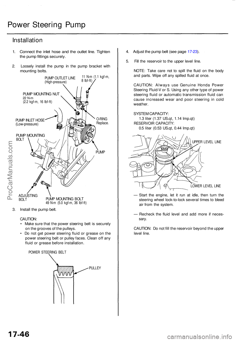
1. Connec t th e inle t hos e an d th e outle t line . Tighte n
the pum p fitting s securely .
2. Loosel y instal l th e pum p i n th e pum p bracke t wit h
mountin g bolts .
ADJUSTIN GBOLT
PUM P MOUNTIN G NU T22 N- m(2.2 kgf-m , 1 6 Ibf-ft )
PUMP INLE T HOS E(Low-pressure )
PUMP MOUNTIN GBOLT O-RIN
G
Replace .
PUMP
PUMP MOUNTIN G BOL T49 N- m (5. 0 kgf-m , 3 6 Ibf-ft )
3. Instal l th e pum p belt .
CAUTION :
• Mak e sur e tha t th e powe r steerin g bel t i s securel y
o n th e groove s o f th e pulleys .
• D o no t ge t powe r steerin g flui d o r greas e o n th e
powe r steerin g bel t o r pulle y faces . Clea n of f an y
flui d o r greas e befor e installation .
POWER STEERIN G BEL T
PULLEY
4. Adjus t th e pum p bel t (se e pag e 17-23 ).
5 . Fil l th e reservoi r t o th e uppe r leve l line .
NOTE : Tak e car e no t t o spil l th e flui d o n th e bod y
an d parts . Wip e of f an y spille d flui d a t once .
CAUTION : Alway s us e Genuin e Hond a Powe r
Steerin g Fluid- V o r S . Usin g an y othe r typ e o f powe r
steerin g flui d o r automati c transmissio n flui d ca n
caus e increase d wea r an d poo r steerin g i n col d
weather .
SYSTE M CAPACITY :
1. 3 lite r (1.3 7 US.qt , 1.1 4 Imp.qt )
RESERVOI R CAPACITY :
0.5 lite r (0.5 3 US.qt , 0.4 4 Imp.qt )
UPPER LEVE L LIN E
LOWE R LEVE L LIN E
— Star t th e engine , le t i t ru n a t idle , the n tur n th e
steerin g whee l lock-to-loc k severa l time s t o blee d
ai r fro m th e system .
— Rechec k th e flui d leve l an d ad d mor e i f neces -
sary .
CAUTION : D o no t fil l th e reservoi r beyon d th e uppe r
leve l line .
PUM P OUTLE T LIN E(High-pressure )1
1 N- m (1. 1 kgf-m ,
8 Ibf-ft )
ProCarManuals.com
Page 1213 of 1771
Steering Gearbo x
Installatio n (cont'd )
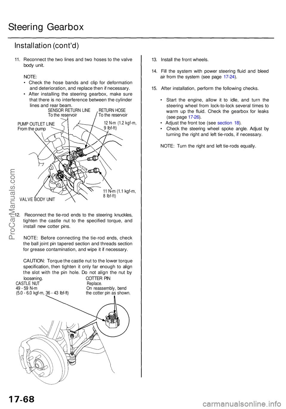
11. Reconnec t th e tw o line s an d tw o hose s t o th e valv e
body unit .
NOTE :
• Chec k th e hos e band s an d cli p fo r deformatio n
an d deterioration , an d replac e the n if necessary .
• Afte r installin g th e steerin g gearbox , mak e sur e
tha t ther e is n o interferenc e betwee n th e cylinde r
line s an d rea r beam .
PUMP OUTLE T LIN EFrom th e pum p
12 N- m (1. 2 kgf-m ,9 Ibf-ft )
VALV E BOD Y UNI T
11 N- m (1. 1 kgf-m ,8 Ibf-ft )
12. Reconnec t th e tie-ro d end s t o th e steerin g knuckles ,
tighte n th e castl e nu t t o th e specifie d torque , an d
instal l ne w cotte r pins .
NOTE : Befor e connectin g th e tie-ro d ends , chec k
th e bal l join t pi n tapere d sectio n an d thread s sectio n
fo r greas e contamination , an d wip e it i f necessary .
CAUTION : Torqu e th e castl e nu t t o th e lowe r torqu e
specification , the n tighte n it onl y fa r enoug h t o alig n
th e slo t wit h th e pi n hole . D o no t alig n th e nu t b y
loosening . COTTER PI NCASTL E NU T Replace.49 - 5 9 N- m O n reassembly , ben d(5.0 - 6. 0 kgf-m , 3 6 - 4 3 Ibf-ft ) th e cotte r pi n a s shown .
13. Instal l th e fron t wheels .
14 . Fil l th e syste m wit h powe r steerin g flui d an d blee d
ai r fro m th e syste m (se e pag e 17-24 ).
15 . Afte r installation , perfor m th e followin g checks .
• Star t th e engine , allo w i t t o idle , an d tur n th e
steerin g whee l fro m lock-to-loc k severa l time s t o
war m u p th e fluid . Chec k th e gearbo x fo r leak s
(se e pag e 17-26 ).
• Adjus t th e fron t to e (se e sectio n 18 ).
• Chec k th e steerin g whee l spok e angle . Adjus t b y
turnin g th e righ t an d lef t tie-rods , i f necessary .
NOTE : Tur n th e righ t an d lef t tie-rod s equally .
SENSO R RETUR N LIN ETo th e reservoi rRETURN HOS ETo th e reservoi r
ProCarManuals.com
Page 1252 of 1771
Inspection an d Adjustmen t
Parking Brak e
Inspectio n
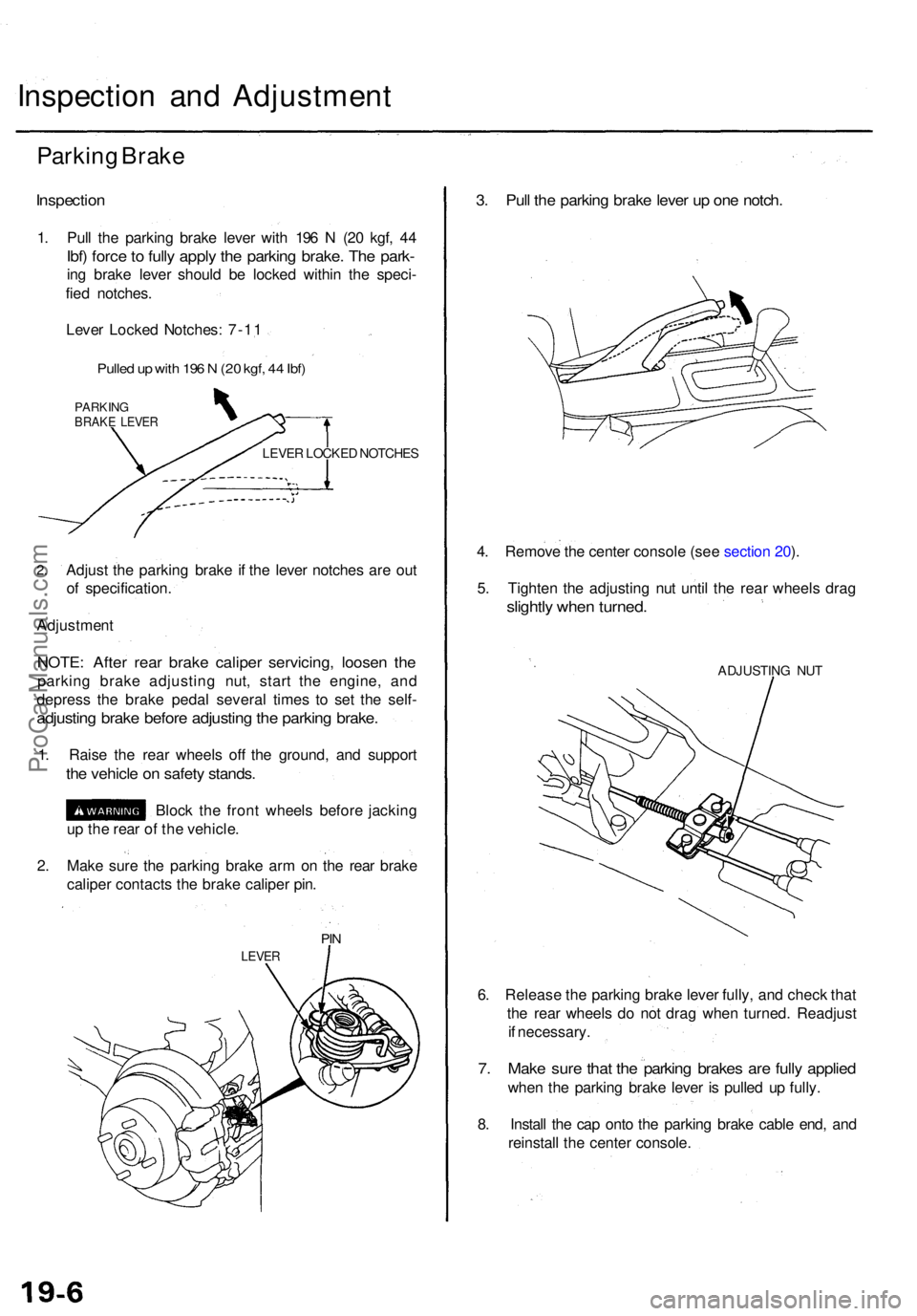
1. Pul l th e parkin g brak e leve r wit h 19 6 N (2 0 kgf , 4 4
Ibf) forc e to full y appl y th e parkin g brake . Th e park -
ing brak e leve r shoul d b e locke d withi n th e speci -
fie d notches .
Leve r Locke d Notches : 7-1 1
Pulle d u p wit h 19 6 N (2 0 kgf , 4 4 Ibf )
PARKIN GBRAKE LEVE R
LEVER LOCKE D NOTCHE S
2.Adjus t th e parkin g brak e i f th e leve r notche s ar e ou t
o f specification .
Adjustmen t
NOTE: Afte r rea r brak e calipe r servicing , loose n th e
parkin g brak e adjustin g nut , star t th e engine , an d
depres s th e brak e peda l severa l time s t o se t th e self -
adjustin g brak e befor e adjustin g th e parkin g brake .
1. Rais e th e rea r wheel s of f th e ground , an d suppor t
the vehicl e o n safet y stands .
Block th e fron t wheel s befor e jackin g
u p th e rea r o f th e vehicle .
2 . Mak e sur e th e parkin g brak e ar m o n th e rea r brak e
calipe r contact s th e brak e calipe r pin .
PIN
LEVE R
3. Pul l th e parkin g brak e leve r u p on e notch .
4. Remov e th e cente r consol e (se e sectio n 20 ).
5 . Tighte n th e adjustin g nu t unti l th e rea r wheel s dra g
slightl y whe n turned .
ADJUSTIN G NU T
6. Releas e th e parkin g brak e leve r fully , an d chec k tha t
th e rea r wheel s d o no t dra g whe n turned . Readjus t
i f necessary .
7. Mak e sur e tha t th e parkin g brake s ar e full y applie d
when th e parkin g brak e leve r i s pulle d u p fully .
8 . Instal l th e ca p ont o th e parkin g brak e cabl e end , an d
reinstal l th e cente r console .
ProCarManuals.com
Page 1263 of 1771
Brake Booster
Inspection
Functional Test
1. With the engine stopped, depress the brake pedal
several times to deplete the vacuum reservoir, then
depress the pedal hard and hold it for 15 seconds. If
the pedal sinks, either the master cylinder is
bypassing internally, or the brake system (master
cylinder, lines, modulator, proportioning valve, or
caliper) is leaking.
2. Start the engine with the pedal depressed. If the
pedal sinks slightly, the vacuum booster is operat-
ing normally. If the pedal height does not vary, the
booster or check valve is faulty.
3. With the engine running, depress the brake pedal
lightly. Apply just enough pressure to hold back
automatic transmission creep. If the brake pedal
sinks more than 25 mm (1.0 in.) in three minutes, the
master cylinder is faulty. A slight change in pedal
height when the A/C compressor cycles on and off if
normal. (The A/C compressor load changes the vac-
uum available to the booster.)
Leak Test
1. Depress the brake pedal with the engine running,
then stop the engine. If the pedal height does not
vary while depressed for 30 seconds, the vacuum
booster is OK. If the pedal rises, the booster is faulty.
2. With the engine stopped, depress the brake pedal
several times using normal pressure. When the
pedal is first depressed, it should be low. On consec-
utive applications, the pedal height should gradually
rise. If the pedal position does not vary, check the
booster check valve.ProCarManuals.com