1995 ACURA TL engine
[x] Cancel search: enginePage 972 of 1771
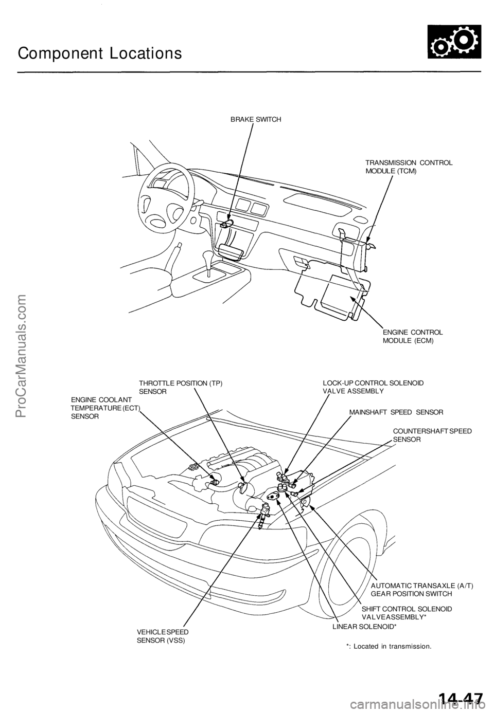
Component Locations
BRAKE SWITCH
TRANSMISSION CONTROL
MODULE (TCM)
ENGINE CONTROL
MODULE (ECM)
THROTTLE POSITION (TP)
SENSOR
ENGINE COOLANT
TEMPERATURE (ECT)
SENSOR
LOCK-UP CONTROL SOLENOID
VALVE ASSEMBLY
MAINSHAFT SPEED SENSOR
COUNTERSHAFT SPEED
SENSOR
VEHICLE SPEED
SENSOR (VSS)
AUTOMATIC TRANSAXLE (A/T)
GEAR POSITION SWITCH
SHIFT CONTROL SOLENOID
VALVE ASSEMBLY*
LINEAR SOLENOID*
*: Located in transmission.ProCarManuals.com
Page 988 of 1771
8.
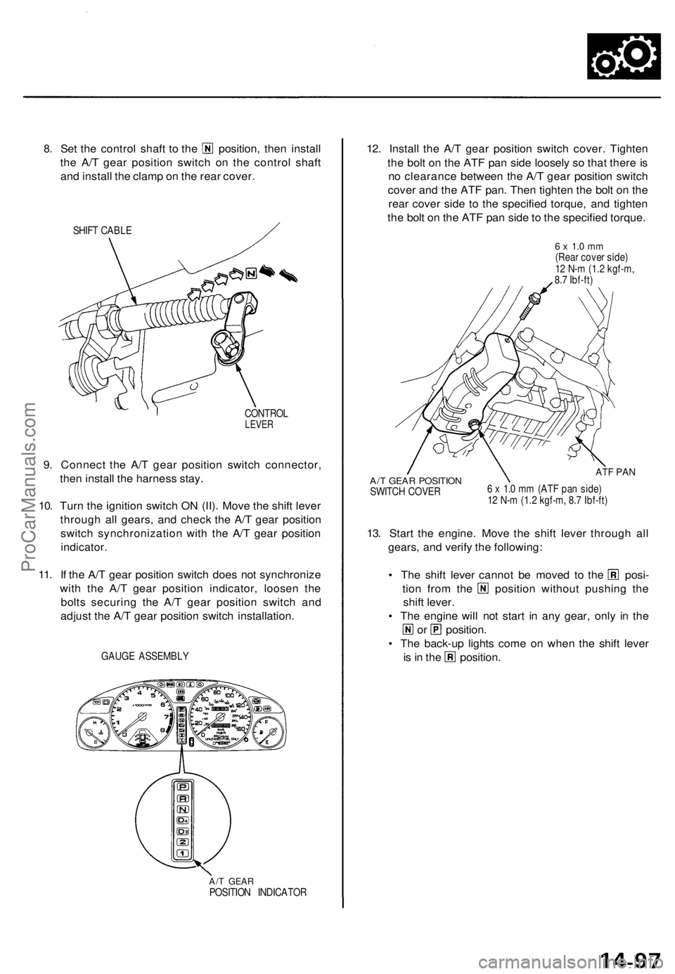
Set the control shaft to the position, then install
the A/T gear position switch on the control shaft
and install the clamp on the rear cover.
SHIFT CABLE
CONTROL
LEVER
9. Connect the A/T gear position switch connector,
then install the harness stay.
10. Turn the ignition switch ON (II). Move the shift lever
through all gears, and check the A/T gear position
switch synchronization with the A/T gear position
indicator.
11. If the A/T gear position switch does not synchronize
with the A/T gear position indicator, loosen the
bolts securing the A/T gear position switch and
adjust the A/T gear position switch installation.
GAUGE ASSEMBLY
A/T GEAR
POSITION INDICATOR
12. Install the A/T gear position switch cover. Tighten
the bolt on the ATF pan side loosely so that there is
no clearance between the A/T gear position switch
cover and the ATF pan. Then tighten the bolt on the
rear cover side to the specified torque, and tighten
the bolt on the ATF pan side to the specified torque.
6 x 1.0 mm
(Rear cover side)
12 N-m (1.2 kgf-m,
8.7 Ibf-ft)
A/T GEAR POSITION
SWITCH COVER
ATF PAN
6 x 1.0 mm (ATF pan side)
12 N-m (1.2 kgf-m, 8.7 Ibf-ft)
13. Start the engine. Move the shift lever through all
gears, and verify the following:
• The shift lever cannot be moved to the posi-
tion from the position without pushing the
shift lever.
• The engine will not start in any gear, only in the
or position.
• The back-up lights come on when the shift lever
is in the position.ProCarManuals.com
Page 993 of 1771
Road Tes t
NOTE : War m u p th e engin e to norma l operatin g temperatur e (th e radiato r fa n come s on) .
1. Appl y parkin g brak e an d bloc k th e wheels . Star t th e engine , the n shif t t o positio n whil e depressin g th e brak e
pedal . Depres s th e accelerato r peda l an d releas e it suddenly . Th e engine should no t stall .
2. Repea t sam e tes t i n position .
3. Shif t t o position , an d chec k tha t th e shif t point s o n a fla t roa d occu r a t th e approximat e speed s show n o n th e nex t
page . Als o chec k fo r abnorma l nois e an d clutc h slippage .
NOTE : Throttl e positio n senso r voltag e represent s th e throttl e opening .
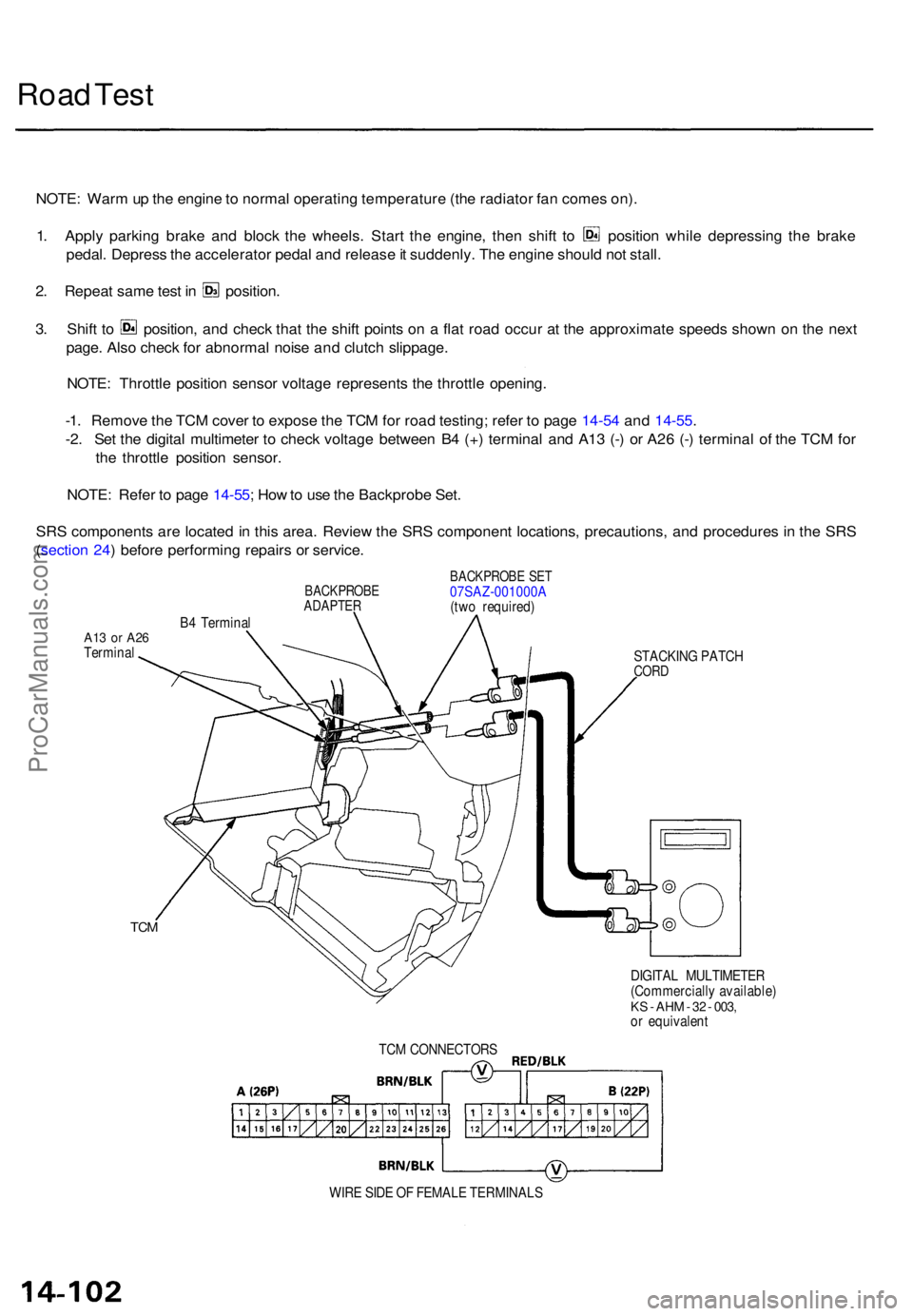
-1 . Remov e th e TC M cove r t o expos e th e TC M fo r roa d testing ; refe r t o pag e 14-5 4 an d 14-55 .
-2 . Se t th e digita l multimete r t o chec k voltag e betwee n B 4 (+ ) termina l an d A1 3 (- ) o r A2 6 (- ) termina l o f th e TC M fo r
th e throttl e positio n sensor .
NOTE : Refe r t o pag e 14-55 ; Ho w to us e th e Backprob e Set .
SR S component s ar e locate d in thi s area . Revie w th e SR S componen t locations , precautions , an d procedure s i n th e SR S
( sectio n 24 ) befor e performin g repair s o r service .
BACKPROB EADAPTER
B4 Termina l
BACKPROB E SE T07SAZ-001000 A
(tw o required )
A13 o r A2 6Termina l
STACKING PATC H
CORD
TCM
DIGITA L MULTIMETE R
(Commerciall y available )
KS - AH M - 3 2 - 003 ,or equivalen t
TC M CONNECTOR S
WIR E SID E O F FEMAL E TERMINAL S
ProCarManuals.com
Page 994 of 1771
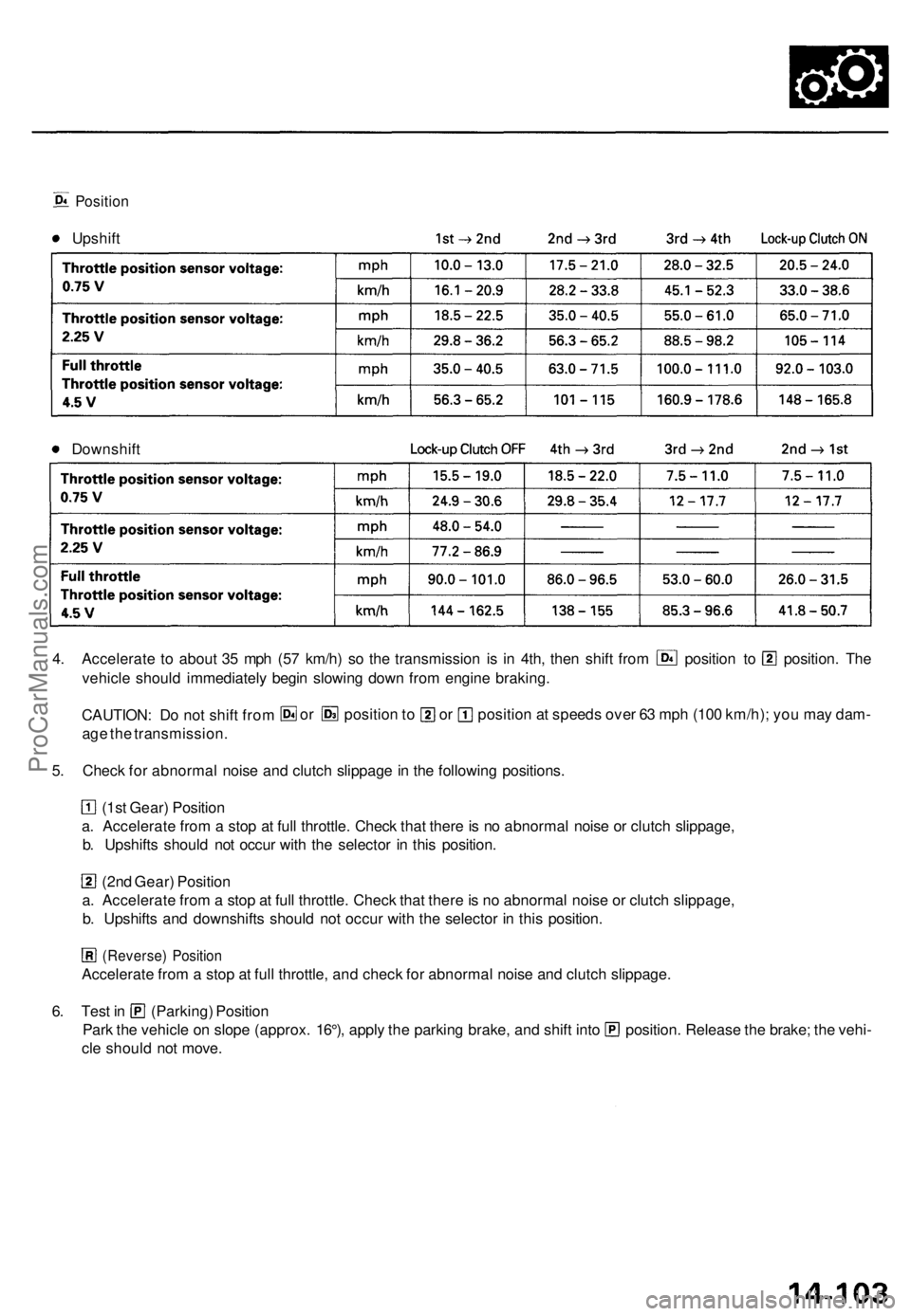
Position
Upshift
Downshift
4. Accelerate to about 35 mph (57 km/h) so the transmission is in 4th, then shift from position to position. The
vehicle should immediately begin slowing down from engine braking.
CAUTION: Do not shift from
age the transmission.
or position to or position at speeds over 63 mph (100 km/h); you may dam-
5. Check for abnormal noise and clutch slippage in the following positions.
(1st Gear) Position
a. Accelerate from a stop at full throttle. Check that there is no abnormal noise or clutch slippage,
b. Upshifts should not occur with the selector in this position.
(2nd Gear) Position
a. Accelerate from a stop at full throttle. Check that there is no abnormal noise or clutch slippage,
b. Upshifts and downshifts should not occur with the selector in this position.
(Reverse) Position
Accelerate from a stop at full throttle, and check for abnormal noise and clutch slippage.
6. Test in (Parking) Position
Park the vehicle on slope (approx. 16°), apply the parking brake, and shift into position. Release the brake; the vehi-
cle should not move.ProCarManuals.com
Page 995 of 1771
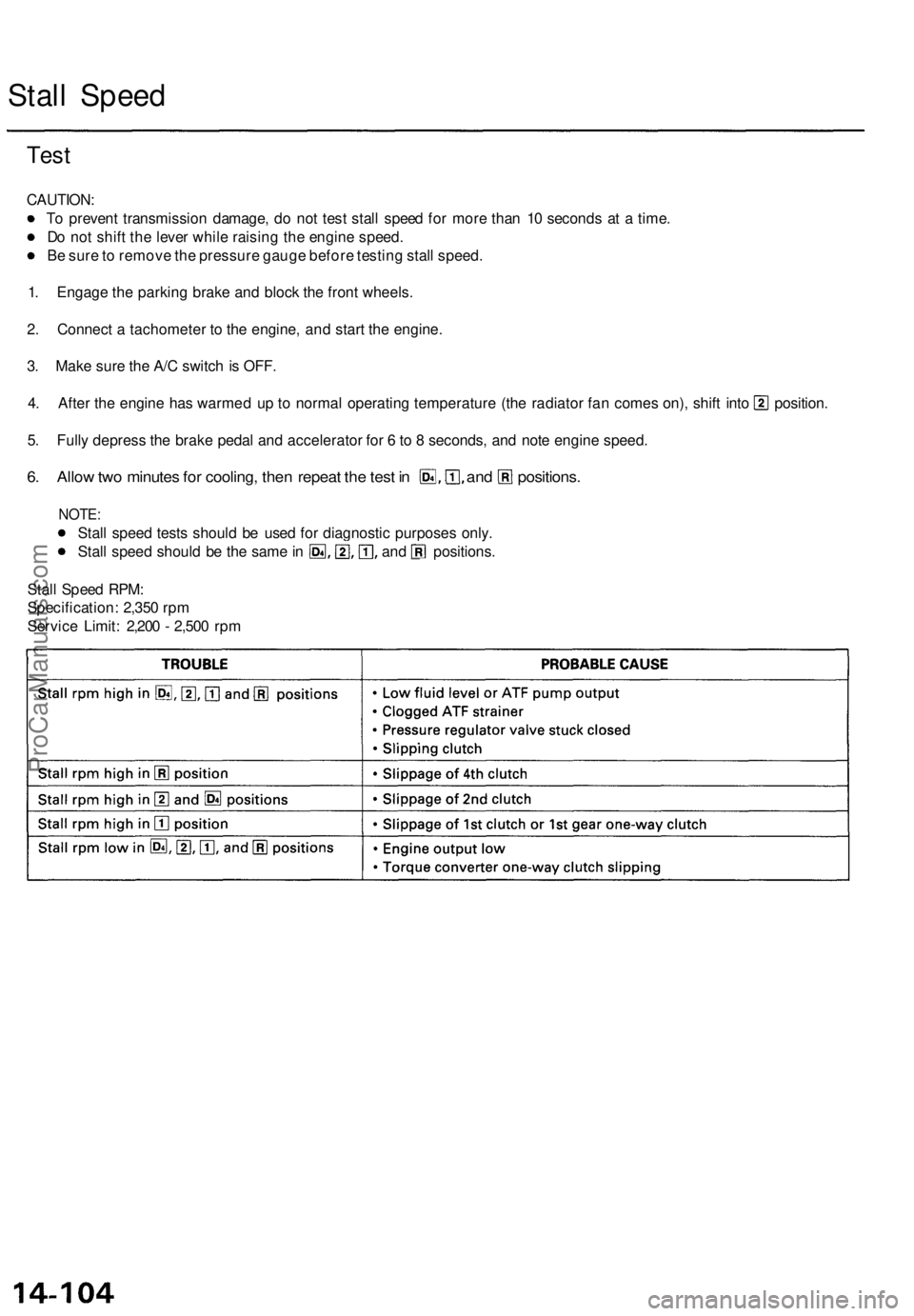
Stall Spee d
Test
CAUTION :
T o preven t transmissio n damage , d o no t tes t stal l spee d fo r mor e tha n 1 0 second s a t a time .
D o no t shif t th e leve r whil e raisin g th e engin e speed .
B e sur e to remov e th e pressur e gaug e befor e testin g stal l speed .
1 . Engag e th e parkin g brak e an d bloc k th e fron t wheels .
2 . Connec t a tachomete r t o th e engine , an d star t th e engine .
3 . Mak e sur e th e A/ C switc h is OFF .
4. Afte r th e engin e ha s warme d u p t o norma l operatin g temperatur e (th e radiato r fa n come s on) , shif t int o position .
5 . Full y depres s th e brak e peda l an d accelerato r fo r 6 to 8 seconds , an d not e engin e speed .
6. Allo w tw o minute s fo r cooling , the n repea t th e tes t i n and positions .
NOTE:
Stall spee d test s shoul d b e use d fo r diagnosti c purpose s only .
Stall spee d shoul d b e th e sam e in an d _ positions .
Stal l Spee d RPM :
Specification : 2,35 0 rp m
Servic e Limit : 2,20 0 - 2,50 0 rp m
ProCarManuals.com
Page 996 of 1771
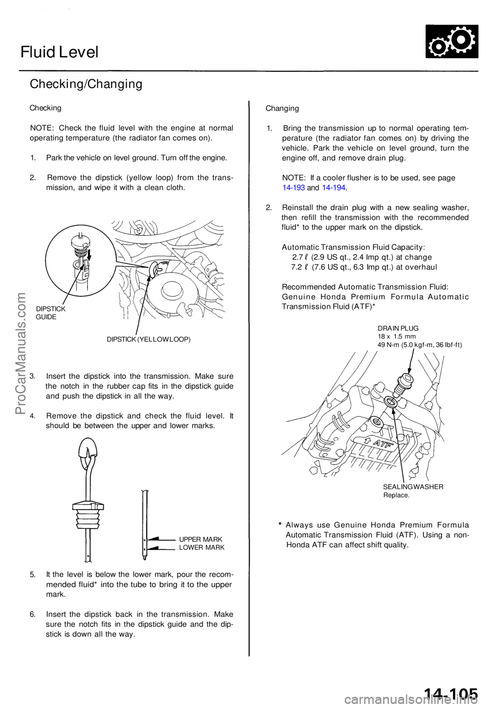
Fluid Leve l
Checking/Changin g
Checking
NOTE : Chec k th e flui d leve l wit h th e engin e a t norma l
operatin g temperatur e (th e radiato r fa n come s on) .
1 . Par k th e vehicl e o n leve l ground . Tur n of f th e engine .
2 . Remov e th e dipstic k (yello w loop ) fro m th e trans -
mission , an d wip e i t wit h a clea n cloth .
DIPSTIC KGUIDE
3.
4 .
DIPSTIC K (YELLO W LOOP )
Insert th e dipstic k int o th e transmission . Mak e sur e
th e notc h i n th e rubbe r ca p fit s i n th e dipstic k guid e
an d pus h th e dipstic k i n al l th e way .
Remov e th e dipstic k an d chec k th e flui d level . I t
shoul d b e betwee n th e uppe r an d lowe r marks .
5.
6 .
UPPE R MAR KLOWE R MAR K
It th e leve l i s belo w th e lowe r mark , pou r th e recom -
mended fluid * int o th e tub e t o brin g i t t o th e uppe r
mark.
Inser t th e dipstic k bac k i n th e transmission . Mak e
sur e th e notc h fit s i n th e dipstic k guid e an d th e dip -
stic k i s dow n al l th e way . Changin
g
1 . Brin g th e transmissio n u p t o norma l operatin g tem -
peratur e (th e radiato r fa n come s on ) b y drivin g th e
vehicle . Par k th e vehicl e o n leve l ground , tur n th e
engin e off , an d remov e drai n plug .
NOTE : I f a coole r flushe r i s t o b e used , se e pag e
14-19 3 an d 14-194 .
2. Reinstal l th e drai n plu g wit h a ne w sealin g washer ,
the n refil l th e transmissio n wit h th e recommende d
fluid * t o th e uppe r mar k o n th e dipstick .
Automati c Transmissio n Flui d Capacity :
2. 7 (2. 9 U S qt. , 2. 4 Im p qt. ) a t chang e
7.2 (7. 6 U S qt. , 6. 3 Im p qt. ) a t overhau l
Recommende d Automati c Transmissio n Fluid :
Genuin e Hond a Premiu m Formul a Automati c
Transmissio n Flui d (ATF) *
DRAIN PLU G18 x 1. 5 m m49 N- m (5. 0 kgf-m , 3 6 Ibf-ft )
SEALIN G WASHE R
Replace .
Always us e Genuin e Hond a Premiu m Formul a
Automati c Transmissio n Flui d (ATF) . Usin g a non -
Hond a AT F ca n affec t shif t quality .
ProCarManuals.com
Page 997 of 1771
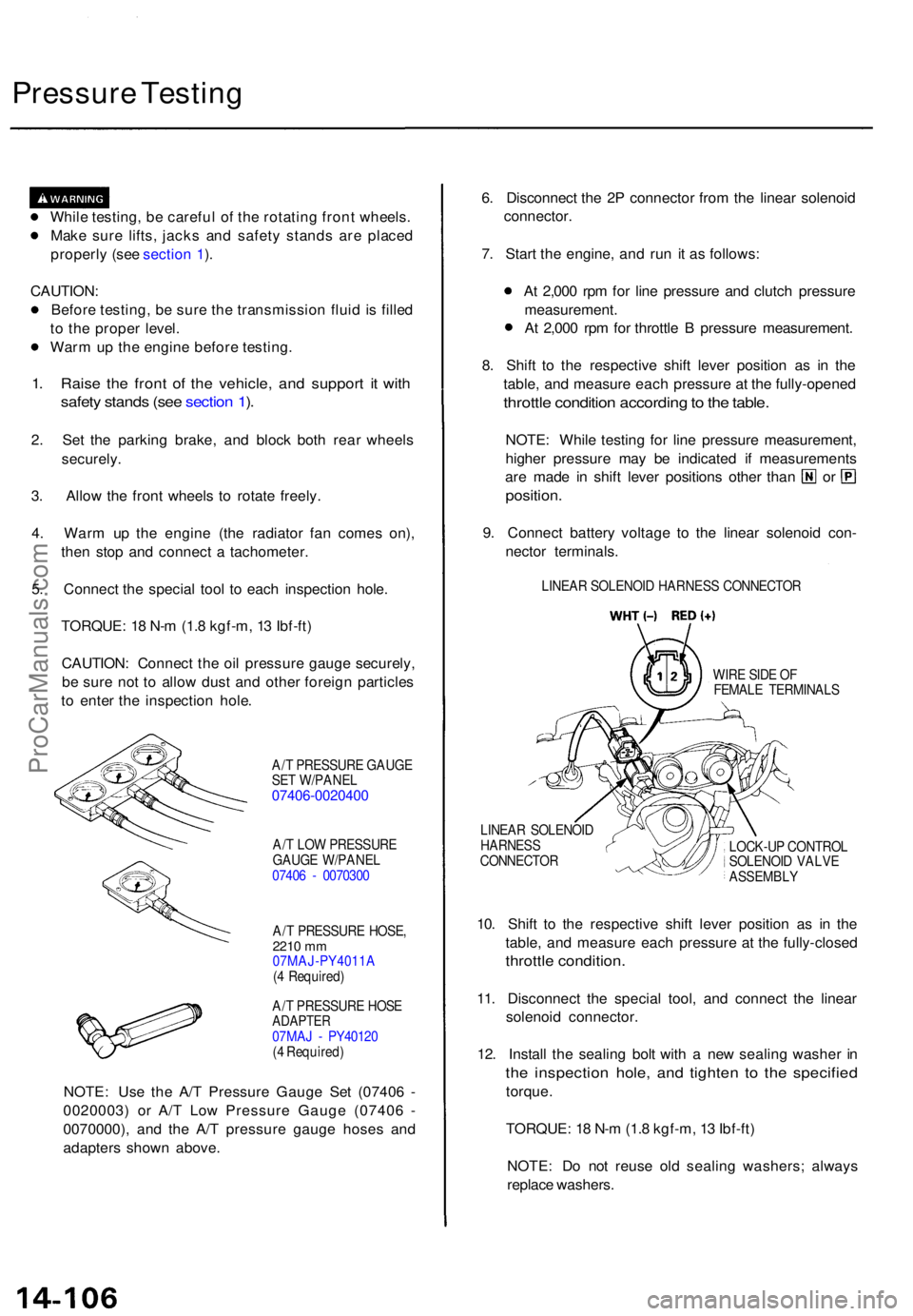
Pressure Testin g
While testing , b e carefu l o f th e rotatin g fron t wheels .
Mak e sur e lifts , jack s an d safet y stand s ar e place d
properl y (se e sectio n 1 ).
CAUTION :
Befor e testing , b e sur e th e transmissio n flui d is fille d
t o th e prope r level .
War m u p th e engin e befor e testing .
1. Rais e th e fron t o f th e vehicle , an d suppor t i t wit h
safet y stand s (se e sectio n 1 ).
2 . Se t th e parkin g brake , an d bloc k bot h rea r wheel s
securely .
3. Allo w th e fron t wheel s t o rotat e freely .
4 . War m u p th e engin e (th e radiato r fa n come s on) ,
the n sto p an d connec t a tachometer .
5 . Connec t th e specia l too l t o eac h inspectio n hole .
TORQUE : 1 8 N- m (1. 8 kgf-m , 1 3 Ibf-ft )
CAUTION : Connec t th e oi l pressur e gaug e securely ,
b e sur e no t t o allo w dus t an d othe r foreig n particle s
t o ente r th e inspectio n hole .
A/T PRESSUR E GAUG E
SE T W/PANE L
07406-002040 0
A/T LO W PRESSUR E
GAUG E W/PANE L
0740 6 - 007030 0
A/ T PRESSUR E HOSE ,
2210 mm07MAJ-PY4011 A
( 4 Required )
A/ T PRESSUR E HOS E
ADAPTE R07MAJ - PY4012 0
( 4 Required )
NOTE: Us e th e A/ T Pressur e Gaug e Se t (0740 6 -
0020003 ) o r A/ T Lo w Pressur e Gaug e (0740 6 -
0070000) , an d th e A/ T pressur e gaug e hose s an d
adapter s show n above . 6
. Disconnec t th e 2 P connecto r fro m th e linea r solenoi d
connector .
7 . Star t th e engine , an d ru n i t a s follows :
A t 2,00 0 rp m fo r lin e pressur e an d clutc h pressur e
measurement .
A t 2,00 0 rp m fo r throttl e B pressur e measurement .
8 . Shif t t o th e respectiv e shif t leve r positio n a s i n th e
table , an d measur e eac h pressur e a t th e fully-opene d
throttle conditio n accordin g to th e table .
NOTE : Whil e testin g fo r lin e pressur e measurement ,
highe r pressur e ma y b e indicate d i f measurement s
are mad e i n shif t leve r position s othe r tha n o r
position .
9. Connec t batter y voltag e t o th e linea r solenoi d con -
necto r terminals .
LINEAR SOLENOI D HARNES S CONNECTO R
WIR E SID E O F
FEMAL E TERMINAL S
LINEA R SOLENOI D
HARNES S
CONNECTO R LOCK-U
P CONTRO L
SOLENOI D VALV E
ASSEMBL Y
10. Shif t t o th e respectiv e shif t leve r positio n a s i n th e
table , an d measur e eac h pressur e a t th e fully-close d
throttle condition .
11. Disconnec t th e specia l tool , an d connec t th e linea r
solenoi d connector .
12 . Instal l th e sealin g bol t wit h a ne w sealin g washe r i n
th e inspectio n hole , an d tighte n t o th e specifie d
torque.
TORQUE : 1 8 N- m (1. 8 kgf-m , 1 3 Ibf-ft )
NOTE : D o no t reus e ol d sealin g washers ; alway s
replac e washers .
ProCarManuals.com
Page 1006 of 1771
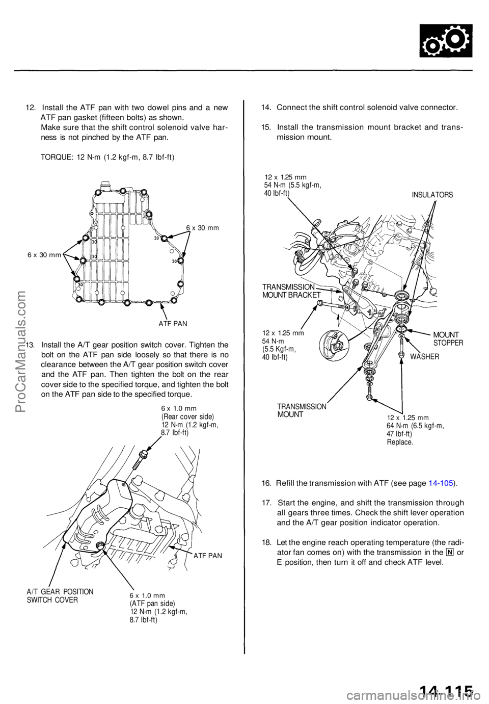
12. Instal l th e AT F pa n wit h tw o dowe l pin s an d a ne w
AT F pa n gaske t (fiftee n bolts ) a s shown .
Mak e sur e tha t th e shif t contro l solenoi d valv e har -
nes s i s no t pinche d b y th e AT F pan .
TORQUE : 1 2 N- m (1. 2 kgf-m , 8. 7 Ibf-ft )
6 x 3 0 m m
6 x 30 m m
13.
AT F PA N
Instal l th e A/ T gea r positio n switc h cover . Tighte n th e
bol t o n th e AT F pa n sid e loosel y s o tha t ther e i s n o
clearanc e betwee n th e A/ T gea r positio n switc h cove r
an d th e AT F pan . The n tighte n th e bol t o n th e rea r
cove r sid e to th e specifie d torque , an d tighte n th e bol t
o n th e AT F pa n sid e to th e specifie d torque .
6 x 1. 0 m m(Rea r cove r side )
1 2 N- m (1. 2 kgf-m ,
8. 7 Ibf-ft )
ATF PA N
A/T GEA R POSITIO N
SWITC H COVE R6 x 1. 0 m m(AT F pa n side )
1 2 N- m (1.2 kgf-m ,
8. 7 Ibf-ft )
14. Connec t th e shif t contro l solenoi d valv e connector .
15 . Instal l th e transmissio n moun t bracke t an d trans -
mission mount .
12 x 1.2 5 mm54 N- m (5. 5 kgf-m ,
4 0 Ibf-ft )
INSULATORS
TRANSMISSIO NMOUNT BRACKE T
12 x 1.2 5 mm54 N- m(5.5 Kgf-m ,
4 0 Ibf-ft )
MOUN TSTOPPE R
WASHER
TRANSMISSIO NMOUNT12 x 1.2 5 mm64 N- m (6. 5 kgf-m ,
4 7 Ibf-ft )
Replace .
16. Refil l th e transmissio n wit h AT F (se e pag e 14-105 ).
17 . Star t th e engine , an d shif t th e transmissio n throug h
al l gear s thre e times . Chec k th e shif t leve r operatio n
an d th e A/ T gea r positio n indicato r operation .
18 . Le t th e engin e reac h operatin g temperatur e (th e radi -
ator fa n come s on ) wit h th e transmissio n in th e o r
E position , the n tur n i t of f an d chec k AT F level .
ProCarManuals.com