Page 435 of 1771

Differential Assembl y
Removal
• Mak e sur e jack s an d safet y stand s ar e place d properly ,
an d hois t bracket s ar e attache d to correc t position s o n
th e engine .
• Appl y parkin g brak e an d bloc k rea r wheel s s o th e
vehicl e wil l no t rol l of f stand s an d fal l o n yo u whil e
workin g unde r it .
CAUTION : Us e fende r cover s t o avoi d damagin g painte d
surfaces .
1. Remov e th e drai n plug , an d drai n th e differentia l oi l
(se e pag e 15-4 ).
2 . Remov e th e driveshaft s an d intermediat e shaf t (se e
sectio n 16 ).
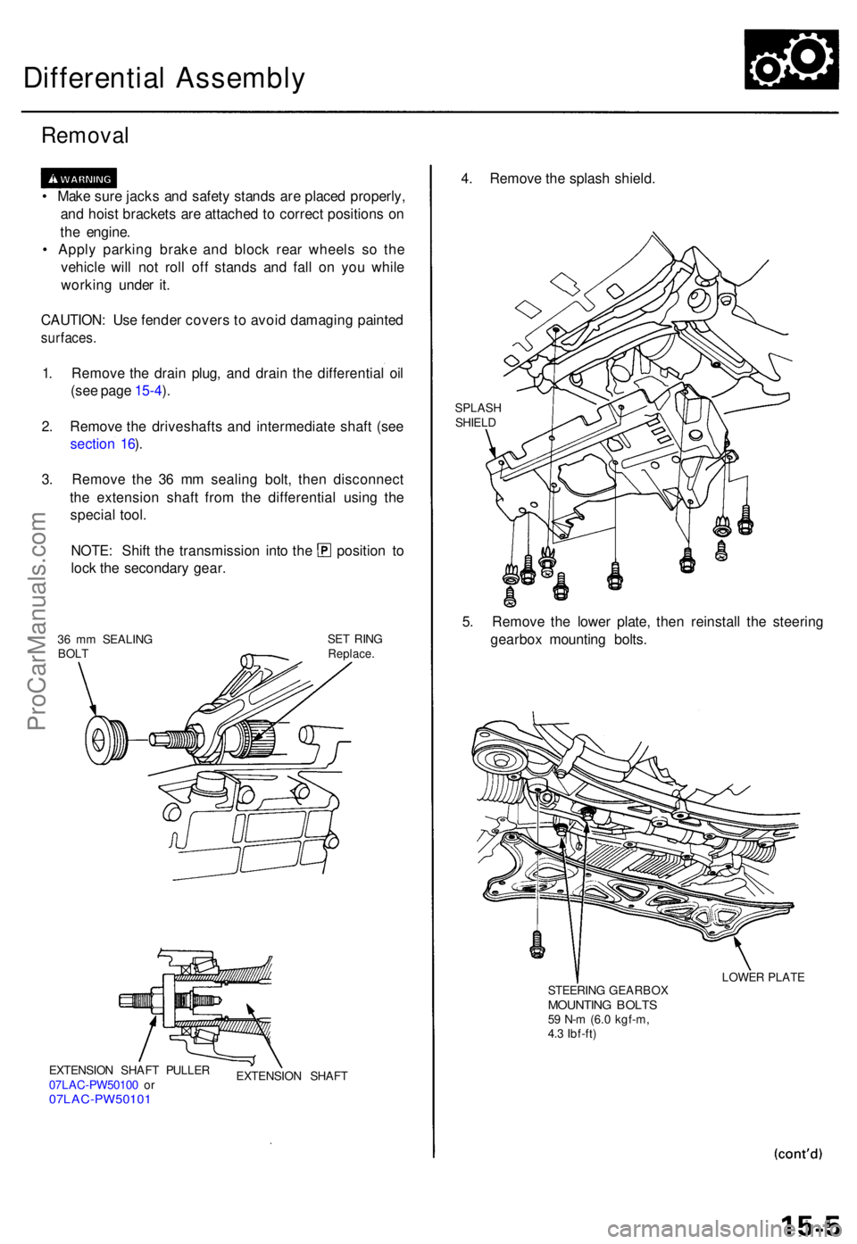
3 . Remov e th e 3 6 m m sealin g bolt , the n disconnec t
th e extensio n shaf t fro m th e differentia l usin g th e
specia l tool .
NOTE : Shif t th e transmissio n int o th e positio n t o
loc k th e secondar y gear .
36 m m SEALIN G
BOL T SE
T RIN GReplace .
EXTENSIO N SHAF T PULLE R
07LA C-PW5010 0 o r
07LAC-PW5010 1
EXTENSION SHAF T
4. Remov e th e splas h shield .
SPLAS H
SHIEL D
5. Remov e th e lowe r plate , the n reinstal l th e steerin g
gearbo x mountin g bolts .
STEERIN G GEARBO XMOUNTING BOLT S59 N- m (6. 0 kgf-m ,
4. 3 Ibf-ft ) LOWE
R PLAT E
ProCarManuals.com
Page 455 of 1771
Differential Assembly
Installation
NOTE: If the differential case is replaced, the 26 mm
shim must be adjusted.
a. Install the differential assembly.
b. Measure the clearance between the differential case
and the torque converter housing.
26 mm SHIM
c. Select the 26 mm shim from the following table.
26 mm SHIM
1. Install the two dowel pins on the differential assem-
bly.
DOWEL PINS
2. Attach the differential assembly to the engine, then
tighten the two mounting bolts (marked with in
this figure) loosely.
3. Install the 26 mm shim, then tighten the mounting
bolts to the specified torque.
12 x
1.25
mm
64 N-m (6.5 kgf-m,
47 Ibf-ft)
26 mm SHIMProCarManuals.com
Page 488 of 1771

Steering Gearbo x
Installatio n (cont'd )
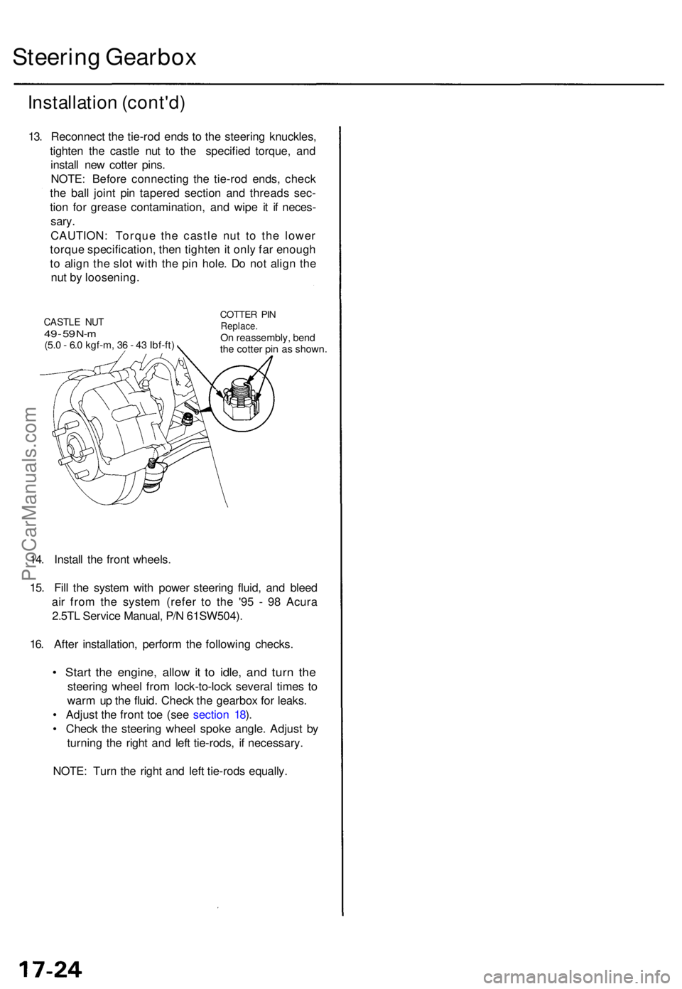
13. Reconnec t th e tie-ro d end s t o th e steerin g knuckles ,
tighte n th e castl e nu t t o th e specifie d torque , an d
instal l ne w cotte r pins .
NOTE : Befor e connectin g th e tie-ro d ends , chec k
th e bal l join t pi n tapere d sectio n an d thread s sec -
tio n fo r greas e contamination , an d wip e i t i f neces -
sary.
CAUTION : Torqu e th e castl e nu t t o th e lowe r
torqu e specification , the n tighte n it onl y fa r enoug h
t o alig n th e slo t wit h th e pi n hole . D o no t alig n th e
nu t b y loosening .
14 . Instal l th e fron t wheels .
15 . Fil l th e syste m wit h powe r steerin g fluid , an d blee d
ai r fro m th e syste m (refe r t o th e '9 5 - 9 8 Acur a
2.5T L Servic e Manual , P/ N 61SW504) .
16 . Afte r installation , perfor m th e followin g checks .
• Star t th e engine , allo w it t o idle , an d tur n th e
steerin g whee l fro m lock-to-loc k severa l time s t o
war m u p th e fluid . Chec k th e gearbo x fo r leaks .
• Adjus t th e fron t to e (se e sectio n 18 ).
• Chec k th e steerin g whee l spok e angle . Adjus t b y
turning the righ t an d lef t tie-rods , i f necessary .
NOTE : Tur n th e righ t an d lef t tie-rod s equally .
CASTLE NU T49 - 5 9 N- m(5. 0 - 6. 0 kgf-m , 3 6 - 4 3 Ibf-ft )
COTTE R PI NReplace .On reassembly , ben d
th e cotte r pi n a s shown .
ProCarManuals.com
Page 495 of 1771

Front Suspensio n
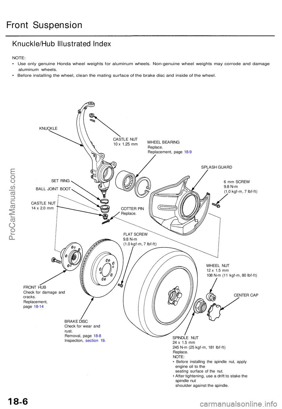
Knuckle/Hu b Illustrated Index
NOTE :
• Us e onl y genuin e Hond a whee l weight s fo r aluminu m wheels . Non-genuin e whee l weight s ma y corrod e an d damag e
aluminu m wheels .
• Befor e installin g th e wheel , clea n th e matin g surfac e o f th e brak e dis c an d insid e o f th e wheel .
KNUCKL E
SET RIN G
BAL L JOIN T BOO T
CASTL E NU T
14 x 2. 0 m m
FRON T HU B
Chec k fo r damag e an d
cracks .Replacement ,
pag e 18-1 4 WHEE
L BEARIN G
Replace.Replacement , pag e 18- 9
SPLAS H GUAR D
6 m m SCRE W
9.8 N- m(1.0 kgf-m , 7 Ibf-ft )
WHEE L NU T
12 x 1. 5 m m108 N- m (1 1 kgf-m , 8 0 Ibf-ft )
CENTE R CA P
BRAK E DIS C
Chec k fo r wea r an d
rust .Removal , pag e 18- 8
Inspection , sectio n 1 9 SPINDL
E NU T
24 x 1. 5 m m245 N- m (2 5 kgf-m , 18 1 Ibf-ft )
Replace .
NOTE :
• Befor e installin g th e spindl e nut , appl y
engine oi l t o th eseatin g surfac e o f th e nut .• Afte r tightening , us e a drif t t o stak e th espindl e nu tshoulde r agains t th e spindle .
CASTLE NU T10 x 1.2 5 mm
COTTE R PI N
Replace .
FLAT SCRE W9.8 N- m(1.0 kgf-m , 7 Ibf-ft )
ProCarManuals.com
Page 508 of 1771

Troubleshooting Precautions
ABS Indicator Light:
The ABS indicator light comes on for three seconds and then goes off when the control unit detects no problem during the
initial diagnosis right after the engine starts. However, the ABS indicator light can stay on for up to 40 seconds when the
control unit starts to check for pump overrun, etc. during the initial diagnosis. The ABS indicator light comes on, and the
ABS control unit memorizes the diagnostic trouble code (DTC) under certain conditions.
• The parking brake is applied for more than 30 seconds while the vehicle is being driven. (DTC 2-1)
• The transmission downshifted excessively. (DTC 4-1, 4-2)
• The vehicle loses traction, and the front wheels spin for more than one minute when starting from a stuck condition on
a muddy, snowy, or sandy road. (DTC 4-8)
• Tire adhesion is lost due to excessive cornering speed. (DTC 5, 5-4, 5-8)
• The vehicle is driven on an extremely rough road. (DTC 8-1)
• The vehicle is interfered by strong radio waves (noise), for example, illegal radio, etc. (DTC 8-2)
NOTE: If there is any trouble in the system, the ABS indicator light comes on during driving.
Diagnostic Trouble Code (DTC):
• When the control unit detects a problem and the ABS indicator light comes on, the control unit memorizes the DTC.
• The control unit has three memory registers. When a problem occurs, the control unit stores the DTC in the first memory
register. If another problem occurs, or the same problem occurs again, the control unit moves the first DTC to the next
memory register, and stores the second DTC in the first register. If there's a third problem occurrence, the two existing
DTCs are moved up one register, and the third DTC is stored in the first register. If problems continue to occur, the oldest
problem is moved out of the last register and lost, and the most recent problem is stored in the first register. When the
same problem occurs three times, the same DTC is stored in all memory registers. (Refer to the Symptom-to-System
Chart for diagnostic period.)
• The most recent DTC is indicated first, and the oldest DTC is indicated last.
• The DTCs are erased from the control unit when the ABS control unit +B2 power supply or connector is disconnected.
• The control unit's memory can be erased by disconnecting the ABS B2 fuse for more than three seconds.
Self-diagnosis:
• There are three self-diagnosises described below.
Initial diagnosis: Performed right after the engine starts until the ABS indicator light goes off.
Regular diagnosis: Continuously performed (under some conditions) after the ABS indicator light goes off until the
engine stops.
Individual part/system diagnosis: Diagnosis about a specific part/system under its operating conditions.
• The CPU (central processing unit) controls the following when it detects a problem during self-diagnosis:
Turns the ABS indicator light ON.
Turns the front and rear fail-safe relays off.
Stops the ABS control.
Stops the ABS pump. (The pump may work under some conditions.)
After the DTC is stored in the control unit, the CPU stops self-diagnosis.ProCarManuals.com
Page 509 of 1771

Kickback and Pump Operation:
• When the engine is started, the ABS control unit begins the initial diagnosis and operates the solenoid valve one time.
The kickback may be felt when the brake pedal is depressed.
• When the ABS control unit detects the pressure switch OFF signal during the initial diagnosis, it operates the pump
motor, and performs the pump motor over-run diagnosis and pump motor diagnosis. Therefore, there are two cases
where the pump motor operates or does not operate after the engine is started.
• Normally, after the initial diagnosis, the pump motor operates based on the pressure switch signal, regardless of the
vehicle speed.
Troubleshooting:
• When two or three DTCs are stored in the control unit, perform troubleshooting for the DTC that appears first.
• When a customer's reported problem cannot be verified on the car, ask the customer about the conditions when the
ABS indicator light came ON, and test-drive the car under those conditions, if possible. When the ABS indicator light
does not come ON during the test, check for loose terminals and check by shaking the harnesses and connectors while
following the flowchart.
• The connector terminal numbers are viewed from the wire side for the female terminals, and from the terminal side for
the male terminals.
• After the repair is completed, test-drive the car and check that the ABS indicator light does not come ON again during
the test. (Refer to the Symptom-to-System Chart for diagnostic period.)ProCarManuals.com
Page 510 of 1771
Diagnostic Troubl e Cod e (DTC ) Indicatio n
1. Connec t th e SC S servic e connecto r t o th e servic e chec k connecto r unde r th e glov e box .
SCS SERVIC E CONNECTO R07PAZ-001010 0
SERVICE CHEC KCONNECTO R (2P )
2. Tur n th e ignitio n switc h O N (II) , bu t d o no t star t th e engine .
3 . Recor d th e blinkin g frequenc y o f th e AB S indicato r light . Th e blinkin g frequenc y indicate s th e diagnosti c troubl e cod e
(DTC) .
NOTE: Chec k th e DT C carefull y an d recor d it . Th e memor y o f th e DT C is erase d if th e connecto r i s disconnecte d fro m
the AB S contro l unit .
GAUG E ASSEMBL Y
ABS INDICATO R LIGH T
ProCarManuals.com
Page 511 of 1771
DTC Indication Pattern (When the ABS control unit detected a problem three times.):
Turn the ignition
switch ON (II)
ABS
Indicator
light on
ABS
Indicator
light off
DTC:
4-2
Main Coda: 4
Sub-Code: 2
Connect the
SCS service
connector
2 Second Second
pause pause
5 Second
pause
1
Second
pause
5 Second
pause
1
Second
pause
2 Seconds
• Turn the ignition switch ON (II). The ABS indicator light comes on for two seconds to check the bulb.
• The ABS control unit indicates the DTC three times.
• If you miscount the blinking frequency or if you recheck the blinking frequency, turn the ignition switch OFF then
turn it ON (II) to cycle the ABS indicator light again.
4. Remove the SCS service connector.
NOTE: The Malfunction Indicator Lamp (MIL) will stay on after the engine is started if the SCS service connector is
connected.
5. Remove the ABS B2 (15 A) fuse in the under-hood fuse/relay box for at least three seconds to erase the ABS control
unit's memory.ProCarManuals.com